|
|
| Search | Car Forums | Gallery | Articles | Helper | Air Dried Fresh Beef Dog Food | IgorSushko.com | Corporate |
|
|||||||
| WIP - Street Post topics for any "Works In Progress" street vehicles projects in this sub-forum. |
 |
 Show Printable Version | Show Printable Version |  Subscribe to this Thread
|
|
|
Thread Tools |
|
#1
 10-28-2006, 07:29 PM
|
||||
|
||||
|
1999 Mustang Cobra--extreme detail!
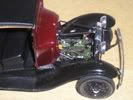
Here's another of my rebuild projects. My modeling skills just weren't "up there" when I was 10, 11, 12, etc. This car was good-looking, so I felt compelled to resurrect it. It's Revell's 1999 Mustang Cobra SVT. Little did I know what I was getting into...
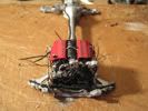
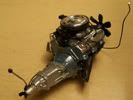
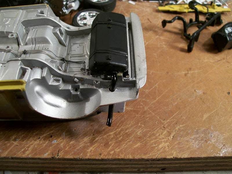
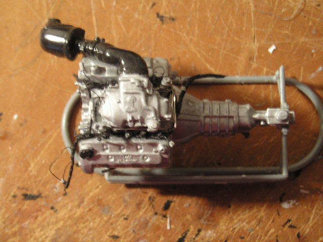 Here's the engine (not done yet). I discovered that Revell mix-matched parts for the old and new Mustang Cobras. When the body style changed in 1999, so did the engine. Revell only made half the changes The upper intake pictured here is accurate, but I had to get another Cobra (parts kit only) from E-bay to get it. Revell included both the old and new style intake systems, then directed to use the new lower and old upper intake in the directions. These parts don't even fit together, but I didn't know at the young age when I built this kit. So, I finally got the correct part. Revell did say to use the correct valve covers (while including both styles). The biggest problem was the front cover; it included the brackets to hold on the Distributorless Ignition Modules, which the newer Cobra doesn't have (it uses coil-over-plug ignition). I had to cut the brackets off. You can see my complex wiring harness here. It is made of loops of .13mm wire and a bunch of masking tape. See http://www.automotiveforums.com/vbul...d.php?t=631380 for my general method of making wiring harnesses. In this picture, you can also see my fuel rail, pressure regulator, and transducer (that is the black unit at the lower left part of the rail. I still need to add the vacuum harness, EGR pipe, EVR, throttle cable bracket, throttle linkage, CCV hose, oil cap and valve cover decals, and of course the belts and pulleys. 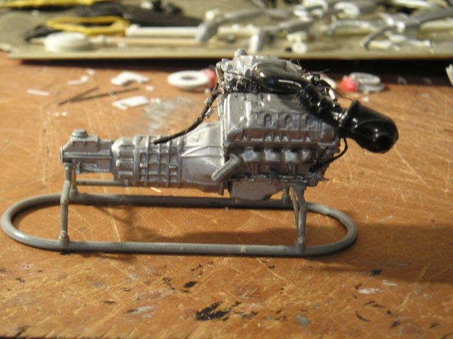 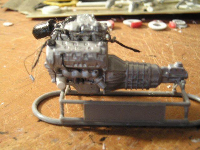 It's hard to see, but behind the oil filter is the oil cooler. The kit part was the one used on cars with automatic transmissions. This car has a manual, so I had to rebuild the unit to be more accurate. You can also see the large hole in the exhaust manifold for the EGR pipe. 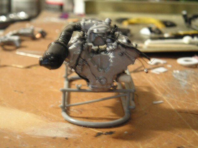 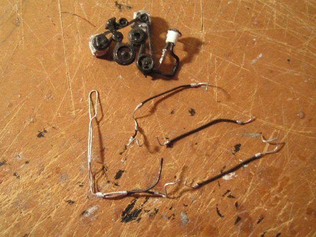 The 4.6L V8 used in this car doesn't develop enough vacuum to operate power brakes. So, Ford uses "Hydroboost," which uses power steering fluid to operate the power brakes. Here are the resulting complex power steering hoses. The very large one includes the fluid cooler, which runs along the front of the radiator. You can also see the belts and pulleys, with the other hoses and the tank attached. 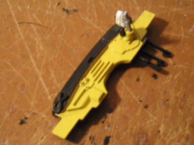 Here is the firewall, painted and ready to go. The slot on the left will soon be filled with a part that includes the A/C accumulator and the main connector for the PCM harness. Revell called this part the "wiper motor," a component which is actually located under the cowl on the driver's side. The two fittings are for the heater hoses. 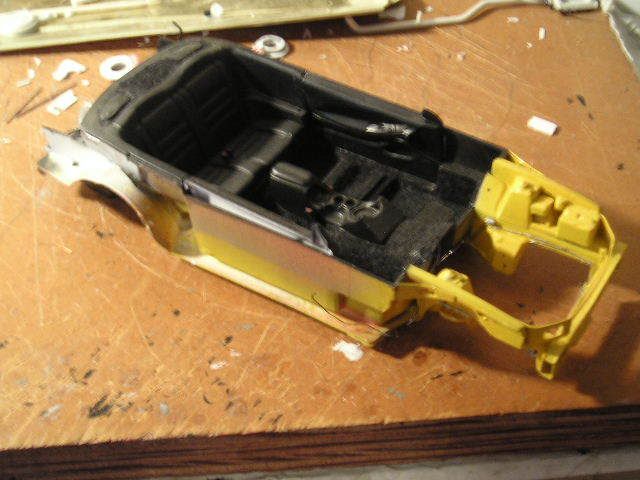 Here is the combined chassis and interior tub. I'm planning to assemble this like a real car--everything will be attached to either the engine or the chassis, and when I drop in the engine, I'll hook it all up. If you look closely at the passenger side, you'll see a small black wire. This is actually the line going from the fuel tank to the evaporative emissions canister. I haven't yet installed that part. You may also see bits of red on either side of the console; those are the seatbelt buckles (the "push" buttons). 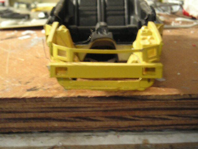 Most of what you see here is scratch-built. The model had inadequate sheet metal details; I added the bumper brace, headlight surrounds, splash pan, and braces on the outside (connecting to the front of the interior area). Those two silver lines inside the engine bay are the fuel lines. I also had to remove the large block-like units where the engine was supposed to mount. They were simply inaccurate, and interfered with the steering box. 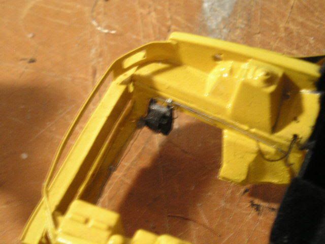 Here is the ABS hydraulic unit. It took 16 pieces of plastic, but was worth it; it looks great. You can clearly see the former locations of those engine mount "blocks" in this picture; they are now angled and will integrate into the front suspension cradle when I install it. 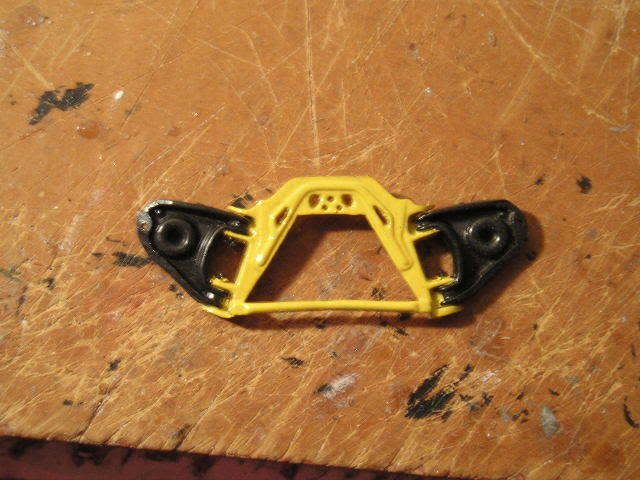 Here's the cradle. I know the yellow is way overdone--I'll tone it down with a wash and a spray of "mud" later. I used a drill and knife to cut out those holes; they were solid in the kit part.  Here's the chassis. I used silver enamel for the metal, then toned it down with Dull Cote. This model is my first time ever using "unit" technology; I prebent all the fuel lines, then connected them with clips. Then, I attached them to the fuel tank. I finally dropped the whole fuel system in as a unit, not piece by piece. The fuel tank was attached to the chassis on the kit part, but...  ...I removed it with a saw, built a top, then reattached it more accurately. I still need to finish the straps at the rear, attaching them to the chassis (for looks only; they won't help hold it). You can see my fuel filter here as well. If you look closely, you'll also see my brake hard lines and the valves that will later connect them with the flexible brake hoses to the calipers. Oops--I forgot to paint the valve. It'll be silver. 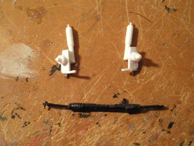 Here are my handbuilt steering parts. Only the shocks and wheel hubs are from the kit (the hubs were cut from the original kit suspension). The spindles are handbuilt, and set up to lower the car a couple scale inches. The steering rack is totally scratch-built, and actually works; The center part (the rubber coating off of an electrical wire) and the boots (coils of copper wire) will stay fixed and attached to the frame, while the tie rod ends (a paper clip, with the ends ground down and bent into loops) will move back and forth. It's stiff, but sufficient for posing the suspension. The steering box is part of an old tie rod from a 1/20 scale Camaro I long ago junked. It will have those complicated power steering hoses attached to it, along with the steering shaft. 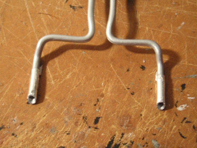 Here is the rear of the exhaust system. I drilled out the tips, wrapped them with Bare-Metal chrome foil, and painted them black inside. The rest of the exhaust is Testors Metalizer aluminum. 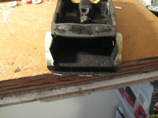 Here is the trunk, with flocking and hand-built side panels. I opened the trunk lid on the body--that was a nightmare. I'll show that when I finish polishing the paint on the body. You can barely see my paper-clip hinges; the one on the left is up, and the one on the right is down. 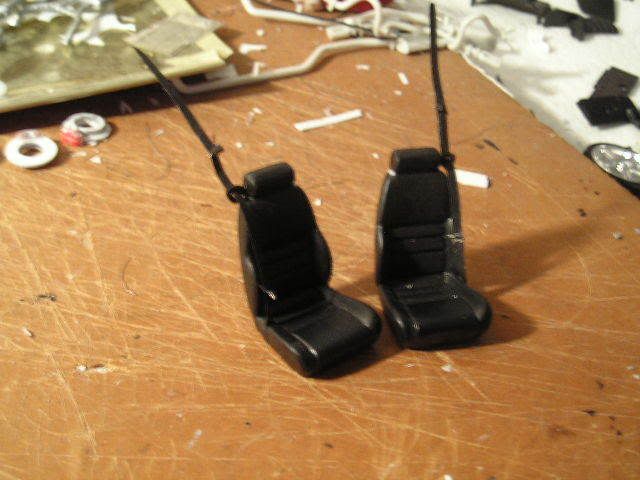 Here are the seats. I added masking tape seatbelts, sheet plastic buckles, and sheet plastic and wire hangers. I also puttied the seam between the kit parts before painting. 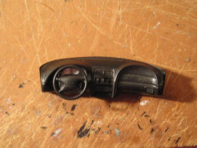 My final installation for the day--the dash. I applied the decal with Micro Set and Micro Sol; it conformed nicely. I still need to add the headlight switch and modify the steering column tilt lever (which is way too big). For the first time in history, my dad finally got a modern Mustang into his auto repair shop, so I'll be taking some pictures for reference. It is a 3.8L V6 car, but has the same interior (except cloth), same wiring (for the most part), brake lines, etc. Next up will be pictures of the polished body! (If you didn't guess already, it's bright yellow). Alex
__________________

|
|
#2
10-28-2006, 08:22 PM
|
|||
|
|||
|
Re: 1999 Mustang Cobra--extreme detail!
Wow nice start on the rework. is it still going to be yellow?
|
|
#3
10-28-2006, 09:39 PM
|
||||
|
||||
|
Re: 1999 Mustang Cobra--extreme detail!
Extreme detail?? Looks challenging. Will the doors open??
I guess this one will look very clean after finished! Good luck!
__________________
 "Oh noez,it has more stickers than me! And a wing too!  
|
|
#4
10-29-2006, 06:15 PM
|
||||
|
||||
|
Re: 1999 Mustang Cobra--extreme detail!
Quote:
Quote:
__________________
|
|
#5
10-30-2006, 11:18 AM
|
|||
|
|||
|
Re: 1999 Mustang Cobra--extreme detail!
the wiring and extreme attention to detail floor me!! I love this car. I can't wait to see it finished!!
__________________
There is a very fine line between "hobby" and "mental illness." 
|
|
#6
10-30-2006, 03:33 PM
|
||||
|
||||
|
Re: 1999 Mustang Cobra--extreme detail!
definatly a nice project youve got goin there, and a great start!.
__________________
On the workbench: Slammed Ram D-50 Caddy STS-V VIP style Two Custom FD3S' With engines Slammed Silverado ...and about 20 others 
|
|
#7
10-31-2006, 01:18 PM
|
||||
|
||||
|
Re: 1999 Mustang Cobra--extreme detail!
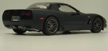
You the guy dong the Corvette for your sis too?
You have a lot of great detail there but you should find a way to get better pics so we can really enjoy the detail!!!
|
|
#8
10-31-2006, 03:00 PM
|
||||
|
||||
|
Re: 1999 Mustang Cobra--extreme detail!
Quote:
My camera's Macro mode doesn't work all too well. It's an Olympus--any tips for getting better shots? I would also appreciate being able to do that.
__________________
|
|
#9
06-18-2007, 06:52 PM
|
||||
|
||||
|
Re: 1999 Mustang Cobra--extreme detail!
Well, with the arrival of summer and my graduation from high school, I'm using the time available to me (which, between two part time jobs and getting ready for college, isn't much) to work on the 'Stang again while the wretched Testors paint strips from my Firebird. I got a new camera for Christmas (those of you who have seen my newer threads, esp. the Firebird, probably noticed), so viewing this model should be a little easier. Blurry pictures hurt my eyes, I'm sure yours too.
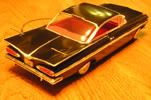
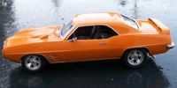
First up is the driver's side engine bay wiring harness. That's right, not only is there an engine harness and an engine bay harness, there are actually two engine bay harnesses. Using various reference shots, I was able to build a pretty accurate unit. Several people requested a tutorial of my wiring technique after seeing it on my Corvette Z06. I'm afraid this harness is much too complex for that, but the general idea is here; in addition, I've refined the technique down to the point where it's quite easy and actually fun (rather than a dreaded experience like my previous method). I call it the "all-wire wiring harness", and you'll see why in a bit. Here goes. First the diagram. This is always my first step, and is one of three diagrams I draw. It shows the layout of the harness and all the components that are connected. I use abbreviations, obviously. It's just a rough sketch, and this actually shows the driver's and passenger's side harnesses connected (I didn't realize they were separate until a little later. It's pretty much the same, though; just a separation and they're two harnesses). 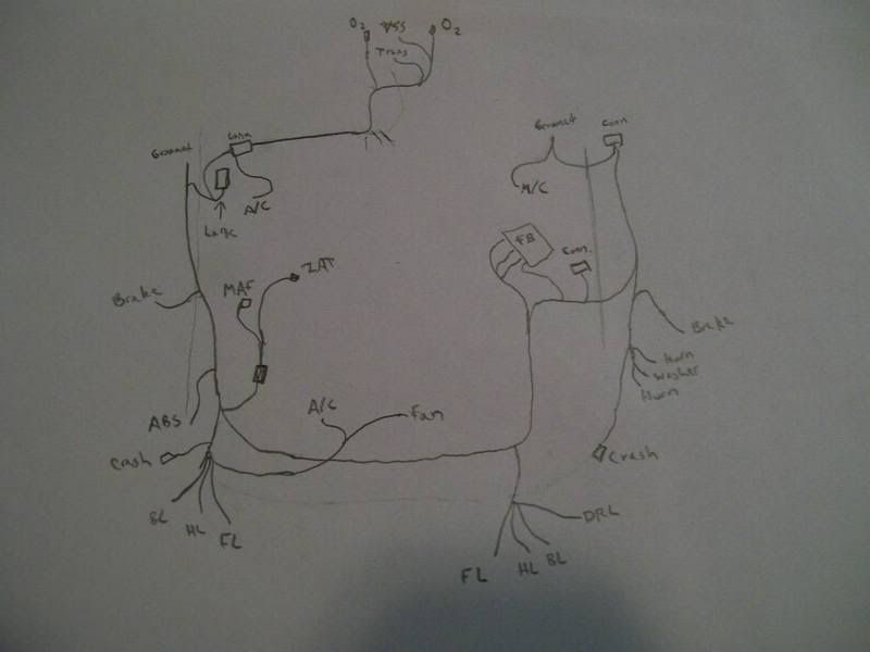 Next diagram: the looping chart. In my latest harness design (the one I'm showing you), there are fewer loops than before because I can easily insert wire stubs. That probably sounds like foreign nonsense to you, but I'll discuss it in a bit. This chart shows each wire that will be in the harness. I've numbered them, so I know how many wires to cut, and I've listed their starting and ending points. These wires form the core of the harness, and most of them also double as the visible wire ends that are attached to parts in the engine bay. I'll need 11 wires to form the core; the wires with arrows on the end will be stubs, and don't loop. Previously, when I used tape for my harnesses, stubs were a pain and I avoided them. But with my current method, they are no problem. 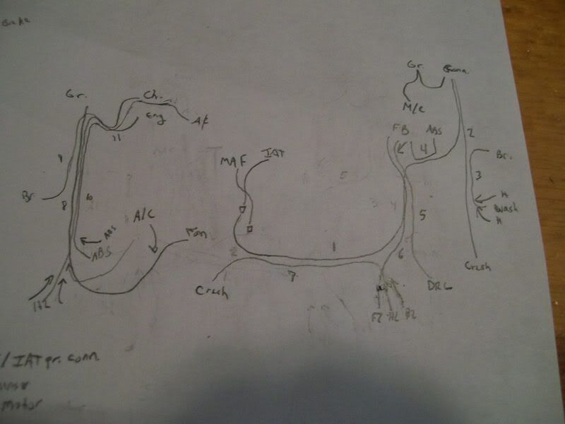 Next, my final diagram: the 1:1 size chart. This shows exactly how big each part of the harness needs to be. When I'm cutting core wires and harness tubing, I lay them directly on this chart so that I cut them to the right length. 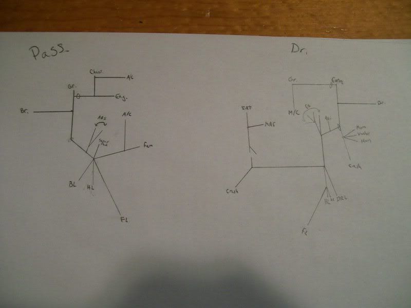 Using charts 2 and 3, I cut the 11 core wires to the proper length. There are only seven in this harness; the 11 number is for the whole engine bay (both sides). Next, I begin making my harness tubing. This replicates the convulted tubing used on modern cars; for old muscle cars with taped harnesses, I use a thin strip of masking tape and wrap it directly around my core wires. In this method, I wrap .13mm wire (the same size I use for core wires) around a large piece of wire that is only used for making the tube. It's not part of the harness. The wire I'm wrapping around is .62mm; I use .44, .41, and .26 for my other sizes of tubing. 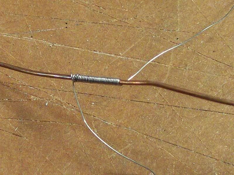 This was all the tubing I could make from one strand of .13mm wire (it came from the mesh shielding inside a co-ax cable). The cable was a left-over from when we wired my house and shop, so it's pretty short, and the tube is not very long. However, this is absolutely not a problem. Another section of tubing can butt up against this one as I build the harness and you can't even see the joint. 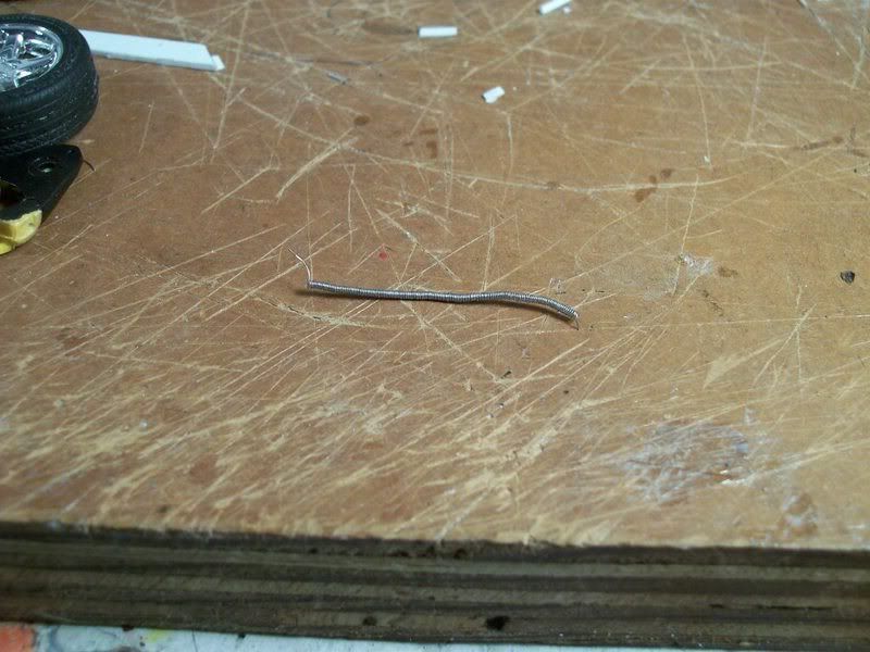 Here you can see my first core wire, with a short length of that .62mm tubing superglued on. Keep in mind that when drawing my diagrams, I never exceed four core wires per .62mm tube, becuase if you do the math, you can't fit any more in there. Never mind the principles of pi r squared, I just use linear measurements (wire diameters) because in this small scale, a tiny bend in the wire will nullify all those complex calculations. Four is all you can get in a .62mm tube (for core wires), period. You can probably get more stubs in just by cramming them in the very end and supergluing them fast, but try threading more than four core wires through and you'll find it can't be done. Of course, I look at the real wiring harness (or picture) to see how big it is in each section; .62mm is quite large, the size used in modern cars. Branches of this harness and all the harness parts in older cars are smaller, and thus use sizes like .44mm, which of course holds fewer core wires. All this must be considered when making my diagrams. However, don't be disheartened by this complexity; this is the most complicated harness I have made to date and it worked out perfectly fine, without much mental trauma.  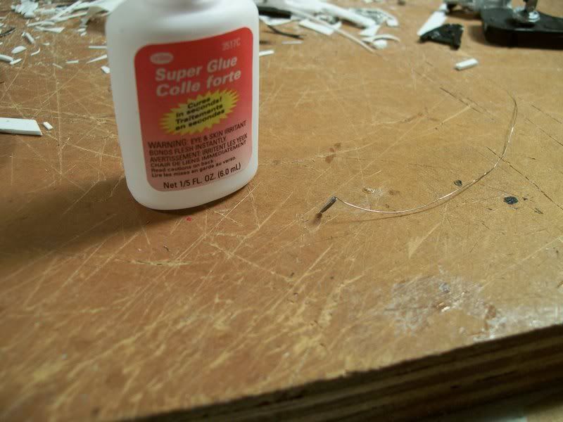 As you can see, there are now two core wires in place (you have to thread them as you go), as well as a longer piece of tubing. Coming together (all this took about 10 minutes. The diagrams took about 30. It's not that hard). 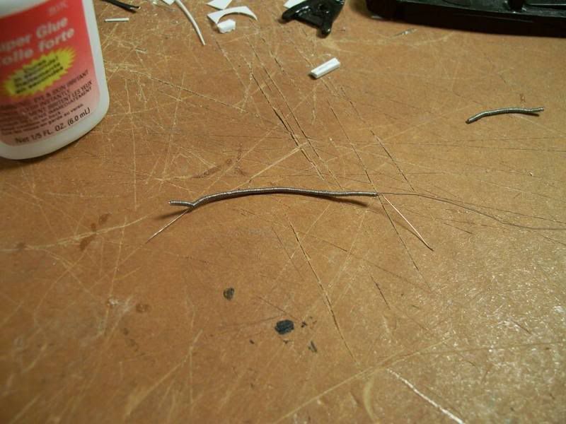 More wires and tubing; this shot shows a section of .41mm tube that I made: it's the one sticking out to the left. 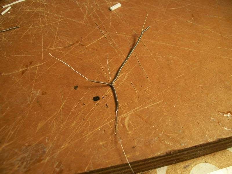 You get the idea by now; if not, don't worry. For some reason, despite being old, the '69 Firebird has a convulted tubing harness, but is much simpler. I'll make a very detailed tutorial of that (maybe showing my fingers putting the pieces together  ) that will hopefully clear up any confusion. ) that will hopefully clear up any confusion.Here's the finished harness, with all the stubs (I just cut scraps of leftover .13mm wire for them; slipping them into the proper section of tube and supergluing in place, then trimming excess length). You'll notice that it is stiff and straight, like my 1:1 size chart, because I cut all the tubing segments to length based on that. Each time a wire comes out of the harness, whether to connect to a component or to start a new branch, the tubing of the harness ends and a new segment is installed on the other side of the branching wire. That's the basic concept behind this. 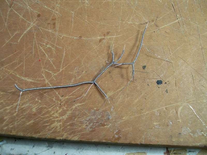 I fitted the harness into place (it protrudes through bulkheads and goes all over the place) to get the shape right, then brushed on semi-gloss black. (I also used a little Bare-Metal foil to hide the joints where wires protrude and the tubing stops; you can see the core wires at those locations. The foil looks like the tape used on real cars in those very locations, so it's all good. 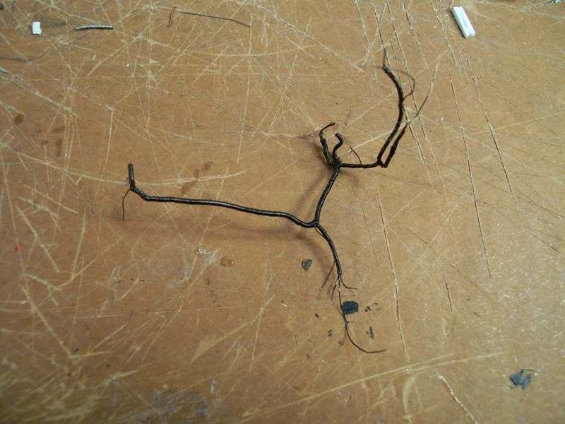 Voila, a harness. I know that was long and complex, but as you can see, the results are great. Now it's just "Plug and Play." (well, I have to make some connectors from styrene, too). Now, here are some shots I tried to do before, but this time with my new camera. (In other words, not blurry). The 16-piece ABS modulator, and corresponding brake lines. 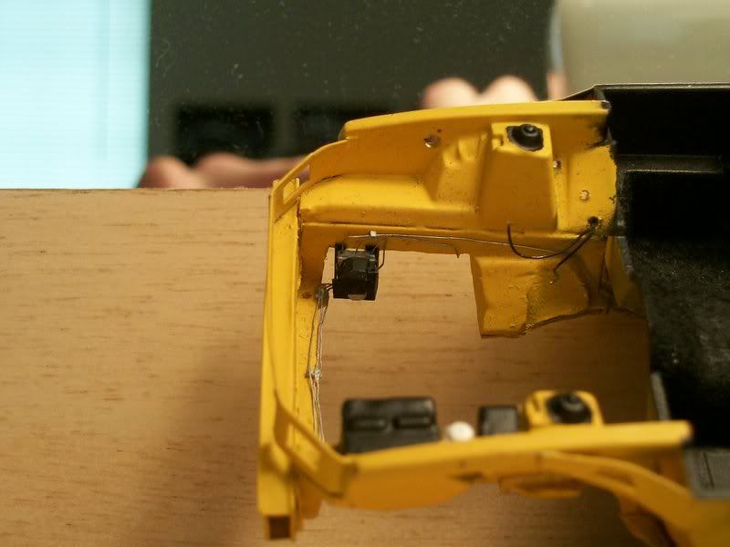 Scratchbuilt structural parts (radiator core support, bumper, etc.) 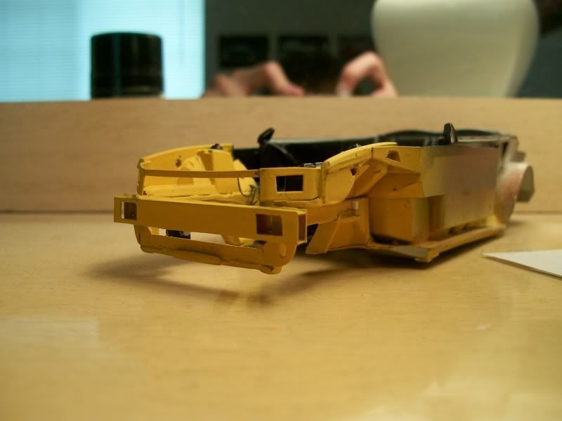 Body, painted, clear coated, and polished with 3200, 3600, and 4000 grit MicroMesh and then Tamiya fine and finish compound. It's a little imperfect because: 1. When I first started this restoration, I didn't know about paint stripping, and used a flat knife blade to remove some of the paint  . The resulting chips and dings were partly filled in, but certainly not fixed, by primer and paint. They look like minor door dings, so no biggie (this model is of a driven, not a showroom, vehicle). . The resulting chips and dings were partly filled in, but certainly not fixed, by primer and paint. They look like minor door dings, so no biggie (this model is of a driven, not a showroom, vehicle).2. I failed to remove some bits of flocking that had collected on the body before I clear coated. They are now trapped under the clear coat. They look like road tar, so no biggie. 3. Testors spray cans suck and there was bad orange peel. It didn't all come out with polishing. On the other hand, Ford's factory paint jobs aren't all that great, either, so no biggie. From now on, it's Tamiya only, and the clear will be airbrushed. The spoiler has to be repainted, and the trunk lid doesn't balance on the body (the hinges are mounted to the interior tub), so that's why they aren't shown. 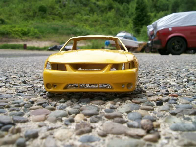 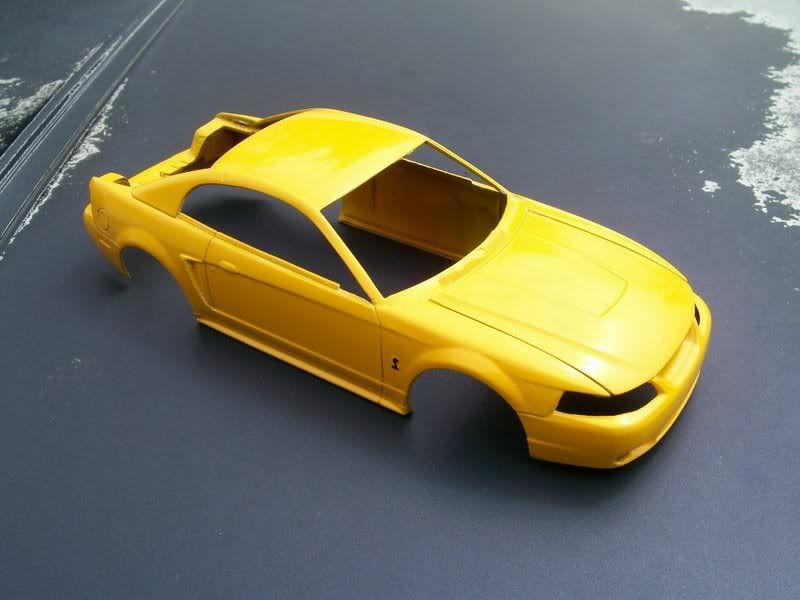 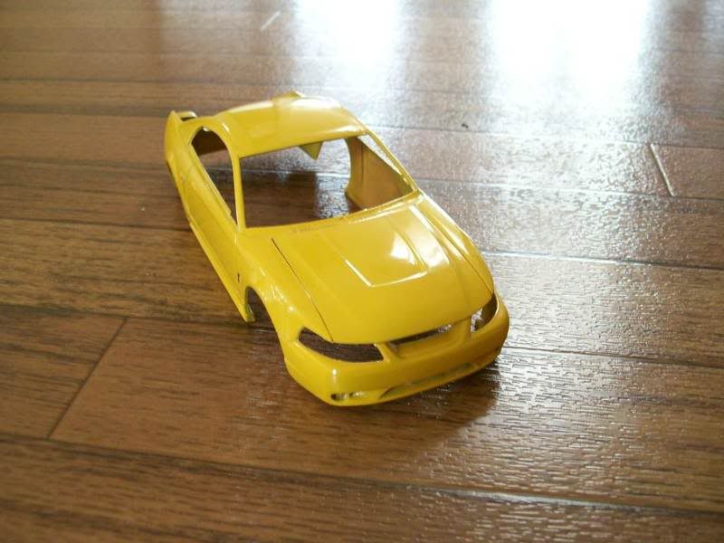 My unfinished interior, with handmade seat belt buckles. 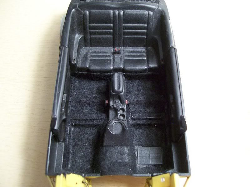 My detailed (and quite accurate) fuel and brake system. 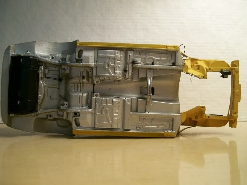 And, the engine (I took a shot of the other side, but the camera focused on the wrong spot and I didn't notice until everything was put away. You get the idea). 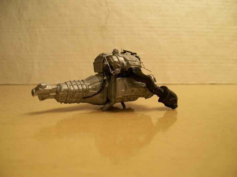 Look for more updates as I try to finish this, and my loathesome Firebird, during the short summer. Thanks for looking! Alex
__________________
|
|
#10
06-19-2007, 02:43 AM
|
||||
|
||||
|
Re: 1999 Mustang Cobra--extreme detail!
OH MY!!
 I seriously need some styrene,wires,and a dremel... I love the chassis!! I gotta tell you,your new camera made your model look sooo cleaner!!! Awesome work!!
__________________
"Oh noez,it has more stickers than me! And a wing too!
|
|
#11
06-19-2007, 01:56 PM
|
||||
|
||||
|
Re: 1999 Mustang Cobra--extreme detail!
Hell yeah, that looks so much better - the car/wiring and the pictures from a better camera! You certainly love the wiring. I like how you do this on all of your builds. BTW is the Vette finished or did I not remember seeing it finished?
|
|
#13
06-19-2007, 07:18 PM
|
||||
|
||||
|
Re: 1999 Mustang Cobra--extreme detail!
Quote:
__________________
|
|
#14
06-23-2007, 05:24 PM
|
||||
|
||||
|
Re: 1999 Mustang Cobra--extreme detail!
A small update: I installed the fuel filler pipe. This is a piece of ordinary rubber-coated electrical wire (probably from a car, I don't remember where I got it). Still working on the engine and chassis.
 Thanks for looking. Alex
__________________
|
|
#15
06-24-2007, 02:16 AM
|
||||
|
||||
|
Re: 1999 Mustang Cobra--extreme detail!
Nice stang, although it is a supra's lunch, dinner, breakfest. Lol, keep up the nice build!!!
|
|
|
POST REPLY TO THIS THREAD |
 |
|
|