|
|
| Search | Car Forums | Gallery | Articles | Helper | Air Dried Fresh Beef Dog Food | IgorSushko.com | Corporate |
|
#1
 08-22-2011, 06:30 AM
|
|||
|
|||
|
F1 Suspension geometry
Just a wild throw it out there and see what comes back sort of question.
Does any one have details of the Castor, Camber and Toe angles used on both the front and rear of the road converted GTR's, failing that any variant of the F1? Thanks in advance to all the experts out there. 
|
|
#2
08-22-2011, 04:47 PM
|
|||
|
|||
|
Re: F1 Suspension geometry
Well according to the copy of what looks like Gordon Murray's hand written notes on page 127 of driving ambition (I assume this is for the road car only due to it's placement in the timeline of the book) it looks like the castor is 4 degrees and camber is -45 minutes which means 0.75 degrees. The camber change is 4.4 degrees for 80 mm of travel. The King Pin Inclination is 9 degrees and toe in is 3 mm in front and 0 at the rear. If anyone can correct any numbers i have please do so.
|
|
#3
08-23-2011, 04:26 AM
|
||||
|
||||
|
Re: F1 Suspension geometry
That gives an idea, but I think the road-going GTR's were a touch different
__________________
Instagram/
|
|
#4
08-23-2011, 01:41 PM
|
||||
|
||||
|
Re: F1 Suspension geometry
Although this is 97 spec GTR that run at LeMans, it maybe usefull as a comparison.
Castor 4 degrees. Camber......... front 3.1 degrees..........rear 1.0 degrees. F/toe 1mm out per wheel. R/toe 2.5mm in per wheel Ride height front 64mm..........rear 84mm All dims, with driver on board.
|
|
#5
09-26-2011, 03:50 AM
|
|||
|
|||
|
Re: F1 Suspension geometry
The factory settings on the road car were:
Caster - 4 deg (fixed) Kingpin incl. - 9 deg (fixed) Mech. Trail - 19 mm Camber - 1.75 deg (F); .75 deg (R) (fixed) Toe - 1.5 mm out (F); 2 mm in (R) (per corner)
|
| The Following User Says Thank You to tortoise For This Useful Post: | ||
Peloton25 (09-27-2011)
| ||
|
#6
09-27-2011, 06:31 AM
|
|||
|
|||
|
Re: F1 Suspension geometry
Many thanks, just one point what is mech trail?
|
|
#7
09-27-2011, 06:43 PM
|
|||
|
|||
|
Re: F1 Suspension geometry
Quote:
 Mechanical trail is the distance between (imaginary) intersection of steering axis (line through the ball-joints) and center of contact patch when the vehicle is stationary. When the vehicle is moving forward, the center of the contact patch migrates towards the rear by several mm. The distance between the center of the contact patch when the vehicle is static and the center when the vehicle is moving is called "pneumatic trail". Pneumatic trail and mechanical trail together are total trail.
|
|
#8
09-28-2011, 02:53 PM
|
|||
|
|||
|
Re: F1 Suspension geometry
Of course must be going senile, know what it is just could not remember what the terminology was for it.
Thanks
|
|
#9
11-08-2011, 10:57 AM
|
||||
|
||||
|
Re: F1 Suspension geometry
Does anybody know anything about this coilover kit for the F1?
http://www.lmpcars.com/tag/fine-attitude/page/2/ 
|
|
#10
11-08-2011, 01:43 PM
|
||||
|
||||
|
Re: F1 Suspension geometry
I'll try to find where these were posted before to help you out
 ETA try here [although the pictures are down]
__________________
Instagram/
|
|
#11
06-28-2013, 04:10 PM
|
|||
|
|||
|
Re: F1 Suspension geometry
I could not find a more relevant thread than this for this observations (moderators if there is one feel free to move as appropriate).
I was going through my pictures of the front upper a arm and realized that there is not just two (street and race), but rather at least 4 different variations on the upper a arms. It is interesting how one car can have so many design iterations for one part. Are these parts engineered by the race teams instead of McLaren? Are there any street cars with the race type upper a arms? 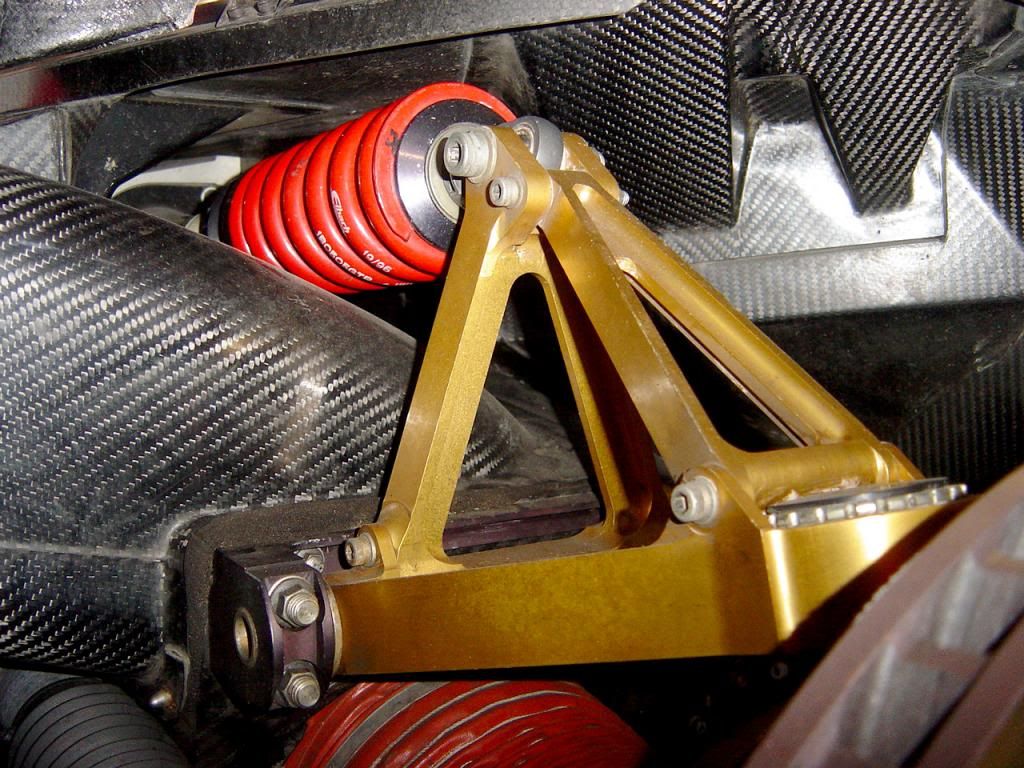 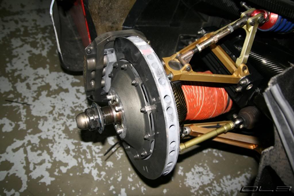 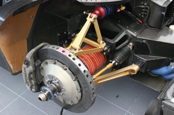 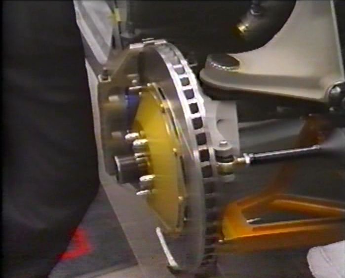 
Last edited by webslinger283; 06-29-2013 at 08:14 AM.
|
|
#12
06-29-2013, 04:13 AM
|
||||
|
||||
|
Re: F1 Suspension geometry
Not sure - they might be too big? Host them somewhere and use the [IMG] tags to embed. If they are huge, link to the thumbnail for convenience.
>8^) ER
|
|
#13
06-29-2013, 08:14 AM
|
|||
|
|||
|
Re: F1 Suspension geometry
Thanks Erik, I realized after your post I was trying to post using the page URL and not the image URL. My delinquency has been corrected.
|
|
#14
07-01-2013, 06:33 AM
|
|||
|
|||
|
Re: F1 Suspension geometry
The one I am most familiar with is in Pic 3 Pic 2 seems to be a modification by the teams to add extra adjustability. Not sure where 1 sits possibly on 1997 cars? Pic 4 is certainly road car and to my knowledge never used on a race variant though you can never be certain once converted for road use?
|
|
#15
07-01-2013, 09:07 AM
|
||||
|
||||
|
Re: F1 Suspension geometry
Quote:
Some GTR,s are still fitted with the road car upper wishbone, 10R being one of them The first change to a CNC upper front wishbone, was at Lemans 95 then there were two further variants for 96 and 97. Nothing unusual in this, geometry and component changes dictating the main reasons for these updates.
__________________

|
| The Following User Says Thank You to Le Man For This Useful Post: | ||
hurstg01 (07-01-2013)
| ||
| ||||||||||||||||||||||||||||||||||||||
 |
POST REPLY TO THIS THREAD |
 |
|
|


