|
|
| Search | Car Forums | Gallery | Articles | Helper | Air Dried Fresh Beef Dog Food | IgorSushko.com | Corporate |
|
|||||||
 |
 Show Printable Version | Show Printable Version |  Subscribe to this Thread
|
|
|
Thread Tools |
|
#1
 04-24-2008, 11:56 AM
|
|||
|
|||
|
1.9L starter motor wiring - further discussion
Not worth reading unless you're particularly interested in matters electrical - just some further discussion arising from this thread, in which the following point was raised:
Quote:
The quick answer is that the relay coil and the starter 'Hold' winding form what's known as a 'potential divider' circuit, in which the resistance of the relay coil will exceed the resistance of the Hold winding by a considerable ratio - at the very least, I'd say 40:1 but it may in reality be a much higher ratio. The voltage will be split proportionately, leaving very little voltage across the Hold winding and that's why it isn't able to energise the coil sufficiently to engage the solenoid plunger during normal running. That's the quick answer, but to explain it in greater detail, here's a quick guide to basic resistive potential dividers: If you take two (or more) resistors and place them in series across a supply voltage, the voltage will be split between them. Fig.1 shows a supply voltage of 12V, with two resistors of equal value connected in series across the supply rails. Because the resistors are of equal value, the voltage will be divided equally, with 6V being dropped across one resistor and 6V across the other. I'll use resistance values of 100 ohms, but the values could just as easily be, say, 50,000 ohms - provided the resistances are equal, the voltage will be divided equally (the current flowing in the circuit would of course reduce if using 50 Kohms instead of 100 ohms, and in real-life, the resistor values would be chosen to suit the particular application). Fig.1 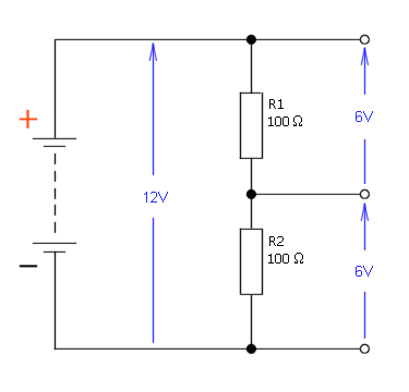 Fig.2, below, shows the same 12V supply rail, but this time with unequal values of resistance. The upper resistor, R1, has been increased to 300 ohms, while the lower resistor, R2, is still 100 ohms. The supply voltage will be divided proportionately, and thus R1 will have 9V dropped across it and R2 will have 3V across it. Fig.2 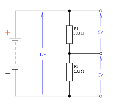 So that illustrates the way that the voltage is split proportionately to the resistance values in a simple resistive voltage divider, but just to verify that my assumption of having 9V across the upper resistor, R1, is correct, let's do the calculation: VR1 (i.e. the voltage across R1) = Vsupply * R1 / (R1 + R2) VR1 = 12 * 300 / (300 + 100) VR1 = 3600 / 400 VR1 = 9V If we have a supply voltage of 12V with two resistors in series and we're dropping 9V across R1, then the voltage across R2 must be 12V - 9V = 3V, but let's just confirm that again by calculation: VR2 (i.e. the voltage across R2) = Vsupply * R2 / (R1 + R2) VR2 = 12 * 100 / (300 + 100) VR2 = 1200 / 400 VR2 = 3V And so we do have the voltage split as predicted: 9V across R1, and 3V across R2. So, enough about voltage dividers - let's look again at the circuit comprising the relay coil and the starter Hold winding. The relay coil and its parallel suppression resistor are shown as Rcoil and Rs in Fig.3. Turning now to the starter assembly, I've been referring to the current as flowing through the Hold winding for the sake of convenience and to avoid unnecessarily complicating matters, but if you look more closely, the Pull-In winding and Motor windings (both in series) are in parallel with the Hold winding. Current will therefore flow through that complete network instead of flowing through just the Hold winding alone, so the circuit looks like this: Fig.3 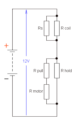 If we knew the values for the relay coil and its parallel suppression resistor, we could calculate the effective resistance and represent them by a single resistor, which is shown as Rrelay in Fig.4, below. Similarly, if we had the values for the Pull-In winding and the motor windings, we could calculate the series resistance, and then calculate the effective resistance when that is placed in parallel with the Hold winding, and represent the total resistance of that series-parallel starter network by a single resistor, shown as Rstarter, below. Fig.4 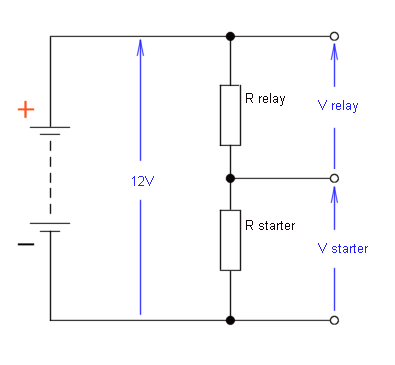 So the simplified circuit boils down to nothing more than a simple voltage divider with two resistors in series across a 12V supply, which takes us back to where we started, and if we use my estimate (and I reckon that's a conservative estimate) of the relay coil (with its parallel resistor) having a resistance at least 40 times greater than the starter network resistance, and knowing that the (nominal) supply voltage of 12V will be divided proportionately between the two resistances, then the voltage across the relay will be: Vrelay = Vsupply / 41 * 40 Vrelay = 12 / 41 * 40 Vrelay = 0.293 * 40 Vrelay = 11.71 and the voltage across the starter network will be: Vstarter = Vsupply / 41 * 1 Vstarter = 12 / 41 * 1 Vstarter = 0.293 * 1 Vstarter = 0.29 (Both answers rounded off to two decimal places). So the voltage distribution would be something like this: Fig.5 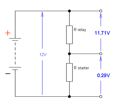 So, from the supply voltage of 12V, 11.71V would be dropped across the relay, and the remainder of just 0.29V dropped across the starter, and that is the reason why they have been able to configure the circuit in the way that they have. The voltage across the starter network is far too low to cause either the Pull-In winding or Hold winding to actually move the solenoid plunger, and also far too low to cause the motor to rotate, although a weak magnetic field will always be present in all three components whenever the key is in the Run position - i.e. during normal driving. Interesting stuff eh, or maybe not, depending on your point of view, but I don't ever get bored of volts and ohms and amps. 
|
|
#2
04-29-2008, 05:22 AM
|
|||
|
|||
|
Re: 1.9L starter motor wiring - further discussion
Thanks Selectron for that very good explaination of that starter and fan relay circuit! That definitely was very interesting stuff!!! I certainly appreciated it because I think about stuff like that and try to apply it to repairs. I also had a few courses on it, but wished more stayed with me.
 Two questions I have are, why do they need two coils on the starter as I've seen them with just one, Two questions I have are, why do they need two coils on the starter as I've seen them with just one,  and why do they need the diode going from ground to hot+, something to do with the motor? I've seen that in several applications, but never knew why. and why do they need the diode going from ground to hot+, something to do with the motor? I've seen that in several applications, but never knew why.I bet you also like inductance, impedance, capacitance, pcbs, logic circuits, silicone stuff, those tiny little e- things... 
|
|
#3
05-01-2008, 02:38 AM
|
|||
|
|||
|
Re: 1.9L starter motor wiring - further discussion
My understanding of the use of two coils in the solenoid is that it reduces the current consumed by the solenoid, thereby maximising the current available to the motor for the more important task of cranking the engine. Any solenoid or relay will have a specified minimum pull-in voltage required for consistent and reliable pull-in, but after pull-in has been achieved, the voltage (and hence the current) can be reduced considerably provided it remains within the 'hold-in' voltage window.
If using only a single coil, the solenoid current would remain at the higher pull-in level for the entire duration of cranking, but with two coils the higher pull-in current only flows very briefly while the solenoid plunger travels the short distance from its rest position to its pre-engaged position where it is meshed with the ring gear. At that point the contact disc will bridge the B and M terminals (and thus the motor will run) but also that will cause a short-circuit across the pull-in coil (12V on the high end from the S terminal, and also 12V on the low end from the B terminal) - thus it will no longer be energised, leaving just the Hold winding energised by the 12V from the S terminal. The Hold coil will have a much higher resistance than the Pull-In coil, meaning less current flow and thereby freeing up some current to be used by the starter motor. I think it's the case that they're not necessarily two separate windings, but they can be a single coil with a tap part way along its length, and that tap point would connect to the S terminal and become the 'high' end of both coils. Unfortunately, coil resistance values and the coil phasing are not normally included on wiring diagrams so the action isn't always clear, but I reckon that's why they use two coils instead of one. The diode point is a much more interesting one, because it's reverse-biased so it looks like it would never pass current and would never serve any useful purpose eh. As we know, a diode will pass current when forward-biased, i.e. anode positive with respect to cathode, but it will block the flow of current when reverse-biased, i.e. cathode positive with respect to anode. Device symbol: 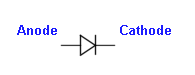 Component marking: 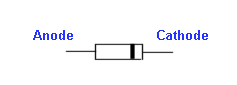 The reason why a diode is in the circuit is because the circuit at that point contains an inductive load - three of them actually - the two solenoid coils and the motor, and when you break the current flow in an inductor - i.e. switch off the current which feeds the inductive device, something called back-emf (electromotive force) is generated and this will have a polarity which is opposite to that of the supply voltage. The amplitude of this back-emf, or voltage spike, can easily reach hundreds, even thousands, of volts, even when fed from a low-voltage source. This spike obviously has the potential to damage semiconductors in the circuit, so measures are taken to suppress it. A number of methods are used but most commonly it's dealt with by adding either a reverse-biased diode, or a resistor, in parallel with the inductive component. Both methods can be seen in the 1.9L starter circuit - a single reverse-biased diode is utilised to kill the spikes from all three inductors in the starter assembly, and a parallel suppression resistor absorbs the spike from the coil of the Cooling Fan Power relay. The amplitude of the spike which will be induced in any given circuit can be readily calculated if three factors are known: the inductance of the coil, the amplitude of the current flowing through the inductor at the instant of switch-off, and the time taken for that current to collapse to zero. The numbers are then slotted into the formula for self-induced back-emf, which is: e = - L * di / dt where L is inductance (the standard unit for which is the 'Henry'), di is the change in amplitude of the current (in amps), and dt is the time taken for the current to collapse to zero (in seconds, but in practice that would typically be mere milliseconds). The interesting thing about that formula is that the supply voltage simply isn't a factor, and thus considerable back-emf - even several thousand volts - can be generated from the lowest of voltages if the other conditions are met - large value of inductance, high current flow, and fast switch-off. In auto-electrics, reverse-biased protection diodes are commonly utilised on DC motors, where they would look like this: 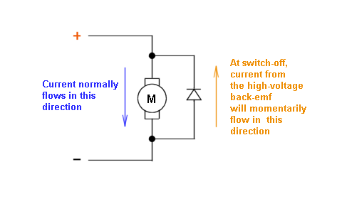 When a diode is forward-biased, it has a voltage drop of around 0.7 volts, increasing slightly as current increases. In the circuit above, the diode is reverse-biased during normal operation and thus plays no part in the proceedings. At the instant of switch off though, the magnetic field in the motor's (inductive) windings will collapse, and the stored energy will be released in the form of back-emf - a voltage spike with a polarity which is the reverse of the supply voltage. The diode will thus become (very briefly) forward-biased and will limit the amplitude of the spike to a safe level. In the case of the Cooling Fan Power Relay in the 1.9L, a suppression resistor is fitted in parallel with the (inductive) relay coil. Under normal working conditions when the relay is energised, some current will flow through the coil, from high end to low end, and some through the parallel suppression resistor - which at this point serves no useful purpose. Upon switching the relay off though, a voltage spike will be induced, which will find a ready discharge path through the parallel resistor, which dissipates the power as heat. In the commonly-seen arrangement whereby a relay is used to power a DC motor via its switched contacts, spike suppression would be required at two points in the circuit - at the relay coil to suppress the spike generated there when the coil is de-energised, and then also at the motor to suppress a quite separate spike which is generated simultaneously when the magnetic field in the motor windings collapses at switch-off. In that case, you would probably find a resistor in parallel across the relay coil, and a reverse-biased diode in parallel across the motor. The reason for the suppression in all cases is to protect the rest of the circuitry from the high-voltage spikes, particularly the voltage-sensitive semiconductors within the electronic control modules, CD player, radio, etc., and also to prevent those spikes from causing radio frequency interference (RFI) on the AM band of the car radio (electrical noise is less of a concern on the FM band, because the frequency modulation process gives the signal a high inherent noise immunity). Well, that turned into a much longer post than I intended so I'll quit there and go and make some breakfast and start the day.
|
|
|
POST REPLY TO THIS THREAD |
 |
|
|


