|
|
| Search | Car Forums | Gallery | Articles | Helper | Air Dried Fresh Beef Dog Food | IgorSushko.com | Corporate |
|
|||||||
| WIP - Motorsports Post topics for any "Work In Process" motorsports vehicles in this sub-forum. |
 |
 Show Printable Version | Show Printable Version |  Subscribe to this Thread
|
|
|
Thread Tools |
|
#31
 02-12-2003, 04:46 PM
|
||||
|
||||
 Beautiful shine! Now we just need some pics with the lights on in this new paint job. Beautiful shine! Now we just need some pics with the lights on in this new paint job. 

|
|
#32
02-12-2003, 05:22 PM
|
||||
|
||||
|
Looks amazing!!!
How did u end up making it into the road version i.e minus the GT wing?
__________________
CHRIS... Catch me on FACEBOOK http://www.c1-models.com http://www.facebook.com/C1Models
|
|
#33
02-12-2003, 06:38 PM
|
||||
|
||||
|
Fan-smeggen'-tastic.
I was wrong about prefering the competition variety - your road version is a one of a kind! Take it you scratch built the rear wing?
|
|
#34
02-12-2003, 06:41 PM
|
||||
|
||||
 That Benz is beautiful and I love the 350Z. Great job. That Benz is beautiful and I love the 350Z. Great job.
|
|
#35
02-13-2003, 12:26 AM
|
||||
|
||||
|
thanks for the kind comments. i haven't reinstalled the bulbs for the lights just yet. so pictures of that won't be around for a while.
fly, i just call it road version only for the fact that i destroyed the competition decals. so... i guess you could call it a gt car without the sponsors and the gt wing 
|
|
#36
02-13-2003, 12:31 AM
|
||||
|
||||
|
nice wow... u really work well with the decals....
__________________
AF OG Dori crew (member #5)  Altezzas: It only looks good if you have the FULL car, not just the LIGHTS!! grinyes:
|
|
#37
02-13-2003, 02:19 AM
|
||||
|
||||
|
lights
i took down this post because i wanted to redo it and add a bit on diodes but here it is again.
1)the battery pretty straight forward. you might want to buy a smaller one as they do have those. i just chose this one only because the smaller one is alot smaller and may prove difficult to create an adequate housing for it.  2) the battery case this thing was built using plastic sheet: 1mm on each side to make the initial housing. then using a fresh blade, score down the center of the sides where the wire is to go. this would give you a guide as to where you need to make holes with the pin vise and above all else, to make a groove so that the wire can lay down flush with the surface and allow for a level surface for the next step. when you finish snaking the wire through, two layers of 0.3mm plastic sheet was laid on top to cover the wires and to provide some support and a flat plastic surface on which to glue with. 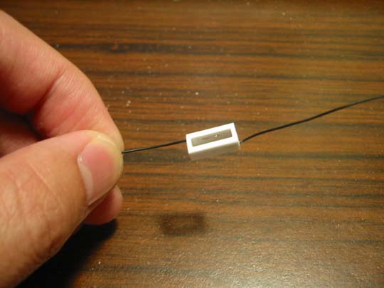 3) the power source this is how the battery fits into the battery casing. i suggest making a narrow casing such as the one in the picture so as to make changing the battery that much easier. 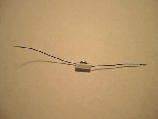 4) the headlight housing using a pin vise, carefully drill a hole through the back of the headlight piece. if you aligned it right, you would drill out the center of the headlight and push the 'nipple' out from the center of the housing without damaging the sides. after this, use a qtip to brush away the plastic before you use a 1/16 drill bit to make the hole large enough to accept the bulb. 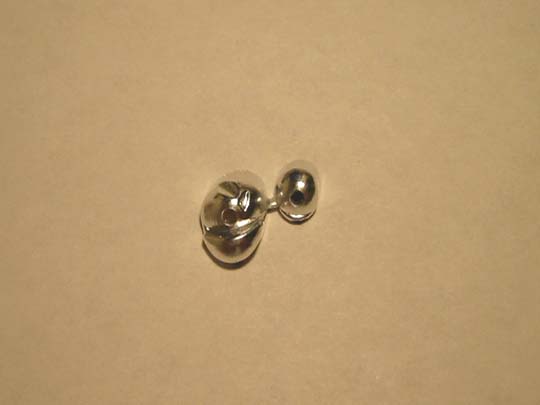 5) the bulb unfortunately, i don't have a caliper so i cannot tell you what the diameter of this guy is. what i can tell you is that it is smaller than a 1/16 drill bit... but not by much. the electrical specs on this bulb is: 1.5v 30mA 45mW. this means that you can use any 1.5v battery to power this guy. as this thing draws a very low amount of current, the power consumed is only 45mW and is nothing to be concerned about. 45mW is not going to hurt the paint nor distort the plastic. after running the bulb in the housing for over 5min, the bulb did not even feel warm. remember this thing is small and does not heat up to any cautionary level at all. these bulbs are usually used for model railroad cars. thus they have a variety of colors that include green, yellow, white, and red. they come two levels of rated use: 1000hrs and 800hrs. they are a bit expensive as they run about $1.50 each for incandescent bulbs this size. when you insert the bulb in after the holes are made, the bulb fills the hole quite well and will appear to be 'invisible' and blend well to the plated housing. i would suggest epoxy putty or two part epoxy (be careful of the amount as they do heat up when curing) to glue these in place from behind. 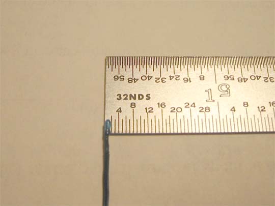 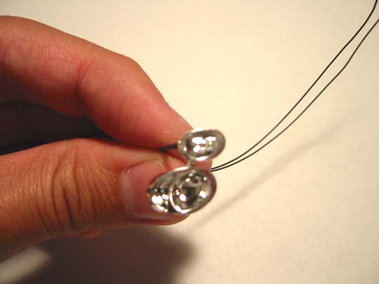 6) the layout for simplicity's sake, i left the hardware separate and placed them where they should go. the layout is quite simple for this kit. however, you have to be careful with the placement or it will rub against the air intake. depending on how large you made the source housing, you will have to profile it to fit. the connection to the switch will be covered with a plastic rod while the wires will be snaked through another smaller plastic rod which would act as a conduit. you can see the hardware though the grill but with a bit of wire mesh, the problem is solved. i used the smallest switch that i can find and it still is a bit big. it still works but is very snug. 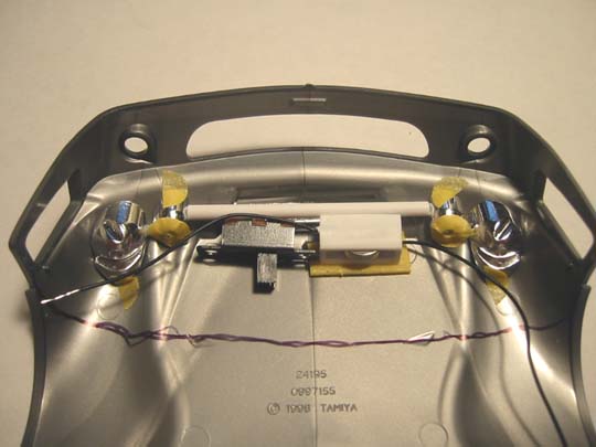 7) the outcome so this is how it will look. it is worthy to note here that the position and angle you place the bulb will affect the way the light shines. 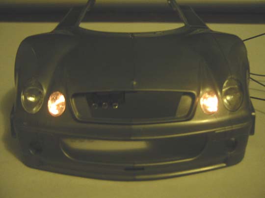 8) diodes there has been a lot of talk about the use of leds and that of a true led. im going to dispel the belief that there is anything such as a true led. (those with an engineering background may want to just end here as you may already know this.) some claim that there is a magical voltage on a true led and so forth but the fact of the matter is that leds are simply a special form of diode. traditional diodes turn on at 6.3 volts and allows current to flow in one direction only. However, technology has enabled countless other on voltages today which gives us more flexibility and variety. any further discussion on the operating voltage is moot since technology has enabled the existence of diodes and leds with operating in voltages as low as 1.6v and up. that is it. nothing more. you just have to be careful and ask questions regarding their range of operation when buying these leds. This is one variable you can control in creating the circuit that you want. now, the burning question that you all have is what type of voltage does it run on and does the circuit need a resistor. Ill try to give you a cohesive answer to this question. conveniently, for me the question is that it all depends. it depends on the choice of circuit that you decide to use and the voltage supply that you have available to you. Ill talk about the source and leds first. for the 350z, I have a 9v source (battery size 25A is 9v and 27A is 12v). the 9v source is very hard to come by but I have seen on occasion the 12v source at radio shack. the 12v source is a bit bigger thus the 9v is more desirable. You can always make the 12v source work but it gets a bit tricky with the limited amount of space available to incorporate lights on many of the model kits today. The leds that I chose for the 350z utilizes two white leds with a published typical operational voltage of 3.0v and two red leds with a published typical operational voltage of 3.0v as well. You guys may be scratching you heads now how did he get four leds which add up to 12v required on voltage to run on 9v? heres the answer. Published operational voltages (voltage ranges or swings) are the voltages that engineers and others would normally run at to account for voltage variations and voltage spikes. A 3.0 volt led with a published operational voltage may have a true turn on voltage anywhere between 1.6v to 2.8v and a typical maximum voltage of 4.5v. most packages publish absolute max and absolute min operating voltages. These are the absolute minimum required voltages needed to turn the led on and the maximum voltage that these diodes will operate reliably. Anything higher than the absolute max voltage would pop the led immediately or dramatically decrease the mtbf exponentially. The white leds that I use have a true turn on voltage of 2.8v and the red leds have a true turn on voltage of 1.6v. note that light intensity is a direct function of the voltage drive. If you want it brighter, bump up the voltage but remain in the manufacturers recommended range (otherwise, youll end up swapping out the leds for fresh ones). In this case, 2*2.8=5.6v for the white leds and 2*1.7=3.4v for the red leds. This adds up to 9v exactly. So I dont need resistors in my circuit to operate the leds reliably. My series circuit is shown below (the source and housing is right above the switch): 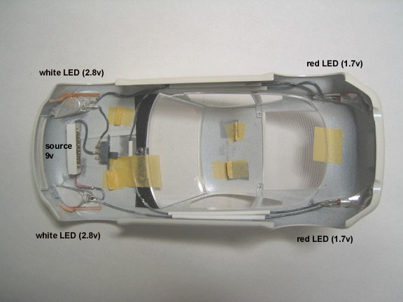 Now, if you are running two white leds with a typical operational voltage of 3.0v with a 9v souce, you would definitely need a resistor even if you put them in series (Im not going to go into the basic circuit structure of series and parallel circuits when an internet search will do so more comprehensively). It is necessary to drop the voltage by at least 3v to keep the leds within manufacturers recommended operating voltages. These particular white leds use 20mA of current. Thus utilizing ohms law, v=I*r (where v=voltage needed to be dropped, I=current that the leds draw, and r=resistor value necessary to maintain reliable operating conditions for the led), 3v=(20mA)*r. this gives us a series resistor value of 150ohms. This is the resistor value that you would need to maintain 3.0v to each led. if you want to bump the voltage per led lower, just bump up this resistance value and vice versa if you want to bump the voltage higher (but remember, higher voltages mean shorter operational lifetimes). As it relates to illuminating lights for models, resistors are only needed in a circuit for this reason only. Nothing more. so, if your circuit is similar to the one I used for the 350z, you dont need resistors as they fall in a desired operational voltage. If you have leds with undesirable typical operating voltages such as 4.5v, you might need to tweek the circuit as described above to keep the leds in the operational region (depending on your source that is). A note on circuits: try to use series circuits as much as you can as this draws less power on the battery and thus extending the battery life. Heres a simple example: 10v source with two 10ohm resistors. Put them in series and you get a current draw of 0.5A while a parallel circuit with the same elements would draw 2A. thats four times as much current! Moral here, series circuits have the ability to save your battery life by as much as 4 times that of a parallel circuit. In the end, I would choose to use the incandescent bulbs for daytime running and fog lights while restricting leds to such usages as headlights and brake lamps. a.
|
|
#38
02-13-2003, 03:28 AM
|
|||
|
|||
|
It turned out very nice! Nice paintwork!!
I'm in favour of a more used and dirty look of engine bays. Clean engines don't exist in my world  Anyway, I think your instructions on how to make lights, should be in the Tutorial that they aer working on. Jay?
|
|
#39
02-13-2003, 03:38 AM
|
||||
|
||||
|
Impressive!
Everything looks great, from the beautiful interior and engine details to the smooth and shine paint job. Excellent work.
|
|
#40
07-14-2003, 09:37 AM
|
||||
|
||||
|
what is this poer sources ? need more info !!
__________________
 CarsModeling.com. My Scale Model Cars blog.
|
|
#41
07-14-2003, 08:04 PM
|
||||
|
||||
|
anyone know what is the power source ? the small white 9V source look perfect but i can't find any info.. any model number or part number ? name ? anything ?
__________________
CarsModeling.com. My Scale Model Cars blog.
|
|
#42
07-15-2003, 02:36 PM
|
|||
|
|||
|
Quote:
 
__________________
La Vecchia Signora & BMW maniac.
|
|
#44
07-16-2003, 03:31 AM
|
||||
|
||||
|
Quote:
__________________
BRET  11/07/87 - 11/11/04 *** KEITH VALLEE*** R.I.P Keith. higher then any mother fucker out there..... R.I.P homie..
|
|
|
POST REPLY TO THIS THREAD |
 |
|
|