|
|
|

|
|
| Search | Car Forums | Gallery | Articles | Helper | Quality Dog Food | IgorSushko.com | Corporate |
|
| Latest | 0 Rplys |
|
|||||||
| WIP - Motorsports Post topics for any "Work In Process" motorsports vehicles in this sub-forum. |
 |
 Show Printable Version | Show Printable Version |  Email this Page | Email this Page |  Subscribe to this Thread
|
|
|
Thread Tools |
 10-27-2005, 08:58 AM
|
#46 | |
|
AF Enthusiast
Thread starter
Join Date: Aug 2005
Location: where "sky grey" is a colour
Posts: 822
Thanks: 3
Thanked 32 Times in 29 Posts
|
Well i'm trying to not let this "master modeler" thing go to my head. I don't really see myself as that....but thanks for the laurels:-)
Don't ask me for the brand. I bought some of them at a local tool shop. They are the standard but proper stuff and come in 1mm steps. The 1mm one was a bit difficult to get and i found it at a big German model show in the end. Just don't try to save money on tools:-) The one's you'll find at a cheap DIY store prbably won't make you happy. I first used one of these things to make holes in belts but they hardly make round holes:-) If you have a lathe you can even make them in the size you need from hard aluminium or steel if you can. For plastic they're good enough. Anyway...i had to clean the plastic discs up after peeling them out of the tool :-) You can also try to cut slices off plastic rods! Toolwise i had to learn that one of the most important things to have for scratchbuilding are proper files. Most offerings you get in sets are useless rubbish. I now have a pile and still want more and they usually cost around 10 each but they are worth it! |
|

|

|
|
10-27-2005, 09:25 AM
|
#47 | |
|
Authorized Vendor

Join Date: Oct 2005
Location: Vicenza - veneto de rassa
Posts: 3,910
Thanks: 6
Thanked 47 Times in 41 Posts
|
since I not love F1 too much, I discovered that thread just now
 I read that article in 1 only breath I read that article in 1 only breath  fantastic work and a lot tech. inspiration for everyone, here. So thanks a lot 
__________________
 gio gio
|
|
|
|
|
|
10-29-2005, 03:30 PM
|
#48 | |
|
AF Newbie
Join Date: Nov 2004
Location: lyon
Posts: 18
Thanks: 0
Thanked 0 Times in 0 Posts
|
Hi there, you know how a good modeler Jaykay is but you didn't know that he's also a great photographer : reference photos of the McLaren MP4/4 are online, http://www.gurneyflap.com . I added some photos of the engine alone taken at Geneva this year, here : http://www.gurneyflap.com/hondav6turbo.html
Enjoy |
|
|
|
|
|
10-31-2005, 11:24 AM
|
#49 | |
|
AF Regular

Join Date: Jan 2005
Location: Puebla
Posts: 439
Thanks: 6
Thanked 13 Times in 3 Posts


|
JayKay:
I'm speechless, first of all, hats off! and receive all my respect. Your work in this McLaren is amazing, the detail level is incredible!, so impressive. I just can't wait to see more, I'm starving to see what you will do on the engine! Great job, CONGRATULATIONS! And welcome to this AF, it's great having people like you here. And thousand thanks for sharing. Cheers!
__________________
Happy modeling! Ramon Garcia Puebla, Mexico |
|
|
|
|
|
10-31-2005, 01:34 PM
|
#50 | |
|
AF Enthusiast
Thread starter
Join Date: Aug 2005
Location: where "sky grey" is a colour
Posts: 822
Thanks: 3
Thanked 32 Times in 29 Posts
|
Oh Remi....you're giving away all my secrets at once :-))
To gionc and agamo and everyone else...thanks! I'm happy you like it so here comes some more! I was knee deep in work on the job and didn't get to model a lot lately but here are some pictures. Turns out there was more than i thought:-)) First up a picture of my "punch and die" set for Guy. The silver one in front is a home made one. 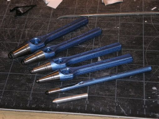 Next step on the engine is the rear suspension. The upper arms from the Tamiya box look like this: 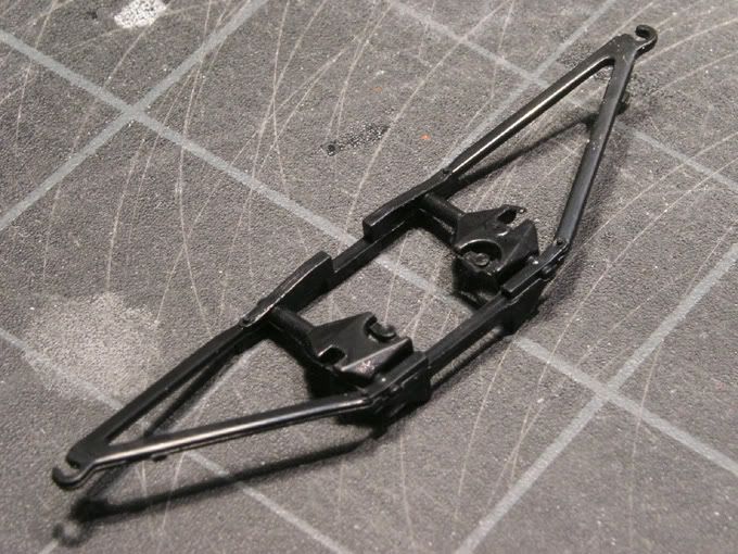 I would call that sketchy...:-) It should look a bit more like this: 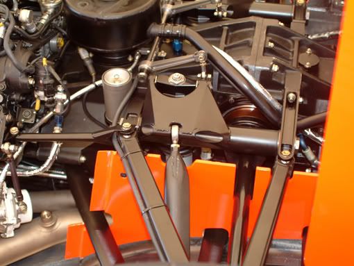 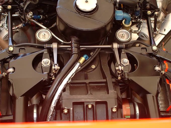 Seems there's some serious scratchbuilding necessary... I started with the mounting points and filled the holes in the gearbox with plastic bits and added some detail. Also i extended the rear end a bit where the brackets ( hope that's the right description :-) for the jack are fixed. 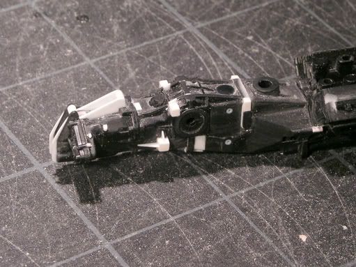 I then realized i need some brass tubes for the supension mounting points but never made it off work during shop hours so i had to stop there. Instead i worked on the turbo intercoolers. The pieces in the kit come like this: 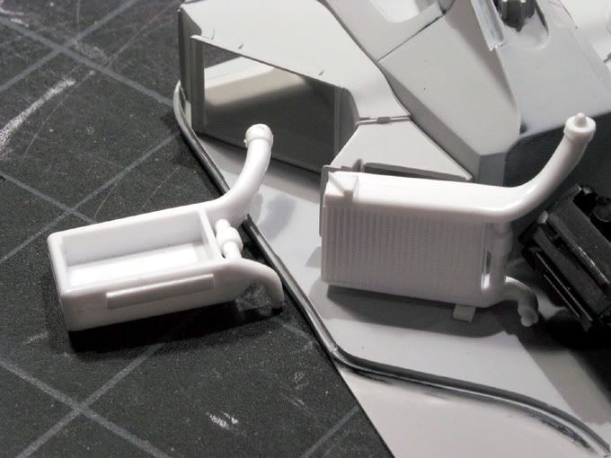 They didn't fit anymore to my scratchbuilt sidepods and needed some shrinking:-) It turned out i had to change all the dimensions and the surgery got bigger than expected. To get them positioned and connected i sketch mounted the engine and plenum chamber with tape and modelled the tube in place with bodyfiller and some lengthy filing and sanding.... 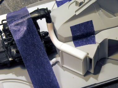 During that process i also found out the engine was sitting a bit too far to the back so i changed that as well. Here you can see a comparison shot of the untouched left radiator and the converted right one. Quite a difference. Seems McLaren/Honda improved the efficiency a lot during the season! 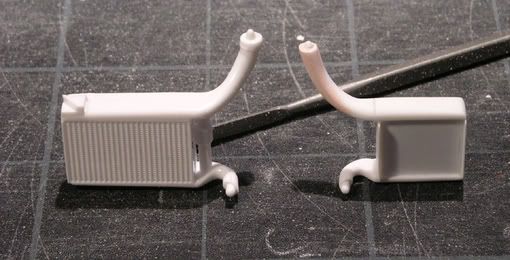 And here are both rads changed and installed. The second one was even trickier because it had to be symmetric to the other one....at least kind of :-) 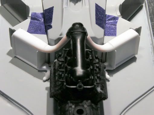 Now there need to come the radiator grills and tube connections, but these will follow after some primer to check the surfaces. During that process i also started on the rear wing. The main plane comes in two pieces: 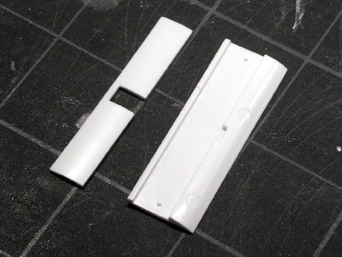 They don't fit too well but some plastic sheets and bodyfiller helped with that. Unlike the big hole in the kit pieces the original wing has two small slots for the vertical supports. 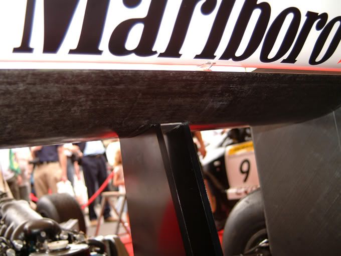 I recreated that with a piece of plastic. Some sanding on the whole surface was needed and there we go. 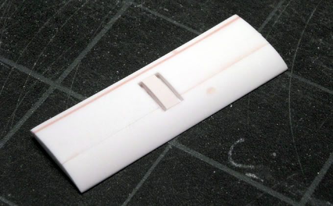 For the vertical bits i'll use the pieces i cut off from the transmisson before. They have the right thickness in this case:-) That's it for now! Let's see when i can do some shopping for the suspension:-) |
|
|
|
|
|
10-31-2005, 04:05 PM
|
#51 | |
|
AF Newbie

Join Date: Oct 2005
Location: Campinas
Posts: 74
Thanks: 5
Thanked 0 Times in 0 Posts
|
Re: Eighties Contest Entry: 1988 McLaren MP4/4 (and Introduction)
It almost seems like you don't need the Tamiya kit at all
. Great scratchbuiding and amazing results.I hope you have the will to keep building, because I think this model is going to be outstanding! |
|
|
|
|
|
12-05-2005, 03:42 AM
|
#52 | |
|
AF Enthusiast
Thread starter
Join Date: Aug 2005
Location: where "sky grey" is a colour
Posts: 822
Thanks: 3
Thanked 32 Times in 29 Posts
|
Hi everybody. I didnt have anything new to show for a while but now I have a somewhat bigger update ready, so here we go:
The next step after my last update was to make the normal radiators sitting in front of the already made intercoolers for the turbos. First heres the real one from the right hand side of the car. 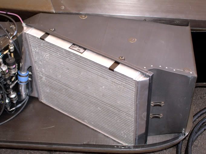 Because of the new side pods the kit pieces didnt work anymore so instead of a big ( and therefore somewhat pointless ) conversion I decided to scratch build them from plastic sheets and rods. The tube connections on the kit pieces were a bit sketchy anyway:-) 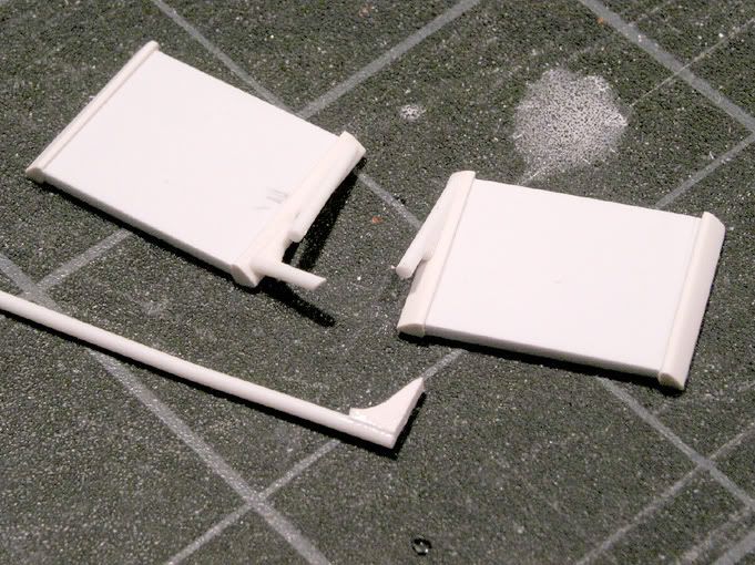 Here you can see the left one put in place and the black Tamiya one for comparison. 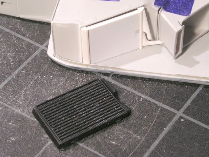 Now whats missing here is the radiator grid and thats where the reason for this delayed update comes into play:-) It was finally time to start on the photo etching! The typical PE pieces you can buy from the usual suspects in the business are mostly a selection of essential bits that you can more or less just glue on top of the plastic kit pieces. The radiator grids almost never make me happy and the other bits also leave some wishes open ( Scalemotorsport is probably the exception to the rule here ). Once you start doing bigger conversions or scratch building pieces they often become useless anyway and for some models you dont even get anything. Personally I want more than most of the available sets offer so a while back I started doing my own photo etch pieces. For the start on this one i went through my reference pictures and made a list of what seemed reasonable and feasible to make. That became a pretty long list in fact and in the end I spent 2 weeks worth of modelling time just doing the artwork. Admittedly I got carried a way in some cases but that easily happens when you can zoom into things and look at details of 1/10 mm on almost half the size of your screen :-) For those who havent seen the process yet I have taken pictures or screenshots of the process but I wont go into too much detail. First to have something to etch you need the artwork. I do mine on Freehand but other vector based software ( Photoshop is no good here ) or 2D-CAD software does the job as well. The tricky part is to decide the sizes on screen without having the possibility of testfitting what you create. A ( digital ) calliper is almost a must for this. Heres the steering wheel center during construction 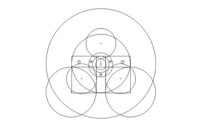 and the finished part along with two more bits that go on the backside of it: 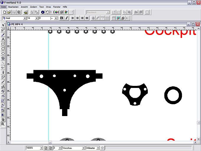 Each piece needs a front and back layer because unlike the rubber backed sheets you have come to know this process here works from both sides. Depending on the pieces the two layers are identical or different. The frontwing sideplate here has two different layers which in the end creates an elevated area ( black stripe ) on the main surface ( gray here ). 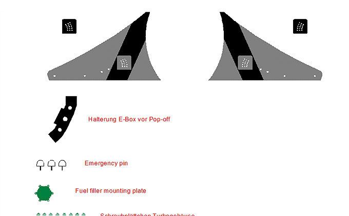 Heres an overview of all the pieces. Well actually I just realized you dont see too much in that screenshot because of the low resolution for these online pics .but you get the idea .theres quite a few :-) 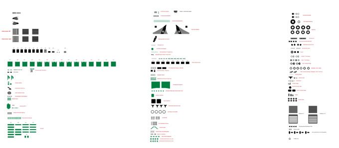 Next up after building all the pieces ( the two mounting plates that connect the camcovers with the monocoque were in fact the most time consuming pieces because everything on them is angled somehow ) i had to put them together on sprues. They are sorted by material and material thickness I can do nickel silver which comes in 0.1mm up to 0.5mm thickness and can be polished or sanded to different surface looks and brass that comes in 0.2mm up to 0.4mm and can be used for golden looking bits or blackened in a chemical solution later on which leaves a very nice metal look ( much better than paint .). For each sprue again theres a front and back side. Heres the full monty laid out . They cover a whole A3 sheet. 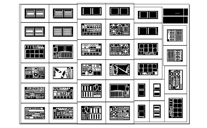 Not every single one of the bits shown will later make it onto the model. Some are double in different thicknesses or materials because Im not sure if they will work out nicely so theres a back up if one fails and in some cases I just have space on the spre left so I fill it up with pieces .you never know :-). I always try to push the limit for the sizes of elements and sometimes I go too far. This is after all a prototype run and I dont want to do another round if possible I then got this data transferred onto transparent offset film in a printing company. That is the best you can get for this purpose. You can also print it on overhead transparencies with an inkjet or laser printer but they are no match for the pro stuff in either opacity or detail. In fact a test print on a laser printer swallowed half of the fine details Here you can see the film that I got back: 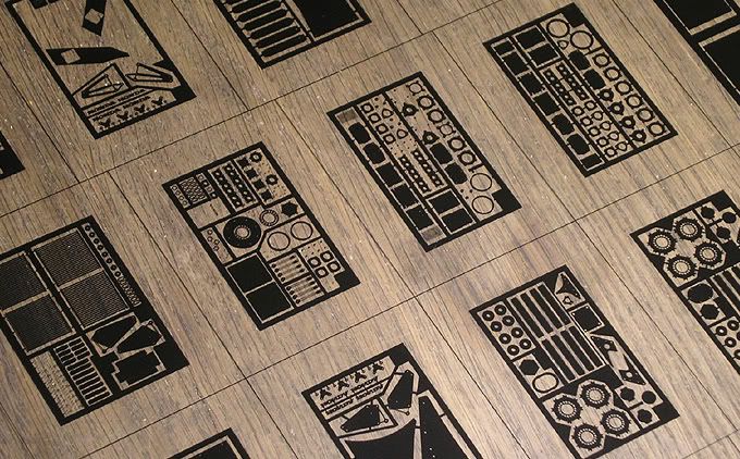 I now had to cut it up and put the respective front and back sides together with scotch tape to make little pockets: 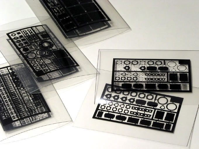 Each of them is 5cm wide. I learned previously that its better to have small sprues. Once the process goes from digital to chemical theres plenty of chances for things to go wrong and my non-pro setup etches less evenly than an industrial one. On a big sprue one corner may already be finished while the other still needs some time in the etching bath. On a smaller sprue thats just less likely:-) The next step is to cut the metal into the right size for each pocket. 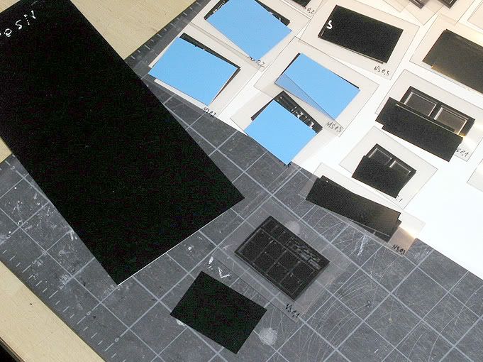 It comes pre-laminated with the photoresist ( thats the UV-light sensitive layer ) on both sides which in turn is covered with a protective film.The film is then peeled off and the metal fixed inside the pocket ready for exposure. Its easy to handle in dim light and doesnt need a darkroom. 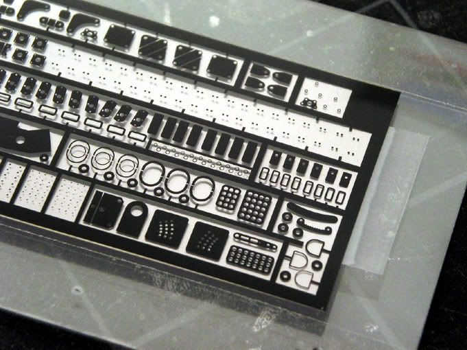 The exposure happens in this box with UV-lamps. The film pocket with metal inside is place on the glass on top of the lamps and pressed from the backside with the blue foam. Thats very important so there is absolutely no gap in between film and metal. A small buckle in the metal can already mess things up 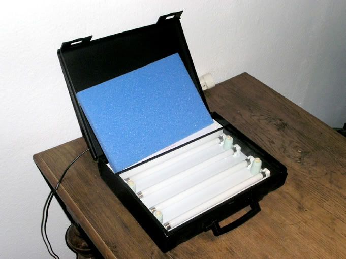 Both sides are done one after the other and then the metal goes into a developer bath for a couple of minutes. If everything goes right the result looks like this: 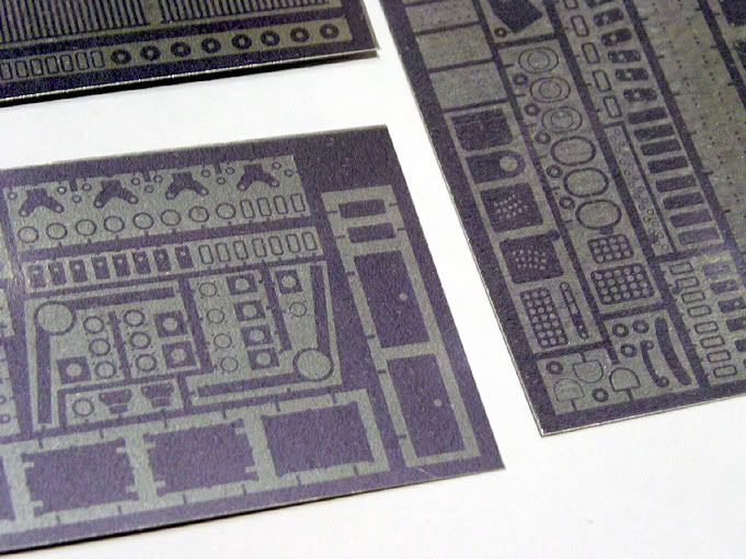 The blue stuff is the photoresist that will protect the metal during etching. The actual etching then follows in this tank in a bath of Natriumpersulfat ( you figure out what that is in English :-) at around 45°C. 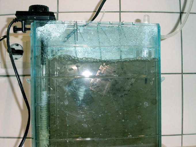 Its not exactly healthy stuff that you would give to a 12 year old but not more dangerous than some of the other stuff we work with like paint and glue. It doesnt eat fingers but has a great appetite for clothes:-) In the photo on the left side you see the heater and through the clear tube on the right comes air from a small pump that creates bubbles to move the bath. Depending on the material thickness and how fresh the bath is it takes in between 10 and 30 minutes to etch a sprue. If everything goes as planned the final result may look like this: 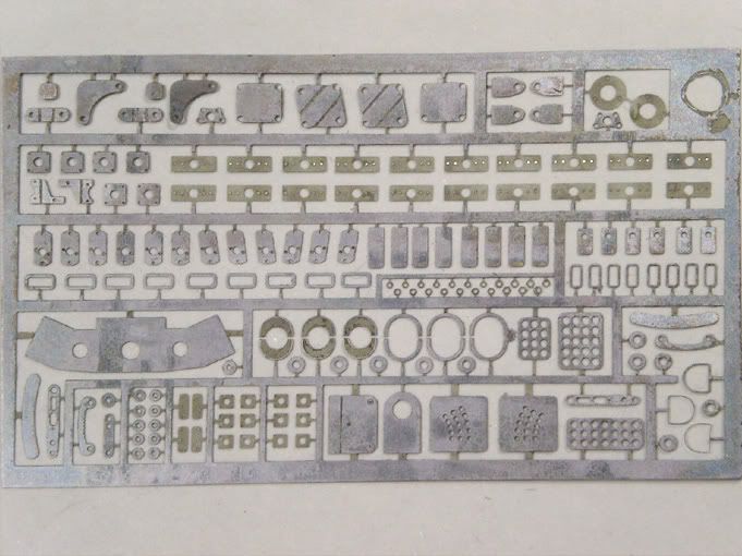 The pieces dont look as shiny as some of the ones you can buy but they will after individual treatment when I put them on the model. Im especially happy about how these radiator grids came out. Meshes of that sort are the trickiest things to make because you see every little mistake and basically cant do anything about them later because youll only bend the whole thing. 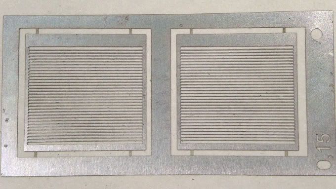 They are the best I made so far and finer than any you can buy. For reference .each of the horizontal stripes is 0.1mm high. Now I only have to get them in place without messing them up ..gulp! :-) I dont want to pretend everything was a piece of cake though. This here is a case of uneven etching: 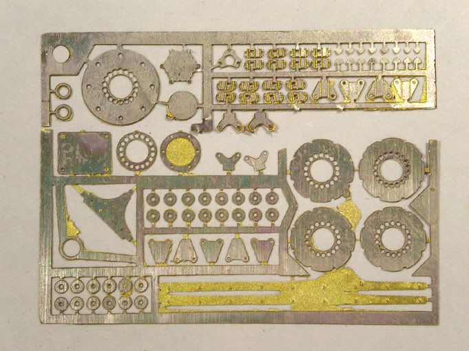 I cut the top part of the sprue off during etching to save some of the smaller bits ( otherwise they would have disappeared:-) but the rest can still be used after some filing. I also had a case that somehow went completely wrong for whatever reason but I gave it a second go and that worked. Here is an overview of all the sprues: 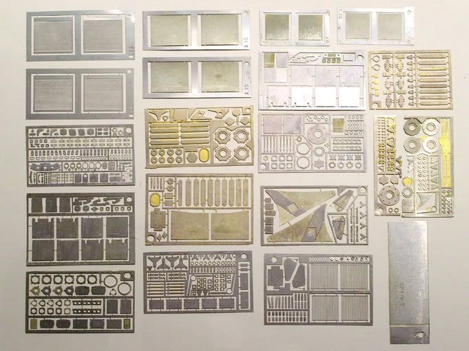 I wont get into detail what everything is. Some you can figure out easily and the rest will follow when I put them on the model .hopefully:-) For a start heres one piece that is not going directly on the model ( no its not 1/20 .its 5cm wide) !!!! :-) Its a chassis plate that I will put on top of the models box to hide the injection mark in the clear cover. The untreated piece looks like that: 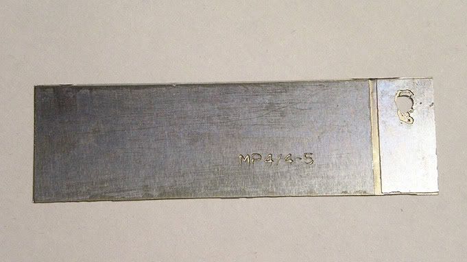 I only etched the chassis number in this case. 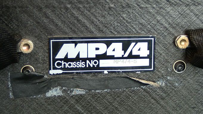 To do the black printing I rebuilt it also in Freehand using the photo as an underlay and got it made as a dry transfer ( a.k.a. Letraset ). This is simply rubbed onto the metal. I polished the metal first and then held it into the cold etching bath for about two minutes. That takes away the shine evenly and makes it look matt like the real thing! 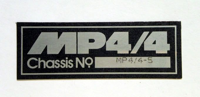 By the way ..while making all this I managed to convince David Durst of scaleracecars.com to do a run of his nice SRC nuts and bolts set in brass because they will be useful for this model and others of the same period and I couldnt find them from anyone else. They are nicer to use from a rubber backed sheet than my homemade stuff. If you are interested in them as well you may wanna get them now. Dont know if he does more .and no I dont get anything for this advertisement:-) Thats it for now! I dont know if I will do another update before Christmas but surely in the new year. Seasons greetings to everyone and a happy new year! Enjoy! |
|
|
|
|
|
12-05-2005, 03:54 AM
|
#53 | |
|
AF Enthusiast

Join Date: Dec 2003
Location: Zagreb
Posts: 2,176
Thanks: 4
Thanked 23 Times in 22 Posts

|
Re: Eighties Contest Entry: 1988 McLaren MP4/4 (and Introduction)
No way
 ....... great! ......sorry no words. |
|
|
|
|
|
12-05-2005, 03:55 AM
|
#54 | |
|
AF Enthusiast

Join Date: May 2003
Location: Sunshine Coast, AUSTRALIA
Posts: 2,218
Thanks: 16
Thanked 8 Times in 8 Posts
|
What the.....
This build is insane! Fantastic update! please find the time and get us another update before Christmas???
__________________
Rob 
|
|
|
|
|
|
12-05-2005, 04:40 AM
|
#55 | |
|
Registered User

Join Date: Aug 2003
Location: Tilburg
Posts: 270
Thanks: 8
Thanked 16 Times in 16 Posts
|
 incredible stuff!!!! Tim |
|
|
|
|
|
12-05-2005, 06:05 AM
|
#56 | |
|
AF Enthusiast
 
Join Date: Jul 2003
Location: Aveiro
Posts: 1,032
Thanks: 0
Thanked 0 Times in 0 Posts
|
Re: Eighties Contest Entry: 1988 McLaren MP4/4 (and Introduction)
I have a couple of questions for you. I'm located in Portugal and I can't find nickel silver nor stainless steel in sheets so thin (0.1mm~1mm). The only thing I can find is brass...Where do you get your stuff from?
To etch brass I use ferric chloride FeCl3 (250gr to 600ml of water). What is you mix with the natriumpersulfate (sodium persulfate  )? )?...amazing... -Pedro.
__________________
Pedro Click the picture to check my progress thread: 
|
|
|
|
|
|
12-05-2005, 07:06 AM
|
#57 | ||
|
AF Enthusiast
Thread starter
Join Date: Aug 2005
Location: where "sky grey" is a colour
Posts: 822
Thanks: 3
Thanked 32 Times in 29 Posts
|
Re: Re: Eighties Contest Entry: 1988 McLaren MP4/4 (and Introduction)
Pedro
My supplier is here: http://www.saemann-aetztechnik.de/ Don't know about his english language skills but if you need help let me know. He has the sheets with photoresist and without. The natriumpersulfat mixes 250-300g per litre of water. It's supposed to etch quicker than ferric chloride ( and therefore more precisely ) and it's a bit clearer during etching. Hope that helps Jaykay Quote:
|
||
|
|
|
|
12-05-2005, 07:24 AM
|
#58 | |
|
AF Enthusiast

Join Date: Oct 2004
Location: x
Posts: 1,135
Thanks: 17
Thanked 49 Times in 46 Posts
|
Stopped. In. My. Tracks.
This is awesome stuff - I was fairly happy with the kit straight out of the box! |
|
|
|
|
|
12-05-2005, 07:31 AM
|
#59 | |
|
AF Regular

Join Date: Jul 2003
Location: Lynchburg, Virginia
Posts: 410
Thanks: 0
Thanked 0 Times in 0 Posts
|
Re: Eighties Contest Entry: 1988 McLaren MP4/4 (and Introduction)
Holy Crap!
Your updates are like a class in how to make your own model. Looking forward to more updates. Chris |
|
|
|
|
|
12-05-2005, 07:51 AM
|
#60 | |
|
AF Newbie

Join Date: Nov 2005
Location: Yonkers, New York
Posts: 34
Thanks: 0
Thanked 0 Times in 0 Posts
|
Re: Eighties Contest Entry: 1988 McLaren MP4/4 (and Introduction)
I'm quitting building my Sauber C9.... It is pointless, JayKay makes me feel bad... Now everything I touch feel like I have two hams instead of hands.....
Buh! Buh!
__________________
Richard, you'll be always remembered..... |
|
|
|
|
|
|
POST REPLY TO THIS THREAD |
 |
|
|

