|
|
| Search | Car Forums | Gallery | Articles | Helper | Air Dried Beef Dog Food | IgorSushko.com | Corporate |
|
#46
 05-12-2008, 06:49 PM
|
|||
|
|||
|
Re: Attempts stall, Idle Pulses 600-800 rpms, horrible MPG
You've mentioned the A/C a couple of times but it isn't clear whether you've done this test:
With the engine running but while it's still cold, if you switch on the A/C then that will cause the cooling fans to come on at low speed. If you allow it to run for a couple of minutes to let things settle down and then switch the A/C off, does the engine still nearly stall? That would seem to be an easy way to eliminate the ECT sensor and the associated portion of the PCM circuit which triggers the fans to switch on and off. If it still stalls then that would suggest that the ECT sensor circuit is not the cause, but if it did not stall then that would suggest that the ECT circuit requires further investigation, and it would also tell you that you don't have a problem with spikes at fan switch-off. 
|
|
#47
05-12-2008, 07:23 PM
|
|||
|
|||
|
Re: Attempts stall, Idle Pulses 600-800 rpms, horrible MPG
Quote:
Electrical - Powertrain control - Ecm relay Ecm relay, windstar 1995 - 2003 Same part number for all years as it seems at least from Bob Utter Ford and parts.com. The MAS element wire (looking in the element air flow tube itself) did not burn or char... it was simply POPPED OFF of its solder. It could've been debris I guess, but its hard to say and quite coincidental that this happened the very day AFTER a brand new OEM PCM was put in. I also have heard lots of people say that K&N oil charged filters cause damage to MAS' so it could've been that too, but overall I'm leaning more at this point to something electrical. I took the exhaust pipe in this afternoon to get fixed/modified since Magnaflow is dragging their ass. Tomorrow I should be able to fire her up for further tests and for the first time see how the new exhaust note sounds. I'm going outside right now to deal with the CCRM and new grounds I found. The one that is connected to a connector right off the battery from the connector to the battery is 0.0ohm... but when I try to OHm the other end of the connector-to-van-body I get 1.1xxx ohms. I hadn't checked that side of the connector before I don't think so I'll be exploring that too today.
__________________
1995 3.0L 3000GT NA FWD ATX - ProwlerGT on 3si.org 1995 3.8L Ford Windstar GL -------------------------------------------------------------------------- "I drive the newest 1995 Ford Windstar anywhere..... when its not broken."
|
|
#48
05-12-2008, 07:36 PM
|
|||
|
|||
|
Selectron - I'm very accustomed to doing detailed work in any area and probably especially component level. I've taked apart IAC's before, electrical ohm and voltage tested nearly every sensor in my whole engine bay in my other car. I didn't like spending all that time on it, but I am more than capable. I've also rebuilt various components too.
I just don't like dealing with "compressed parts" if you will. IE: If taking apart the CCRM means there will be a bunch of springs or compressed metal dealy wheelys that'll pop out at me when I open it that I have to be extremely careful to put back together or else it won't switch right then forget it. If they are all in there loosely or even just firmly so then lets go for it. The 1995 engine/tranny setup in my Windstar is a 1 year setup. All succeeding years were different especially noting the IMRC. I doubt seriously that I would've got the wrong PCM. I won't discard this possibility, but it will go to the bottom of the list. I'm heading outside to go take this stuff apart and do a few ground tests. I'll have pics later of the CCRM and be ready to look into it with ya Selectron so POST BACK BIZNATCH ! lol  Thanks. Thanks.
__________________
1995 3.0L 3000GT NA FWD ATX - ProwlerGT on 3si.org 1995 3.8L Ford Windstar GL -------------------------------------------------------------------------- "I drive the newest 1995 Ford Windstar anywhere..... when its not broken."
|
|
#49
05-12-2008, 07:39 PM
|
|||
|
|||
|
Re: Attempts stall, Idle Pulses 600-800 rpms, horrible MPG
Quote:
__________________
1995 3.0L 3000GT NA FWD ATX - ProwlerGT on 3si.org 1995 3.8L Ford Windstar GL -------------------------------------------------------------------------- "I drive the newest 1995 Ford Windstar anywhere..... when its not broken."
|
|
#50
05-12-2008, 10:48 PM
|
|||
|
|||
|
Selectron - I have the CCRM off and in my room. Can we do anything with it or are all your tests only going to work if we have the van running?
1. The 3rd ground off the battery that goes to a connector: This ground looks like it goes straight through to the CCRM. I tested the CCRM connector harness unplugged for resistance/cont and got the 0.00 (this is a black wire with a white stripe). I can only surmise that the CCRM module must ground itself to the frame through that tiny ass bolt that holds it on or else I don't know where else its grounded to. In any case from the battery to the connector tip for that special black/white stripe wire the continuity is good, however I am not sure what I'm supposed to see on the multimeter if I put the lead to this connector and to the body when connected to the CCRM. I'd assume I'm supposed to see 0.00 as well, but I believe when I did that I got 1.125. However if the CCRM isn't active perhaps the continuity isn't there for a ground to exist? Me confusing myself. Ya'll think the CCRM would benefit from an additional ground added to one of the metal tabs? ****2. This next thing may be the most interesting discovery I've found yet and for once I know immediately it was clearly WRONG and I have no idea how long it was like this. Could've been for the entire life of the van. In the power relay box while tracing that "connector" ground that comes off the battery I thought it might go to the fuse/relay box. While inspecting the fuses/relays I found that the blue 15 AMP fuse which the owner's manual says is for the EEC (Electronic Engine Control) Module WAS NOT PLUGGED IN!!!!!!!! Whoever was in there before me pushed it in....but instead of it going in between its connector slot it went slanted onto the SIDE of the connector. It was still touching the metal slot on the side, but the tips of the fuse were corroded with black gunk about 60% and it was not in there NEARLY as firm as it is when put properly in its slot. I of course cleaned it up a lil bit and put it in properly. SERIOUSLY I WONDER IF THIS HAS BEEN MY ENTIRE PROBLEM?????? EDIT: Just looked in the CD-ROM - EEC = PCM. This may explain why my PCM fried before. 3. F48F-12B577-BA is my original factory CCRM part number. This part number does not come up anywhere. The prefix and ending letters are different and center number is all that resembles with the new number. In any case I know the right part number to order thanks to ya'll: F78Z-12B577-AB EDIT: 4. I also noticed a DIODE in the fuse box with a symbol on it: Triangle pointing left at center of a vertical line with a horizontal line left of it at center as well. Wonder if this has to do with voltage spike protection?  There... it looked like that but pointing the opposite direction. There... it looked like that but pointing the opposite direction.
__________________
1995 3.0L 3000GT NA FWD ATX - ProwlerGT on 3si.org 1995 3.8L Ford Windstar GL -------------------------------------------------------------------------- "I drive the newest 1995 Ford Windstar anywhere..... when its not broken." Last edited by searcherrr; 05-13-2008 at 03:47 AM.
|
|
#51
05-13-2008, 02:27 AM
|
|||
|
|||
|
Re: Attempts stall, Idle Pulses 600-800 rpms, horrible MPG
Regarding the CCRM grounding - the case is grounded via pin 25, from where a black wire runs to ground point G106. That should be sufficient, but if the mounting tabs have electrical continuity to the case then adding a separate ground wire from one of the tabs to chassis wouldn't do any harm.
That was the ground specifically for the case, but the PCM also has what are shown as 'Power Grounds', presumably coming off the PCB (printed circuit board) and they are from pins 24, 51, 76, 77, 103, and they all connect to ground point G106, so it's important that G106 has a clean, secure connection to the chassis. The blue 15A fuse - I assume that's in the engine compartment fuse box, in which case it's likely to be fuse R, which feeds pin 55 of the PCM. That's the KAPWR (Keep Alive Power) terminal, which needs a permanent 12V in order to retain system settings in an area of the PCM memory. Even if it looked in bad condition, I think it must have still had good continuity because there are error codes associated with that, so it would have been giving you codes if the 12V was missing or low. It would be great if that does turn out to be the culprit, but for now at least, I doubt it. The diode you mentioned isn't shown on my diagrams, but if that's in the engine compartment fuse panel then it's likely to be a reverse-polarity protection diode, to protect the more expensive and sensitive electronic modules (PCM, ignition modules, etc.) in the event that the battery is hooked up with the wrong polarity, so I doubt that it will prove to be of any significance. The CCRM doesn't contain any moving parts - no springs or valves or such - it's just a module containing electronic components - relays, diodes, a few ICs and possibly a few resistors etc., mounted on a printed circuit board, so that's what I meant when I referred to 'component-level' - I was meaning electronic components. If you intend to open it, then the first thing would be to give it a thorough visual inspection, looking for any signs of overheating such as scorch marks on the PCB or the components themselves. Check also for signs of water ingress and corrosion, and track damage - hairline cracks, burnt tracks, etc. (the tracks are the strips of copper which link the components) and also check the soldering for dry joints. A good joint will be smooth, shiny and silver-coloured, whilst a dry joint will be a dull grey colour and it will often have tiny, visible cracks in the solder surface. A magnifying glass helps a lot in spotting those. The only thing that I would be interested in testing would be the protection diode for the cooling fan relays. That's in parallel with the coil of the EDF relay, and that relay can be identified by its switched contacts, which receive a 12V feed via pins 6 and 7 (brown/orange) with the output from the switched contacts being on pins 3 and 4 (red/orange). (Edit: I just remembered there's a misprint on my diagram - pin 4 is shown twice with two different functions so that may not actually be pin 4 - you'll still be able to identify the relay from the connections to pins 3, 6 and 7 though). So, having identified the relay, follow the copper PCB tracks from the coil to the diode. Because the diode is in parallel with the coil, an in-circuit test wouldn't be conclusive, so one leg of the diode would ideally need to be removed from circuit in order to test it. The meter would be set to the Diode Test range, and with the red probe connected to anode, black probe to cathode (i.e. diode forward-biased) it should indicate a voltage drop of around 0.6V (600mV). Then with the meter probes reversed (i.e. diode reverse biased) it should indicate an open-circuit. If that's what you get then the diode is healthy. Anything else would indicate a fault condition. If it's a single or double-sided PCB then it's reasonably straightforward, but with a multi-layered PCB, to avoid the hassle of desoldering, I sometimes just snip a component at the angle of the shoulder, test it, and then solder it back again at the shoulder, with slim aluminium heat shunt tweezers in place between shoulder and body. That's a fairly common practice and safe enough if you're quick about the soldering, and use a heat shunt. Diode symbol:  Component marking: 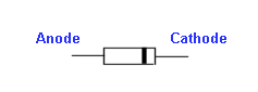 I'm taking the day off to do some long-overdue wood carving which has been on my to-do list since Christmas, but I'll be around if you have any questions.
|
|
#52
05-13-2008, 05:54 AM
|
|||
|
|||
|
Where is G106? I searched my CD-ROM and only found up to G104 in the G100's. Also for my CCRM there is no pin 25. It only goes up to 24. Were you talking about on the PCM?
I thought little pieces of metal moved in relays to open and close circuits?  I reread your post 3 times. 1st time I was completely lost. 2nd time I was sorta getting it. 3rd time .... ok I think I understand your electric-man talk. I've pulled my ECU/ECM from my car before and had to inspect it so I know what to look for as far as a bad board and your descriptions helped too.I have a soldering gun that came with some solder. I'm not sure what a "slim aluminium heat shunt tweezers" is, but I guess they'll probably have that at radioshack. I hate hate hate hate going to that place. I guess that tweezers resists solder so that you won't solder the tweezers with the circuit. lol - At least thats what I'd think it is. If the CCRM looks good and tests good if I take it apart..... can I use RTV to seal it??? or does the CCRM need ventilation?
__________________
1995 3.0L 3000GT NA FWD ATX - ProwlerGT on 3si.org 1995 3.8L Ford Windstar GL -------------------------------------------------------------------------- "I drive the newest 1995 Ford Windstar anywhere..... when its not broken."
|
|
#53
05-13-2008, 09:43 AM
|
|||
|
|||
|
Re: Attempts stall, Idle Pulses 600-800 rpms, horrible MPG
Oops, yep, the case grounding via pin 25 refers to the PCM, not CCRM. I haven't seen grounding details for the CCRM, but if there's electrical continuity from the mounting tab to the case then it'll be ok to add a separate ground wire. According to the diagram you've posted, the CCRM is grounded via pin 15, so it would be worth tracing that and ensuring that it's clean and secure at whichever ground point it leads to. The location of the ground points aren't shown on my diagram so I don't know where G106 is located.
Relays do indeed contain a spring-loaded moving contact, but PCB-mounted relays would typically be sealed units so that isn't something that one would normally disassemble. The heatshunt tweezers look like this, but I don't see them listed on the Radio Shack site, and yep, they're made from aluminium so they don't accidentally get soldered into circuit too. With a little ingenuity you could make something similar with a couple of offcuts of aluminium and a rubber band or similar to make them self-clamping, which would serve just fine for occasional use. Regarding sealing the unit - if you have to break a seal to open it then I'd reseal it, using a silicone-based sealant.
|
|
#54
05-13-2008, 10:38 AM
|
|||
|
|||
|
I present to you all.... the insides of the mighty CCRM:
        Aside from the expected debris, dirt, visiting MOSQUITO who met his match with electricity... I found the CCRM to look much better than I thought it would. The ONLY thing I saw questionable visibly was on the bottom of the board edge at the diodes where it looks like the whole edge of the board has bubbled. It may be along a trace on the board. I would think this was probably due to the major overheating in October. I don't like the CCRM's proximity to the upper radiator hose. In any case I'm gonna clean it and the connectors up good later today, ensure the ground/cont is good from CCRM to PCM, reinstall it, put the exhaust back together finally, and see what happens after I get the van to operating temp. I want to find out if that 15A fuse was an issue before I go clipping diodes on the CCRM. Selectron & anyone else - Interested in your opinion(s) of the bubbling or if this is just normal board construction.
__________________
1995 3.0L 3000GT NA FWD ATX - ProwlerGT on 3si.org 1995 3.8L Ford Windstar GL -------------------------------------------------------------------------- "I drive the newest 1995 Ford Windstar anywhere..... when its not broken."
|
|
#55
05-13-2008, 12:00 PM
|
|||
|
|||
|
Re: Attempts stall, Idle Pulses 600-800 rpms, horrible MPG
The bubbling effect on the tracks isn't uncommon, and it's mostly not a cause for concern. The old Sinclair computer circuit boards always had it, and just about every track inside a GEC TV would always be bubbled, straight out of the factory. If you rub the edge of your fingernail over it though you'll probably find that it's good and solid underneath. That can be confirmed by a few quick continuity checks from one end of a track to the other. If overheating had caused it then the green protective coating would be discoloured and broken, but from what I can see, it looks ok.
One thing which did catch my eye was the ceramic resistor on the edge of the board - that's the big white chunky-looking thing. Ceramic resistors are used when a considerable wattage is to be dissipated, and therefore they run hot, and that frequently leads to them drifting in value over time so it would be worth giving it a quick check. The resistance value is marked on the inner face - the side which is facing the relay - I can see the markings but can't read them. The markings are interpreted like so: 0.27 ohms would be marked 0R27 2.7 ohms would be marked 2R7 27 ohms would be marked 27R 270 ohms would be marked 270R 2.7 kilohms would be marked 2K7 27 kilohms would be marked 27K 270 kilohms would be marked 270K 2.7 megohms would be marked 2M7 ... so you're looking for a marking resembling one of those. Check the resistance one way and then reverse the leads and check again. Because it's in-circuit, it's unlikely you will read the exact value because there may be components in parallel with it, but for an in-circuit check, the value should be the marked value or less - never higher. If the measured value is higher then that indicates that it's faulty. I'm surprised at how dusty the unit is, so I hope the relays were well-sealed at the manufacturing stage.
|
|
#56
05-13-2008, 01:21 PM
|
|||
|
|||
|
Re: Attempts stall, Idle Pulses 600-800 rpms, horrible MPG
Ford kept the fan relays mounted separately from all the other relays in '99, when electrical things were changed around a bit. All relays became plug-in design that year. Two different sizes of relays for fan control were required. The larger one (gray in the photo below) was for "high speed". (I have lost one "high speed" relay in my 230 kmiles.) You can see an alligator clip and conductor lead that I've added. The lead is soldered to the high speed relay coil grounding conductor. During severe summer driving or when towing, the alligator clip is moved to a grounded bolt. This keeps the fan in high speed anytime the ignition key is "on".... hopefully helping the tranny and ac.
.  . Click on thumbnail to enlarge.
|
|
#57
05-13-2008, 02:06 PM
|
|||
|
|||
|
It was very hard to see, but here is what is written on it:
CPR 5 - 9 DALE 5w 62 Ω 5% C9423 Connections are at sector R6 on the board. Resistance is futile. Sorry. lolResistance is: 64.0 Ω on the nose and flipping the leads (testing at both metal prongs coming out of the ceramic) shows exactly the same thing. Do dis mean we have brokey CCRM? Omega symbol & Ohm's law: Ω & Ohm's Law
__________________
1995 3.0L 3000GT NA FWD ATX - ProwlerGT on 3si.org 1995 3.8L Ford Windstar GL -------------------------------------------------------------------------- "I drive the newest 1995 Ford Windstar anywhere..... when its not broken."
|
|
#58
05-13-2008, 02:17 PM
|
|||
|
|||
|
Re: Attempts stall, Idle Pulses 600-800 rpms, horrible MPG
Quote:
__________________
1995 3.0L 3000GT NA FWD ATX - ProwlerGT on 3si.org 1995 3.8L Ford Windstar GL -------------------------------------------------------------------------- "I drive the newest 1995 Ford Windstar anywhere..... when its not broken."
|
|
#59
05-13-2008, 02:21 PM
|
|||
|
|||
|
Re: Attempts stall, Idle Pulses 600-800 rpms, horrible MPG
I find it rather interesting that for the first time in my life I'm hearing/learning about these "ceramic resistors" and both are problems. The other day I replaced the ceramic dropping resistor for the cooling fans of course. Now I'm betting Selectron will say the ceramic resistor in the CCRM is bad based on his info that resistance shouldn't have been higher than 62. I guess I don't understand enough about electricity though yet to know why just 2 ohms higher (64) would be a problem..... but I await da grand masta electric-guy. TELL US O WISE ONE! ..... lol .... I need sleep.

__________________
1995 3.0L 3000GT NA FWD ATX - ProwlerGT on 3si.org 1995 3.8L Ford Windstar GL -------------------------------------------------------------------------- "I drive the newest 1995 Ford Windstar anywhere..... when its not broken."
|
|
#60
05-13-2008, 02:32 PM
|
|||
|
|||
|
Re: Attempts stall, Idle Pulses 600-800 rpms, horrible MPG
Quote:
__________________
1995 3.0L 3000GT NA FWD ATX - ProwlerGT on 3si.org 1995 3.8L Ford Windstar GL -------------------------------------------------------------------------- "I drive the newest 1995 Ford Windstar anywhere..... when its not broken."
|
|
 |
POST REPLY TO THIS THREAD |
 |
|
|


