|
|
| Search | Car Forums | Gallery | Articles | Helper | Air Dried Fresh Beef Dog Food | IgorSushko.com | Corporate |
|
|||||||
 |
 Show Printable Version | Show Printable Version |  Subscribe to this Thread
|
|
|
Thread Tools |
|
#1
 02-07-2014, 06:27 PM
|
|||
|
|||
|
2000 Windstart Alternator Smart Charge 14.7v @start, 12.5v after 30 minutes
This voltage decreasing appears to be a common symptom.
I've found a couple threads where they have described exactly what is going on with my van, but NO ONE has ever posted a solution! One clue may be the temperature sensor since one thread said the PCM determines temperature (of what, I don't know) in addition to battery voltage to determine voltage regulation level. The PCM feeds a pulse modulation signal to the alternator to regulate charge. The dash idiot light is part of the dash module and not controlled by a wire from the alternator (!) I wonder if anyone has installed a simple Open Loop alternator fixed at 14.7v and eliminated this monstrosity? Last edited by MrCreosote; 02-15-2014 at 01:34 PM. 
|
|
#2
02-07-2014, 07:03 PM
|
|||
|
|||
|
Re: 2000 Windstart Alternator Smart Chart 14.7v @start, 12.5v after 30 minutes
I just saw a youtube of a guy pushing the 3-wire connector on the RH end of the alternator to the Left and when he did, you could hear the engine rpm get dragged down from the alternator charging.
When he would let go of the connector, rpm would go up and he got a red instrument warning light. I'll have to try mine too. What is bothersome is that mine degrades like a Swiss watch! There is nothing unstable about this voltage decline. And the more the voltage has drooped, the more it drops when you turn on loads like blower and brake lights. I also wonder about temperature sensors. For one thing, I have to drive miles before the converter will lock up in winter. And I also question my not so good fuel economy with my only short trips usage. Still, someone must have solved the reducing voltage problem. Lots have reported it.
|
|
#3
02-08-2014, 10:46 AM
|
|||
|
|||
|
Re: 2000 Windstart Alternator Smart Chart 14.7v @start, 12.5v after 30 minutes
One thing to keep in mind is the battery.
A weak battery can cause the issues that you are seeing.....and shorten the life of the alternator.
__________________
Moderator for Ford Windstar room only Links to my pictures, intended as an aid, not a replacement for, a good repair manual. 1996 3.8L Windstar http://www.flickr.com/photos/4157486...092975/detail/ 2003 Toyota Sienna pictures (not much there yet) http://www.flickr.com/photos/4157486...781661/detail/
|
|
#4
02-08-2014, 11:28 AM
|
|||
|
|||
|
Re: 2000 Windstart Alternator Smart Chart 14.7v @start, 12.5v after 30 minutes
If its the battery I'd like to understand how that would be possible.
If the battery has no capacity, the alternator would maintain 14.5v continuously independent of what loads were turned on. If the battery has a shorted cell, the alternator would try to maintain 14.5v but would see excessively high current draw at that voltage. Being a 130 amp alternator I don't think a shorted cell would draw over 130 amps thereby drooping to 12.5 volts. Also, if there was such a shorted cell, the battery would not power the starter at 11 volts meaning it would barely start. And if shorted, it is unlikely that the battery heals itself overnight so that the first 10 minutes of operation, everything is normal at 14.7 volts. At 12.5v, either the PCM is not sensing the battery voltage, or the pulse modulation to the alternator is wrong, or the alternator is not responding properly to the PM. It is really a step backwards in robustness. In Olden Times, you had external voltage regulators and wiring. Then alternators became self contained units - even became One Wire! How we have the worst of both worlds, no only are we back to wiring but instead of a mere voltage regulator, it is now the ECU for the entire vehicle. With all the wiring problems Ford has had in the past, one would think they would avoid such a contraption or at least design harness connectors to sufficient durability.
|
|
#5
02-08-2014, 11:33 AM
|
|||
|
|||
|
Re: 2000 Windstart Alternator Smart Chart 14.7v @start, 12.5v after 30 minutes
Found this from Peter Cooper Car Repairs: http://www.petercoopercarrepairs.co....t_charging.htm
Really need to confirm if you remove the 3-pin connector from the alternator, "it reverts to a conventional alternator!" If that is indeed the case, bye bye smart charge. " Ford Focus alternator smart charging First things first, check the battery, not just condition, but correct type. A lead acid battery will not work properly with smart charge, it must be Silver Calcium! Easy to over look. Next, put a meter across the battery. Remember when you remove the smart charge 3 pin plug from the back of the alternator, it reverts to a conventional alternator! If you do not have about 13.8 volts, carry out basic charging system checks and suspect the alternator, its not a smart charge fault ! Correct charge voltage from the alternator, then its time to start on the smart charge system, and you will need a scope. First the system. Pin 1 = Alternator Feedback Pin 2 = Alternator Load Request Pin 3 = Reference Voltage Now, pin3, must MATCH battery voltage ! Its fed from a fuse in the CJB, and a high resistance on the fuse contacts causes a volt drop, and the smart charge drops out ! Next pin 1 & 2 need checking back to the PCM for resistance, isolation from ground and each other. If ok, its out with the scope. Pin 2 is the request from the PCM to the alternator. This will be a square wave pattern that will change with load request. So lights, screens etc on and monitor for a change in the pattern. (Obviously back probing with the plug connected) No change in the pattern means no request from the PCM, you should now suspect a PCM fault. Correct pattern and move on. Pin 1 is the feedback from the alternator and MUST remain a constant square wave pattern. If this pattern mirrors the one on pin 2, the smart charge part of the alternator is faulty, and a new unit is required. With these simple checks, you should always be able to diagnose a smart charge fault. Another point to add is, never, ever, jump start a Smart Charge vehicle with a flat battery. The system can produce up to 18 volts, which can fry major modules. The theory behind smart charge, is a battery will take a charges at its most efficient when it’s cold. Following start up, the PCM checks the Engine coolant temp, and intake air temp, and calculates a cold engine. It will then boost the battery charge, pulling it back as it calculates the under bonnet temp coming up. Its not there to compensate high demand as is the common misconception. The problem comes on a jump start, when the PCM sees a cold engine, and then a poor battery condition, and can then instantly zap out about 18 volts because its trying to recover the battery. Unfortunately this sudden surge can cook modules."
|
|
#6
02-10-2014, 09:57 AM
|
|||
|
|||
|
Re: 2000 Windstart Alternator Smart Chart 14.7v @start, 12.5v after 30 minutes
I'm very interested in this topic!
I had a similar experience a couple of years ago: After a battery failed, I started closely monitoring alternator voltage, and noticed that same behavior of a nice high voltage that slowly goes down as the van is driven. After two alternators and a number of swaps (at one point, I had perfected my technique to reliably swap Windstar alternators in under 15 minutes), I came to the conclusion that it was an annoying Windstar quirk that didn't have an obvious solution - so I let it be (but I keep a spare alternator in the garage, just in case). However, I did contact Duralast (the supplier for one of my alternators; the other came through a Ford dealer) and managed to find a technical support guy who had some hints about tracking down the behavior I was seeing. Text below is from Duralast technical support: ================================================== ============================= Hi Phil I am attaching a wiring schematic for your reference. I am also listing test steps that you have probably already done, but since it’s an intermittent issue, it doesn’t hurt to recheck everything. Based on multiple unit replacement and your extensive testing, I really suspect this is a PCM related issue. Vehicle Running, under heavy load, and after a good drive cycle, back. Positive terminal of battery to B+ post on back of alternator (circuit 36 at connector c133)= <.5v and >0v ( IE; less than .5v but greater than 0v ) Positive terminal of battery to og/lb (circuit 35 at connector c123) = <.5v and >0v Negative terminal of battery and housing of Alternator = <.5v and >0v The PCM controls can be monitored by scan tool and/or oscilloscope for most accurate information, for generic rough indication the two circuits can be monitored for frequency and duty cycle, however there are no fixed specs. Roughly 100-125 Hz and a duty cycle that increases with load To verify the part, it should be a DL3604-16-2 for a remanufactured part, or a DLG3604-16-2 for a new part Finally I would inspect the terminals very closely to make sure they are not spread out, as we do see lots of problems right at the connectors. ================================================== ==================================== Here's the diagram Duralast sent me: http://s892.photobucket.com/user/e39...tml?sort=3&o=0 Sadly, I'll admit that I didn't get a chance to monitoring the PCB signal he mentions. I have an oscilloscope, so I should probably try it. I hope this information helps spur some ideas...
__________________
2000 Windstar LX 3.8 1995 Contour GL 2.5 1986 Mustang GT 5.0 --> Sold, but missed on sunny days
|
|
#7
02-10-2014, 02:19 PM
|
|||
|
|||
|
Re: 2000 Windstart Alternator Smart Chart 14.7v @start, 12.5v after 30 minutes
Hi Phil,
I was hoping you would add your post - I saw it elsewhere and it was the only other technical post on the subject. I'm glad the schematic works here (I think it no longer worked where I found it elsewhere.) The UK info was intriguing about "alternators works like a normal one with the 3-wire connector disconnected." I did this and saw voltage increase from 13.2 to 14.0 at the battery. So I figured I'd just drive the van w/o the connector. NOT! Disconnected, the alternator will not "turn on" when engine is started. You have to "jump start" the alternator by momentarily connected the 3-wire connector! Now checking battery voltage at the clamps and cigarette lighter and found a 0.3 to 0.4v drop. That is bad. Further with big loads, the battery dropped about 0.1v while at the cigarette lighter it dropped about 0.3v so there is some serious resistance somewhere in the circuit. I read in some other thread to replace the entire positive battery cable assembly. From the schematic, this might not be a bad idea since I could not measure anything >0.1v difference between the NEG post and alternator case or ground straps on the from fascia panel. The drops might all be related to the POS cable and its fusable links. Anyhow, I'm not very happy because I am just killing this Interstate battery that is good but old! Did you ever really solve your problem? Around town you could simply leave everything hooked up but if you have to go on a long drive, unhook the 3-wire connector! (hahahaaaa) Your 15 min "racing alternator change" I assume the trick is the serpentine belt? Can you share how you handle that? Thanks Tom
|
|
#8
02-10-2014, 04:59 PM
|
|||
|
|||
|
Re: 2000 Windstart Alternator Smart Chart 14.7v @start, 12.5v after 30 minutes
My Windstar is in daily use with this annoying quirk in place. Almost all the time, I don't notice a real problem. That said, it seems that batteries in the van don't last quite as long as I think they should. A few times, we've accidentally left a door open or something like that - and starting the van ended up requiring a jump (I may also have a sticky door switch; a project for another day).
Regarding the schematic - and other pictures I've shared earlier: The Webshots shutdown trashed the albums I've used to document Windstar projects. I moved many of the pictures to another site, but haven't had a chance to deal with all of them. Regarding voltage drops: Yeah, a cable-related voltage drop of 0.3V (as measured with a quality digital meter) would be of concern. I have seen corrosion build up *inside the cable insulation* near a battery terminal. I find that a light coating of oil or dielectric grease on battery terminal hardware prevents most corrosion. My Windstar terminals are original and corrosion-free by doing this. My quick alternator change method: I bought a Harbor Freight "serpentine belt tool" and cut about 6-8" (IIRC) off the long handle so it conveniently fit in the space I had available. I taped the appropriately-sized crow's-foot end in place (so it can't fall off). I learned that - once the belt is loosened with the tool - to loop it off of the alternator pulley and use a piece of tie wire to hold it in place (so the belt stays in the correct spot on the other pulleys). The alternator comes right out and the new one goes right in. Then I use the belt tool to loosen the belt and quickly get it back on the alternator - again, without disturbing the belt's location on other pulleys. If I goof, it takes longer to ensure the belt is in the right spot than to replace the alternator itself. If done correctly, the whole job can be done without going under the van. My theory on this whole situation: Ford developed the "smart charge" system to help fuel economy (less accessory load) and avoid overcharging the battery (which is one problem with a high-voltage-all-the-time approach). Unfortunately, it appears they created a system that can easily fail silently (i.e., no alternator warning light appears) and can cause strange behavior. In a world with more spare time, I'd like to set it up so I can monitor the PCM-to-alternator signal while driving, and understand exactly how the PCM decides how to vary that signal.
__________________
2000 Windstar LX 3.8 1995 Contour GL 2.5 1986 Mustang GT 5.0 --> Sold, but missed on sunny days
|
|
#9
02-10-2014, 05:41 PM
|
|||
|
|||
|
Re: 2000 Windstart Alternator Smart Chart 14.7v @start, 12.5v after 30 minutes
I read a thread where they said the PCM uses Temperature as part of the charging calculation. I believe they mention IAT (Inlet Air Temp) and Water Temp.
I was also thinking maybe I had a temp sensor that was reading low requiring more time spent cold open loop and wasting gas. I need to go over your schematic. I think it is different from the UK information where I believe they say there are 3 wires that go to the PCM. Weather here is either frigid cold or lots of snow. Difficult to work in. What is interesting is that with the 3-wire off, I get 13.9 to 14.0v from the battery terminals which is 0.2 to 0.4v low. __________________________________________________ _ Interesting corrosion failure in a 72 Datsun 510. Battery seemed like had no capacity and would not crank car. What happened was that a weird layer of oxide formed between the post and the clamp. You could clean the post with a wire post clean and NOT remove this layer!!!! It had to be chipped off. It was like chipping rust off. It looked like lead too which really made it difficult if not impossible to detect visually. ___________________________ I wonder what a new POS cable assembly or alternator harness costs?
|
|
#10
02-10-2014, 06:26 PM
|
|||
|
|||
|
Re: 2000 Windstart Alternator Smart Chart 14.7v @start, 12.5v after 30 minutes
Quote:
__________________
2000 Windstar LX 3.8
|
|
#11
02-10-2014, 08:08 PM
|
|||
|
|||
|
Re: 2000 Windstart Alternator Smart Chart 14.7v @start, 12.5v after 30 minutes
Interesting PDF file of SCS (Smart Charge System) alternator voltage regulator.
Shows the function of the PWM (Pulse Width Modulation) and how it effects charging voltage. http://www.onsemi.com/pub_link/Collateral/CS3341-D.PDF
|
|
#12
02-10-2014, 08:20 PM
|
|||
|
|||
|
Re: 2000 Windstart Alternator Smart Chart 14.7v @start, 12.5v after 30 minutes
Tom -
Very interesting. The translation of a sawtooth pattern's voltage level to an alternator field duty cycle should be pretty easy to see with an oscilloscope. Thanks for sharing!
__________________
2000 Windstar LX 3.8 1995 Contour GL 2.5 1986 Mustang GT 5.0 --> Sold, but missed on sunny days
|
|
#13
02-10-2014, 08:31 PM
|
|||
|
|||
|
Re: 2000 Windstart Alternator Smart Chart 14.7v @start, 12.5v after 30 minutes
An article by Hobbs in Motor Magazine going through all the various smart charging systems. These are GM but the diversity of design is mind boggling:
Are You Smarter Than a Smart Charging System? By Dave Hobbs | April 2010 Download PDF No matter how complex smart charging systems appear at first glance, it still comes down to a battery, an alternator and some modules monitoring and controlling voltage regulation. Were sure youve got the smarts to handle that. Nearly every time I look at an alternator it conjures up fond memories of growing up in a family-owned auto electric shop. In the 1980s, Chrysler pioneered voltage regulation with an engine control computer on its first EFI systems. Chrysler still uses a similar method of voltage regulation today. Quite a few years later, Ford followed with a powertrain control module (PCM) connection to the alternator. Not to be outdone, GM and others joined the ranks of OEMs using some form of strategy to tie engine management and voltage regulation together. Although the image of a full field test with a pocket screwdriver making sparks in the D hole of a Delcotron is outdated, simple tests for outsmarting todays so-called smart charging systems are out there for the tech whos willing to learn what makes these latest systems tick. To keep this smart charging system visit manageable, well focus on GM passenger cars and light-duty trucks. Before we venture too far out into the deep water on the latest charging systems, lets do a bit of review. Not a bad idea considering that many techs reading this have never seen the inside of an alternator, as the art of rebuilding has becomes a thing of the past for most shops. The primary missions for any alternator are to maintain a charge on the battery and keep up with the vehicles electrical accessory demand. To accomplish these tasks, a rotating electromagnetic field called a rotor induces an electrical charge into three windings that are 120° out-of-phase. These windings (the stator) create alternating current that in turn is rectified into direct current by a set of diodes in the back of the alternator. Pretty basic stuff, right? The job of the voltage regulator has always been to control the amount of electrical energy (field current) in the rotor via electrical power supplied to the brushes on the rotors slip rings. The greater the current supplied to the slip rings, the more voltage (and current) the alternator puts out. As electrical loads such as the headlights, blower motor or rear defogger are added, the regulator senses a reduced voltage and applies more power to the rotor, allowing the alternator to keep up with the electrical demand. When the regulator fails, it usually causes one of two problems: Either the rotor does not receive power and there is no charging output, or the regulator gives full power to the rotor and the alternator puts out too much voltage, boiling the battery dry and burning out light bulb filaments. Then and Now To understand where we are now, its important to know where weve been. Historically speaking, the description just given is pretty much the way its been since voltage regulators moved off the firewall and into the back of the alternator in the 1970s. These fundamentals have changed very little until the last five years for GM. One change with voltage regulation did take place in the mid-80s. It was found that as engines became smaller and developed less torque, the sudden reaction to an increased load on the accessory drive belt sometimes caused a rough idle/vibration, or even engine stalling. Power steering pressure switches and a/c compressor request/control circuits all helped with idle quality, but there was nothing to tip off the engine management computer that an increased load was occurring from the alternators varying field current. Every tech has heard an engine bog down when the alternators output ramped up in response to increased electrical load. Faradays law of induction tells us why this occurs, but that doesnt help the PCM with engine management. Engineers came up with the solution and the four-terminal voltage regulator was born in the late 80s. This change caused confusion that has lasted until the pres*ent day, due to the variations of systems using one or more of those four-terminal regulators. The letters P, L, F and S were stamped on these regulators to identify the terminals. Unlike SI (series integral) alternators with the older two-wire regulators, the newer design CS series alternators eliminated unmanaged load dump (fast field ramp-up) that caused the rough idle and stalling issues when the electrical loads were suddenly turned on. These CS series machines gradually ramped up their fields with a 400Hz pulse-width modulated (PWM) output from the regulator to the rotors brushes. No more stalling and no more vibration when the accessories were all turned on. Of the four terminals, the P terminal was seldom used with the exception of some diesel applications. The P stands for Phase and is the output of one leg of the three stator windings, giving a tach signal to a diesel engine controller. The L stands for Lamp and goes exactly to where you might think it wouldto the charge lamp indicator. The F stands for Field and provides a square wave to the PCM, allowing it to know the field strength (torque demand) of the alternator. On some models the third terminal is marked I for Ignition and acts as a backup for regulator turn-on voltage should the bulb in the cluster fail to provide voltage to the L terminal. The S stands for Sense and is connected to a location in the wiring harness where accessory current draw is high, such as a fusible link at the starter or a bussed electrical center. While many vehicles used only one wire (the L terminal), there were quite a few that populated the regulators connector with two or three circuits, and this led to a major source of confusion that still exists today! Which of these circuits is really needed when performing simple diagnostics? The answer is, in almost all cases, the L terminal. Test Light or Lab Scope? Thats enough theory; now on to something practical! If youre working on a GM product, whether its a 1989 or 2004 model, you can determine with a simple test whether a charge problem is due to a defective alternator or a problem with one of those four wires going to the regulator. With a voltmeter connected to the battery, simply disconnect the voltage regulator, then start the engine. Next, connect the alligator clip of a conventional test light (not the newer LED style) to a nearby source of battery positive. Finally, touch the test light probe to the L terminal of the voltage regulator, as shown in the photo at left. Your test light will do the job of the clusters charge light. When the alternator is not charging, that L terminal will be grounded (the test light will glow), and when it is charging, the light will go off. The reduced voltage provided by the test light will provide the necessary excitation signal for the regulator to come to life. Note: If the regulator connector is in a difficult location, use a short jumper lead to do the job. If the alternator sings and your voltmeter jumps up to show charging voltage, the alternator is likely good and you must move your focus to the wiring leading to the regulator connection. If it doesnt start charging, the alternator is definitely bad and its time to sell a new or reman unit to the customer. I said the alternator is likely good if you touched the test light probe to the L terminal and it began to charge. I left some wiggle room here because not all four-wire GM voltage regulators are created equal. Some aftermarket alternator rebuilders try a little too hard to reduce their part numbers to a leaner inventory, creating alternators that charge but may not charge properly. Without going too deep into that, Ill just say that GM had good reasons to use one, two, three or all four of those regulator terminals, so the one-size-fits-all reman part may give you grief. During the late 90s, we started seeing the L terminal on the CS series four-wire regulators connected to the PCM, as well as the F terminal. This led many techs to assume that the PCM controlled the field current, as it does with Chrysler. It does not. It does provide a signal to the L terminal for exciting the regulator and does receive a ground on that circuit when the engine is stopped or the alternator has failed, just as before when the circuit was connected to the charge lamp in the cluster. The difference now is this PCM connection to the regulators L terminal can inhibit sending the excitation signal to that circuit, which would prevent the alternator from charging. Why would it do that? It does so to delay the introduction of field current into the rotor during engine start-up. Remember Faradays law? Improved starts occur when an engine doesnt have to deal with an alternator load on its drive belt. After the engine starts, the PCM uses the circuit leading to the regulators L terminal as an input. If it sees a ground on that circuit, such as when the alternator senses a problem internally, the PCM then sends a serial bus message to the cluster requesting the charging indicator to come on. Most scan tools can read the PCM PIDs for the L terminal status and the percent of duty cycle the PCM sees coming from the F terminal. You can also scope the F and L terminals to watch the regulator ground the voltage pulled up by the PCM on the L terminal and observe the 400Hz signal on the F terminal displaying the duty cycle that the rotor winding is receiving (see Fig. 1 on page 42). Now Were Getting Complicated If the CS series of GM alternators werent smart enough for you, we have the latest systems called Regulated Voltage Control (RVC) showing up on the scene in the mid 2000s. Why a new system? Batteries are sensitive to temperature. The lower the batterys temperature, the lower its chemical and electrical reactivity. This means the battery puts out less voltage in cold temperatures and needs more voltage to charge. Conversely, a battery puts out more voltage and needs less voltage from the alternator in warm weather. While Chrysler did indeed use an external temperature sensor to sense battery temperature for its PCM-controlled voltage regulation, GM always used a thermistor built into the voltage regulator to sense underhood temperatures for charge rate compensation. These days, with battery locations spread out everywhere from the engine compartment to the trunk to the back seat, a better way of detecting and compensating for battery temperature had to be developed to replace the temperature sensing that traditionally occurred within the voltage regulator. Keeping batteries charged with just the right voltage and maintaining greater than 80% state of charge (SOC) helps them last longer. Shedding Some of the Load Helping the battery achieve the SOC goal has been the job of another smart charge feature called load shedding that has actually been around for well over a decade. The alternators pulley turns slower when the engine is idling, causing less output. When idling with a heavy electrical accessory load applied, the alternator may not be able to keep up, and the voltage to the battery drops below 12 volts. If this continues for very long, the battery can drop below the desired 80% SOC. Load shedding has been a function of the body control module (BCM) in both the older CS series alternators (four-terminal regulator) and the newer Regulated Voltage Control (two-terminal regulator) systems. Load shedding basically is a function of the BCM or another module on the serial bus (Power Mode Master) watching battery voltage and doing something about it if it gets too low. The process involves first requesting the PCM to boost idle speed to raise the alternators output enough to keep up with the heavy accessory demand and still trickle a charge into the battery. If the first idle boost doesnt do the trick, subsequent idle boosts are commanded before a more aggressive action is enabledreducing power to certain power-consuming accessories, such as the rear window defogger grid. Regulated Voltage Control Explained Regulated Voltage Control uses information from the battery current sensor, calculated battery temperature and system voltage to determine what the perfect voltage to supply the battery with is. In addition to nurturing the battery into longer life by maintaining proper state of charge, RVC allows the charging voltage to drop below the 13.8 to 14.8 volts to which were all accustomed. If the battery can maintain an 80% SOC with 13 volts at a particular temperature, why would we want to charge it at 14.8 volts? Higher voltage comes at a price of increased drive belt load. Every bit counts with todays fuel economy goals. Additionally, light bulb life is increased with a slightly lower charge voltage. Depending on the model and year, the newer GM RVC charging systems may include up to nine different charging rates strategies, among them: Battery Sulfation Mode. No sense hammering a battery that has given up the ghost! Start-Up Mode. Gets the battery back up to greater than an 80% SOC quicker. Fuel Economy Mode. Alternators that put out less voltage help engines use less fuel. Headlamp Mode. Okay, its time for a little more voltage now that the lights are on. Referring to the RVC graph in Fig. 2 on page 44, you can see how much thought has gone into tailoring the alternators charge output to suit various scenarios. An interesting sidebar note would be the ramp-up in field current that the RVC systems sometimes introduce on deceleration. When youre cruising in Fuel Economy Mode (lower charge voltage), you can charge harder during a brief period of deceleration without sacrificing fuel economy or overcharging the battery. In fact, when theres a greater alternator load on the engine during deceleration, that load contributes to engine brakingsomething thats good for brake pad life as well. Think of this as a mild form of what hybrid vehicles do with regenerative braking. Speaking of hybrid vehicles, DC-to-DC converters (high voltage in, conventional 14 volts out) come online whenever hybrid systems are powered up. This may occur with the key on and the engine off. The DC-to-DC converter receives serial bus messages from a BCM or PCM on the vehicle responsible for the equivalent of RVC functions. This allows a hybrid vehicles DC-to-DC converter to tailor a perfect charge rate into the vehicles 12-volt battery. RVC Operation & Diagnostics To be clear, GMs RVC systems use alternators with field currents that truly are controlled by logic external to the alternator. Youll see two things right off the bat on RVC vehicles tipping you to the presence of this latest technology: First, youll see a two-wire voltage regulator connection instead of the familiar four-wire connection. Second, youll notice a funny-looking sensor or module wrapped around either the negative or positive battery cable. It may remind you of an inductive current probe, because thats what it is. There are two types of these systemsstand-alone RVC (SARVC) and RVC. The former was used for a few years (mid-2000s) on light-duty trucks and SUVs. The current sensor in the SARVC system is built into a full-fledged electronic module complete with a Class 2 serial bus circuit to receive and transmit information. You probably wont find the data PIDs for this system in the PCM. The SARVC module is also known as a generator battery control module (GBCM) and is located within a list of body modules on the scan tool. Not all aftermarket scan tools can read this module, but they will display PIDs like Battery Voltage, Battery State of Charge, Regulated Voltage Control Current and Generator L Terminal Signal as a percentage. The RVC systems use a Hall effect type current sensor that sends a PWM signal at 128Hz to the BCM. This sensor stays powered up long after the ignition switch is turned off. The reason is that this sensor also reports to the BCM any news of excessive parasitic current draw. This is also a scan tool PIDnice to know when diagnosing a battery rundown problem on a RVC-equipped GM vehicle. And speaking of PIDs, since the BCM is the module in charge of logic for this system, youll find up to 20 PIDs under a heading titled Charging Info when searching for charging system PIDs within the BCM. Although the BCM is the brains for the non-stand-alone RVC system, its the PCM that actually carries out the commands to control the L terminal with a PWM output to control the alternators charge rate. To find output PIDs, go into the Powertrain section on your scan tool. You may encounter output PIDs in the section of the PCM titled Electrical/Theft. As with earlier non-RVC, four-terminal CS series alternators, the L terminal can be commanded on and off by going into the PCM and selecting output control. On RVC vehicles, youll see the charge voltage fluctuate while driving or even while running the engine in the bay. The changes will be subtle, as the rate of change varies from 10 to 20mV per minute. Charging rates as high as 15 volts are observable on some vehicles, depending on current demand and battery SOC, along with values as low as 12.9 volts. The PWM signal from the PCM to the L terminal on these two-wire regulators varies from 10% to 90%, with the latter being the higher voltage command (15.5 volts). If this circuit goes open, the default charge rate from the alternator is 13.8 volts. One way to outsmart the smart charging system is to disconnect the current sensor or SARVC module. On some systems youll see 15.5 volts with the engine running and a light electrical load applied. This should tell you if youre dealing with a good, old-fashioned alternator problem or a vehicle wiring or module problem. Naturally, DTCs will be set that will have to be cleared. Dont forget to look in the Body Controls section of your scan tool when clearing codes, in addition to the PCM. But no matter how complex these systems seem, it all really comes down to a battery, an alternator and some modules monitoring and controlling voltage regulation. By knowing how these new systems work, you can keep outsmarting the latest smart charging systems that show up in your bays!
|
|
#14
02-11-2014, 08:56 AM
|
|||
|
|||
|
Re: 2000 Windstart Alternator Smart Chart 14.7v @start, 12.5v after 30 minutes
Ford Smart Charge System overview and some detailed functionality explained:
http://askpete-hella.com/2011/04/07/...ol-units-work/ So this information is not lost: How do external alternator control units work?  As vehicle electric systems become more and more complex, simple alternator regulation is usually no longer sufficient. For this reason, some vehicle manufacturers (e.g. Ford, BMW, Mazda, Peugeot) have integrated so-called intelligent alternator control units into their charging systems. As vehicle electric systems become more and more complex, simple alternator regulation is usually no longer sufficient. For this reason, some vehicle manufacturers (e.g. Ford, BMW, Mazda, Peugeot) have integrated so-called intelligent alternator control units into their charging systems.While in a conventional alternator, the built-in control unit determines the alternator rated voltage, this task is taken over by the engine control unit with these new systems. The function is explained below using a system built into a Ford vehicle as an example. Ford Smart Charge alternator control The alternator built into this system does not look significantly different from conventional alternators. In this case, there is also a voltage controller on the rear of the alternator. This controller is connected to the engine control unit (PCM) by means of two signal cables. Pulse-width modulated signals are transmitted between the alternator and PCM via these cables for communication purposes. On the basis of this information, the PCM monitors and controls the charge voltage. The function of the charge control lamp in the instrument cluster is controlled by the PCM. For the function test, the control lamp is switched on after the ignition has been switched on, and switched off again after the engine has been started provided the system function is fault-free.  1. Charge voltage regulation and calculation of battery temperature Since warm batteries are more efficiently charged with low voltage and cold batteries with higher voltage, the charge voltage is adapted by the PCM depending on the battery temperature. Reference parameters for calculation of the battery temperature are the intake air and the coolant temperature. The battery charging current is optimised through permanent calculation of the battery temperature and adjustment of the alternator output voltage. 2. Alternator switch-off when engine starts When the engine is started, the alternator is deactivated by the PCM to reduce the engine drag torque. The alternator is only switched to the required value electronically by the PCM after the engine has been started up. 3. Increasing idling speed at low voltage and high electrical load When the battery charge is very low or the electrical load in idling is very high, the PCM can gradually increase the speed up to 150 rpm in order to increase alternator performance. 4. Advance notification function for alternator load The PCM receives information about imminent electrical load from the alternator via the signal cable, and can thus compensate the expected alternator torque by increased idling speed. The PCM can guarantee greater idling stability on the basis of this information. By monitoring the vehicle electric system voltage, the PCM can change the charge current by changing the pulse-width modulated signal to the alternator. 5. Activating or deactivating electrical consumers By linking the PCM with the central electronics module, the following consumers are activated or deactivated in the event of over-voltage or under-voltage depending on battery voltage:
Damage caused by excessive vehicle battery charge is reduced by activating individual consumers, and at the same time the charge voltage is kept within the specification. Switching the consumers on increases the engine load and thus serves to support the control unit at the same time in the warm-up phase. If the battery voltage falls below the limit value, the consumers are deactivated again to prevent excessive discharging of the battery. 6. Diagnosis and limp-home function The diagnosis possibility of the Smart Charge system is implemented through the engine control unit (PCM). System faults are stored in the engine control unit and can be read out using a diagnostic unit. After the ignition has been switched on, the system carries out a self-test. If a fault is detected in the Smart Charge system during the self-test, the charge control lamp is not switched off. The alternator is operated at a fixed charge voltage of 13.5 V if voltage regulation is not possible due to the fault. This enables the alternator to generate enough current to supply the vehicle systems. During driving, the charge control lamp is only switched on if the PCM detects the following faults:
PCM: Engine control unit GEM: Control unit for the central electronics a: Communication cable for consumer control (CAN) b: Communication cable for charge control lamp (CAN) c: Monitoring signal alternator function d: Control signal alternator cable 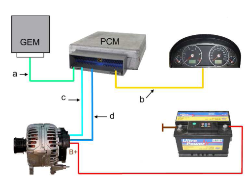
|
|
#15
02-11-2014, 09:02 AM
|
|||
|
|||
|
Re: 2000 Windstart Alternator Smart Chart 14.7v @start, 12.5v after 30 minutes
An interesting forum thread with Scope Pictures of person trying to solve same problem. Others also say have same problem.
What is interesting is that in this thread, they say the Silver Calcium battery should be charged at 13.8v instead of the 14.4-14.8 that I found in another thread (posted in this thread.) They question the 13.9v regulation with the 3-wire disconnected. One would think an old school "over 14v" regulation. Which points back to the use of a S-C battery. (You have to watch what country these threads come from since Ford USA is basically different from the rest of the world.) Again, NO SOLUTION FOUND! NOTE: There is virtually no mention of replacing wiring harnesses. And absolutely no mention of replacing the ECM. What is interesting is that on RockAuto, the 2000 Windstar ECM is about $110 exchanged. Funny. That is almost the price of an external regulator. The Body Control Module is something like $40. Funny Again: the battery cables cost more than the Computers! http://www.fordownersclub.com/forums...-smart-charge/
|
|
|
POST REPLY TO THIS THREAD |
 |
|
|


