The body is being polished and detailed- should be finished soon. That means it's time for the electrical system.
I've never bothered to light a car model before. It's one of those things (like opening hinged doors) that I think more often ruins a model instead of making it better. It can be very challenging to make headlights work on a car, and at the same time make them look
good.
But that has changed a bit recently with the proliferation of LED lighting on cars. In the last 10 years, a lot of different manufacturers are now building LED accents into their cars. Ferrari, Audi, Honda, Toyota, Range Rover, and now many others now have LEDs. There are two big advantages to LED accents for car modelers.
1- LEDs are realatively easy to work with. They are small, bright, easy to power, very long lasting, and don't put out much heat. Nearly all 1/24 cars have enough space in them for a couple of LEDs and a power source.
2- Lighting for accent is much easier to do than lighting for illumination. Supplemental style lighting isn't designed to light up the roadway ahead for the driver. Rather, it serves simply to make the car more visible and recognisable- for obvious safety benefits, but also to make the car look more sporty/modern/cool/expensive/etc. But as these lights are not nearly so bright as a projection light like a headlight, it is much easier to build them into a model (and to photograph them, for that matter).
BMW might be to blame for starting this trend in LED style lighting. The E39 5 series in 2000 was the first car to appear with illuminated headlight rings- dubbed "angel eyes". They quickly became extremely popular, and BMW soon adopted them as a brand image feature- nearly every BMW made for the past 10+ years has them. Of course, many other manufacturers have since followed. The E36 was never made with angel eyes (production of the E36 had just ended and the E46 was starting), but it has been a popular retrofit on all BMWs of this era.
The electrical system for this build requires three elements: lights, a power source, and an on/off switch. The choice for lights is simple- 3mm superbright clear LEDs seemed the obvious choice. I use these for
supplemental lighting in my machine shop. I get them from
Tayda or
Futurlec.
For a power source, I decided that I wanted on board power- so I could put the lights on and leave the model entirely freestanding. Again, there is plenty of unused interior space on this build- the boot and engine areas are empty. I could easily fit a blocky 9V in the trunk, and get a decade or more use out of it. But a 9V would require a voltage regulator or at least a fat resistor to step the power down to a useful level- and these generate heat. A couple of AA or AAA batteries would be a more practical option. But the option I settled on was a coin battery. This meant that I would have to build a battery holder as well, but that's a pretty simple matter.
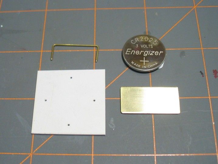
The base of the holder is just a piece of thick styrene card. The electrical contacts are brass strip and rod.
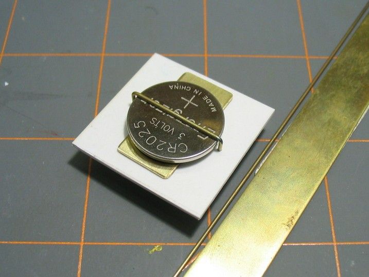
Solder a couple of wires in place and done.
The on/off switch proved to be more complicated. I wanted something as small and discrete as possible, so that it would not visually effect the finished model. But searching through options, I could find nothing small enough that I was happy with. There were also a few other factors. While I definitely wanted on board power (for model shows and the like), I also realised that it would be nice to add the ability for remote swtiching- say a wired switch with which I could control the lighting without having to disturb the model (think displaying it on a shelf). Ideally, it would also be great to be able to run the lighting off of an external power source also- so as not to run down the on board battery.
Fortunately, this tall wish list suggested a very practical solution. I realised that instead of bothering with a switch, I could connect the LEDs and battery to a header- and then select the mode of operation I wanted with a jumper. This gives the ability to run either on board power, onboard power with remote switching, or remote power and switching. Even better, using a jumper as a switch is the smallest, simplest, and least visually impactful solution I could imagine.
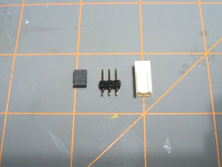
The header is the three prong thing in the center. On the left is the jumper (which connects two pins), and on the right is a connector. As ever, the grid is 1" for scale- these are fairly small components.
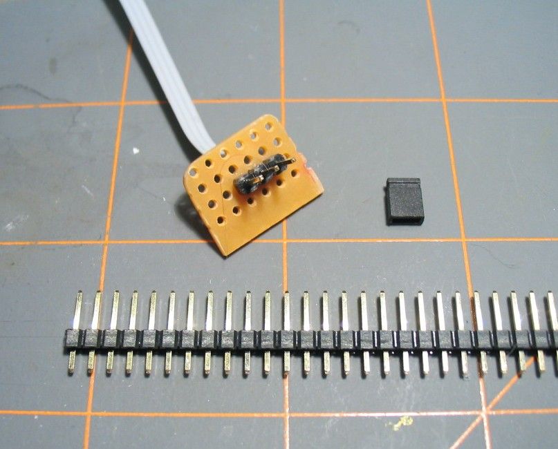
Headers come in long strips. You clip off as many as you need, and then solder them onto a circuit board. In this case, three pins will give me all the capabilities I want.
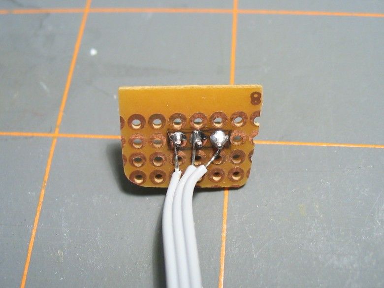
Not the prettiest soldering job, but fully functional.
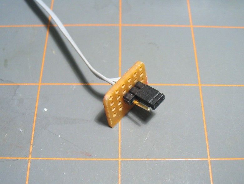
Putting the jumper on the right two pins will close the circuit and turn on the lights. If the jumper is removed (or on the other two pins), the lights are off and the battery is not being discharged.
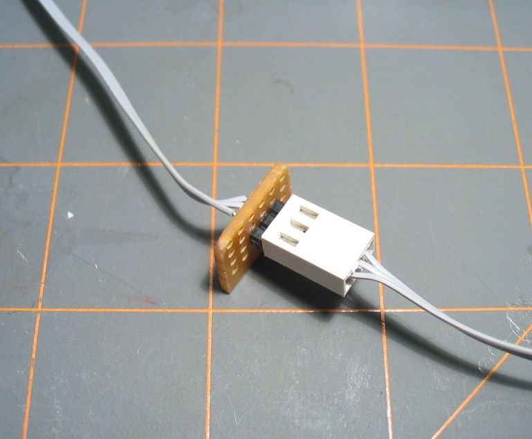
Or I can remove the jumper and substitute a connector- which will give me the ability for remote power and/or switching.
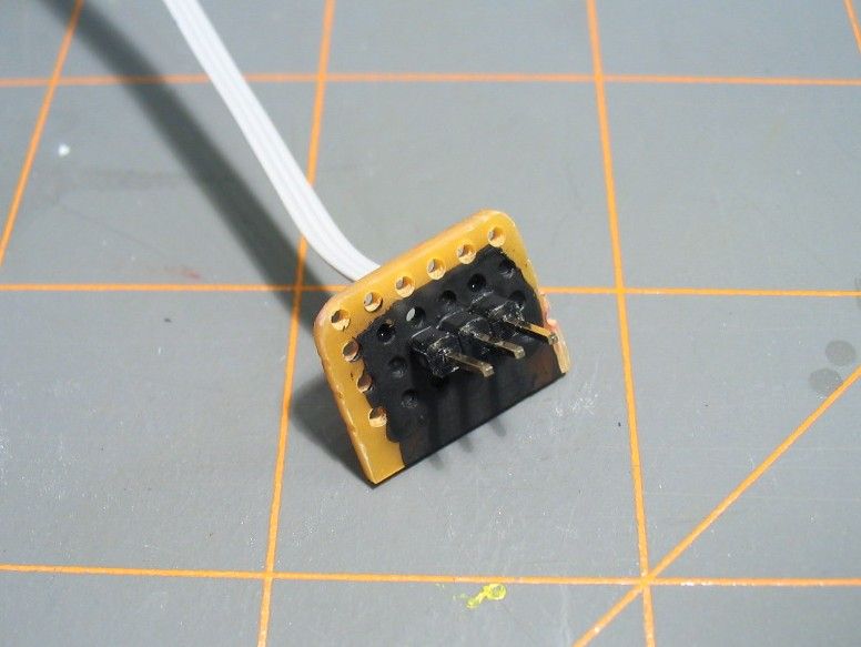
Painted black and ready for installation. It just needs to be glued in place in a suitable location.
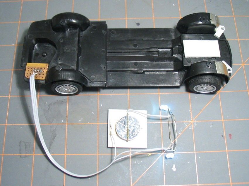
So, where to put all this? As the header is the only externally accessible component of the electrical system, I wanted to put it somewhere out of the way- a rear corner seemed like a good choice.
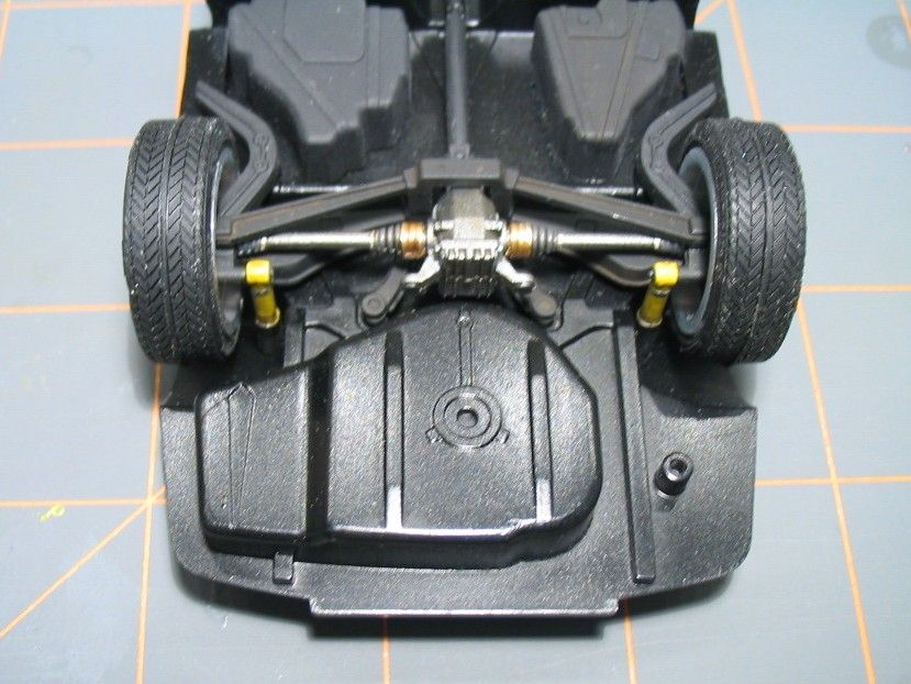
The muffler will go on the right side here- but the left side is a good option. Ironically, the rectangular area next to the spare wheel is where the battery is on the full size car!

So simply drill and file a suitably sized and shaped hole here.
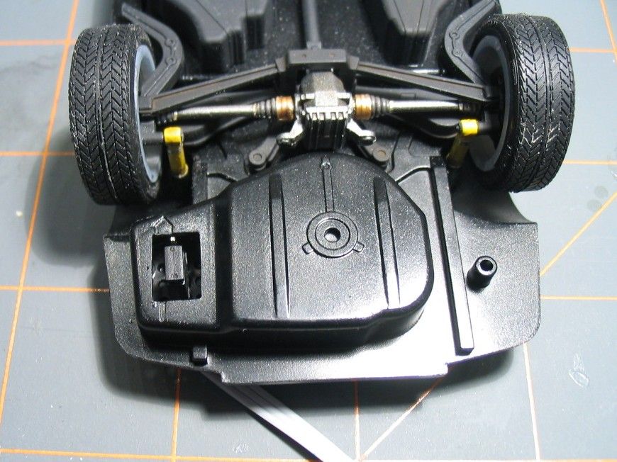
Glued in place. Here, the jumper is in the "off" position. It isn't necessary to have it in this position for the lights to be off- but it makes a great place to store the jumper.
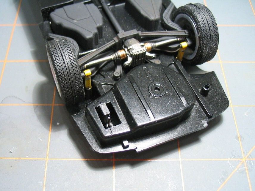
And here is the jumper in the "on" position. With the body on the chassis, this installation is next to invisible.
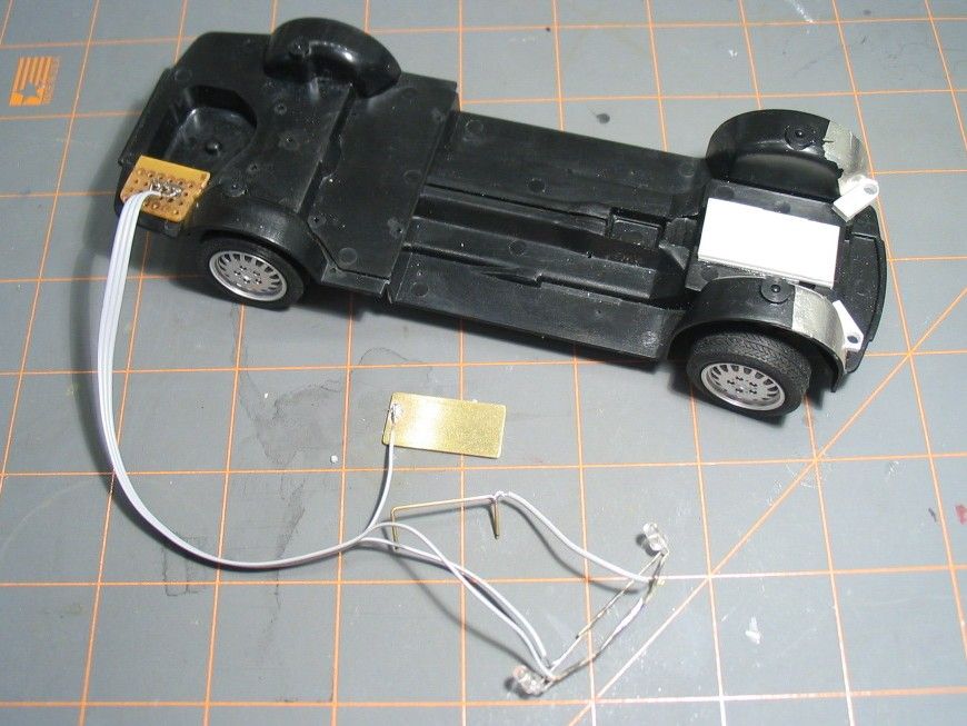
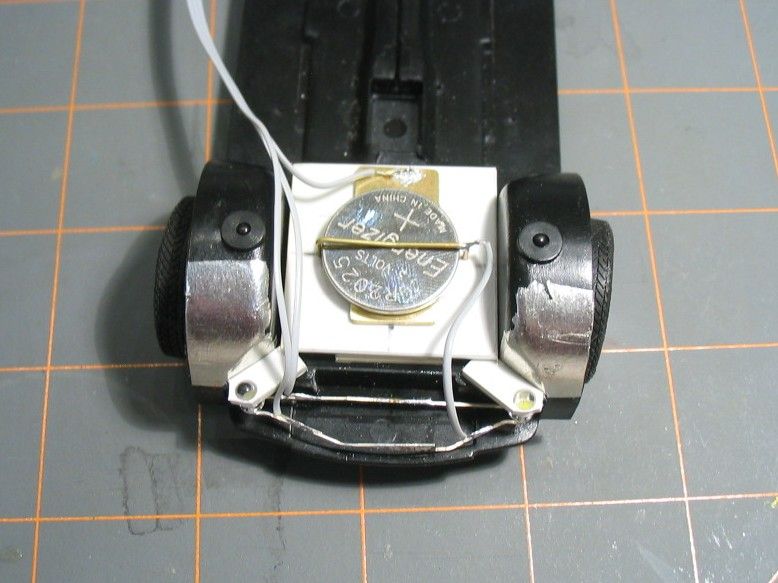
Here are the other components soldered together. The 'legs' of the LEDs are bent to the side and soldered together (make sure they are connected properly, or one or both will not work!!!). The positive and negative connectors for the battery are also soldered in place.
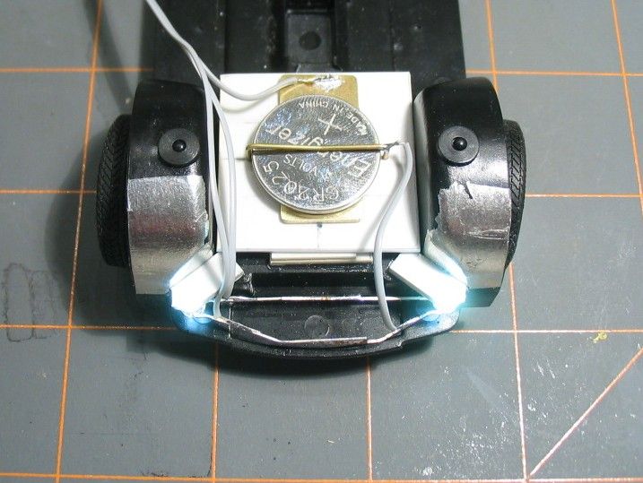
With the battery holder assembled and the jumper in the proper position, the LEDs light up! The positive connector has its ends placed through the styrene card and then bent outwards to hold them in place. The negative connector is simply stuck to the styrene with double sided tape. A downward bend in the brass rod keeps the battery in place.
All in place.
All on!
More to come.