...and here
is the next update.
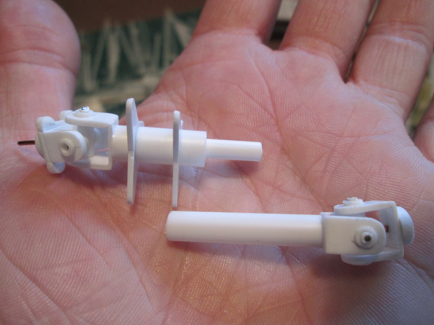
Starting point for each of the universal joints was two 1/4" lengths of 3/8" box-section; pilot holes were drilled through two sides, then the third side was removed to create the C-section. The inside faces were reinforced with two lengths of 0.5mm strip. The pilot holes were taken out to 1/8", then each half of the joint was pushed onto a length of rod (to make it easier to hold) whilst the ends were rounded-off with file and emery cloth.
From here, each of the joint sections was modified to suit it's position on the shaft. The innermost ends (onto the gearbox) were given a slightly thicker base and some half-round detailing to create the gearbox output flanges, plus a central spigot to help locate them in place. The other half was given a two-stage spigot which would pass through the first of the two spider flanges. The outermost joint was designed to locate into the hub in the trailing arm, whilst the other end was attached to the driveshaft itself.
To allow for a little movement as the suspension was articulated, the outer end of the driveshaft is able to telescope into the inside of the donut joint - an internal tube provides support.
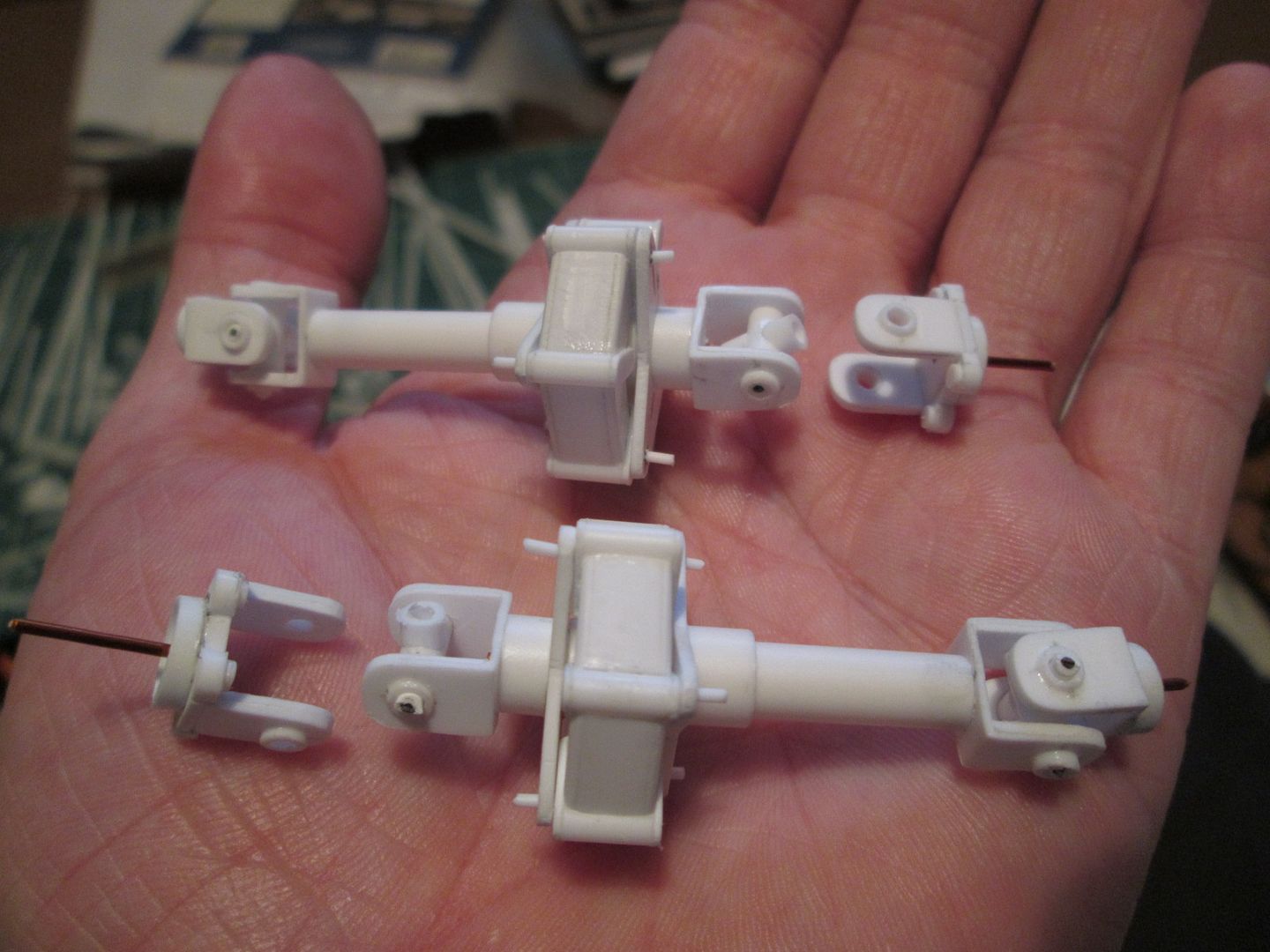
Here you can see the two complete shafts when assembled for a trial run. The spider flanges have been drilled through into the two donuts with short lengths of styrene rod used to hold everything together. The cross-shaped 'spiders' inside each joint are made from three short lengths of 1/8" tube, with pins pushed through from each end to allow them to pivot:
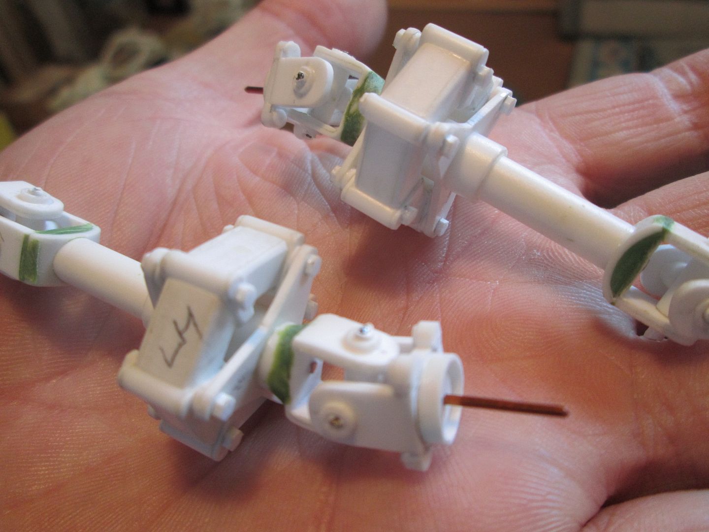
In this next photo you can see that I've added hex-detailing on both sides of the donuts, to create the nuts and bolts which would pass through the spiders. The outermost ends of the shafts have been given a curved underside (using a section of large-diameter tube cut to shape) with some greenstuff to fill the gaps.
The small pins pushed into the universal joints are not permament. Each shaft can still be broken down into parts to allow for easier painting (whenever that will be!). It's tempting to glue the donuts and spider flanges together now, but it would be very awkward trying to get a brush into the inside.
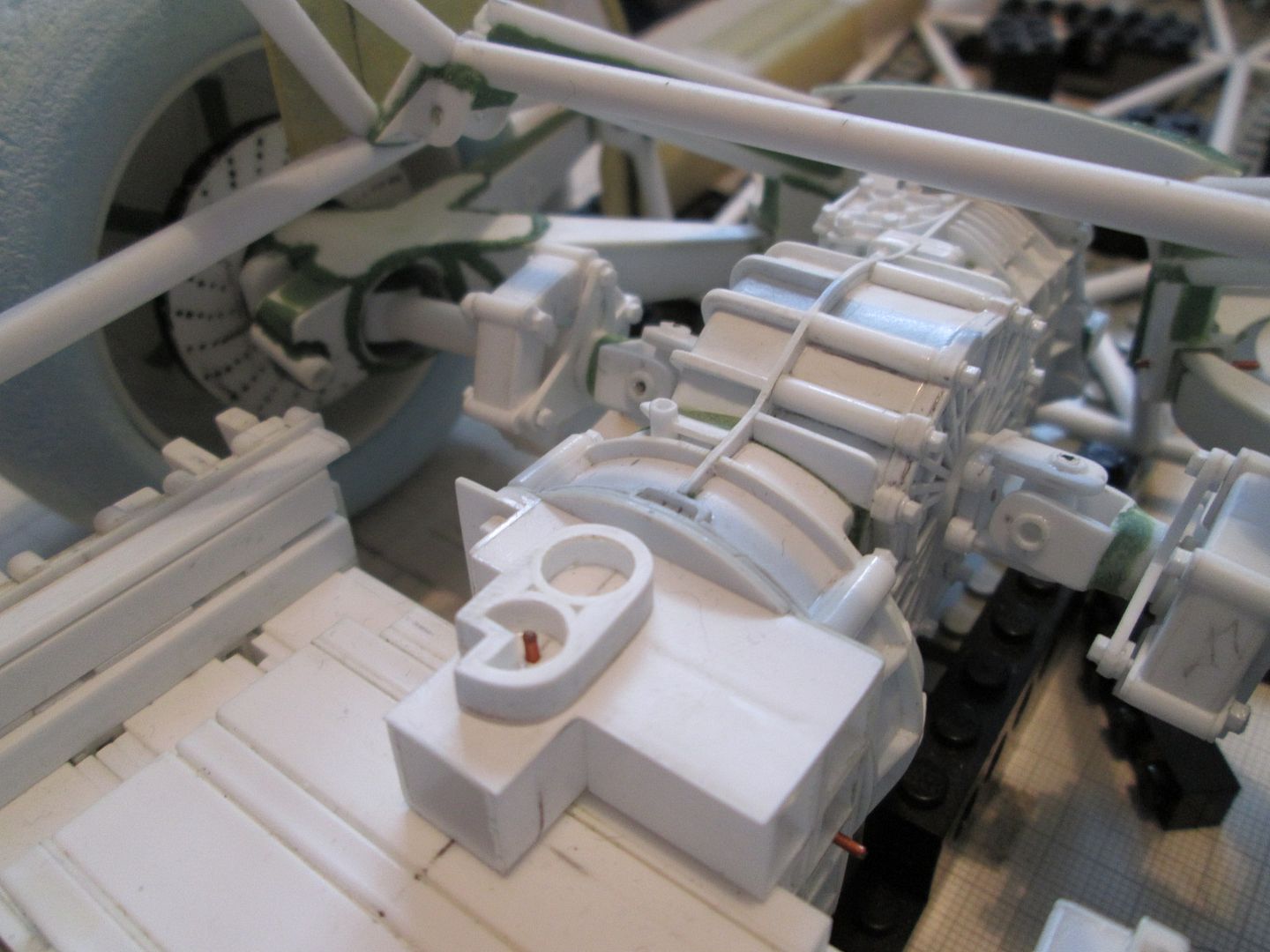
The next job was to re-fit the engine and gearbox and see how everything looks. Here you can see the two driveshafts with the suspension on full droop - note how the left-hand side clears the starter motor:
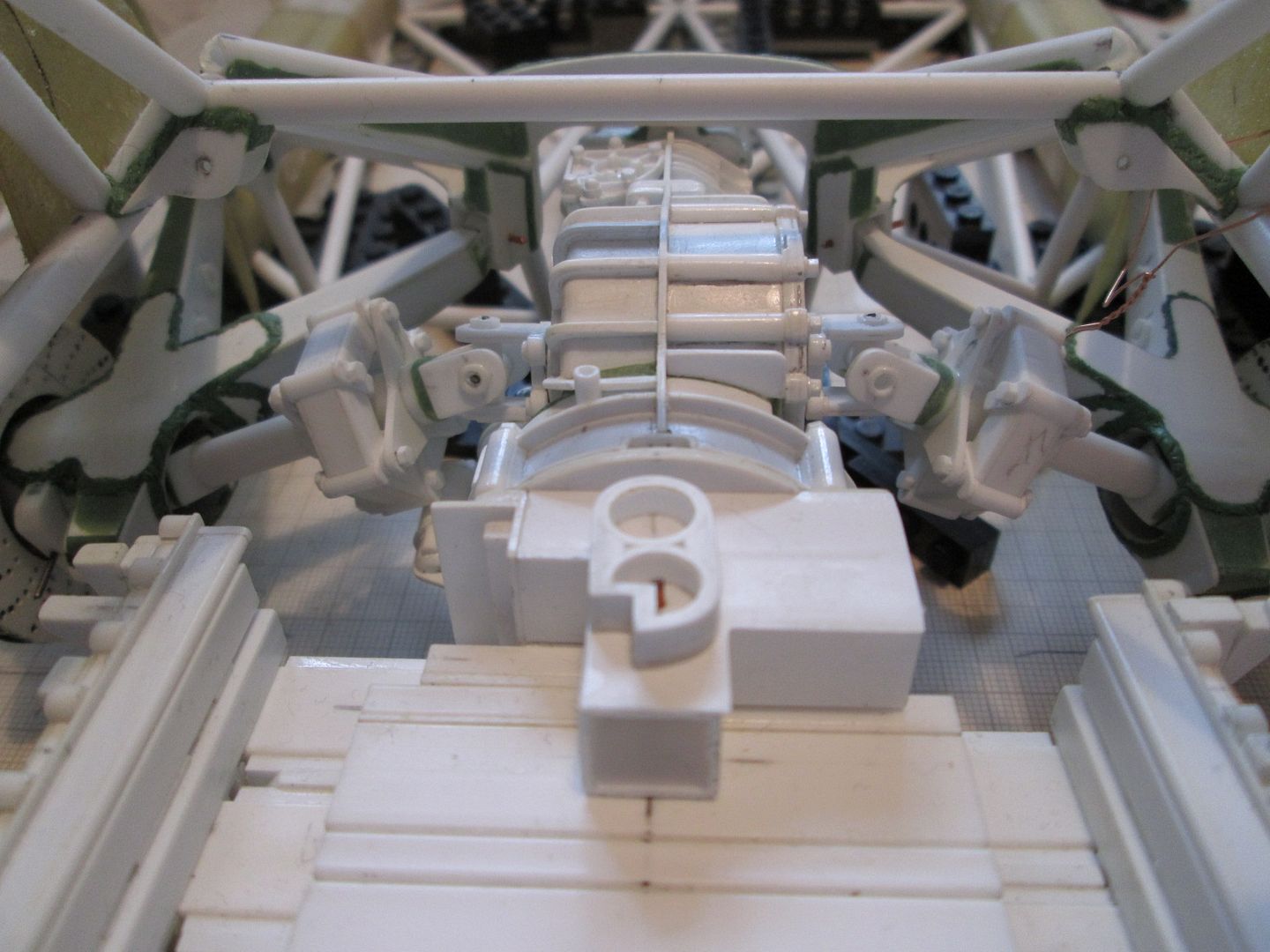
With the wheels fitted the driveshafts lift to a more conventional angle - just slightly below horizontal. The outermost universal joints are buried inside the trailing arms and nearly hidden from view - I could have saved some time and effort here by leaving out this joint completely, but that's not the way, right?!
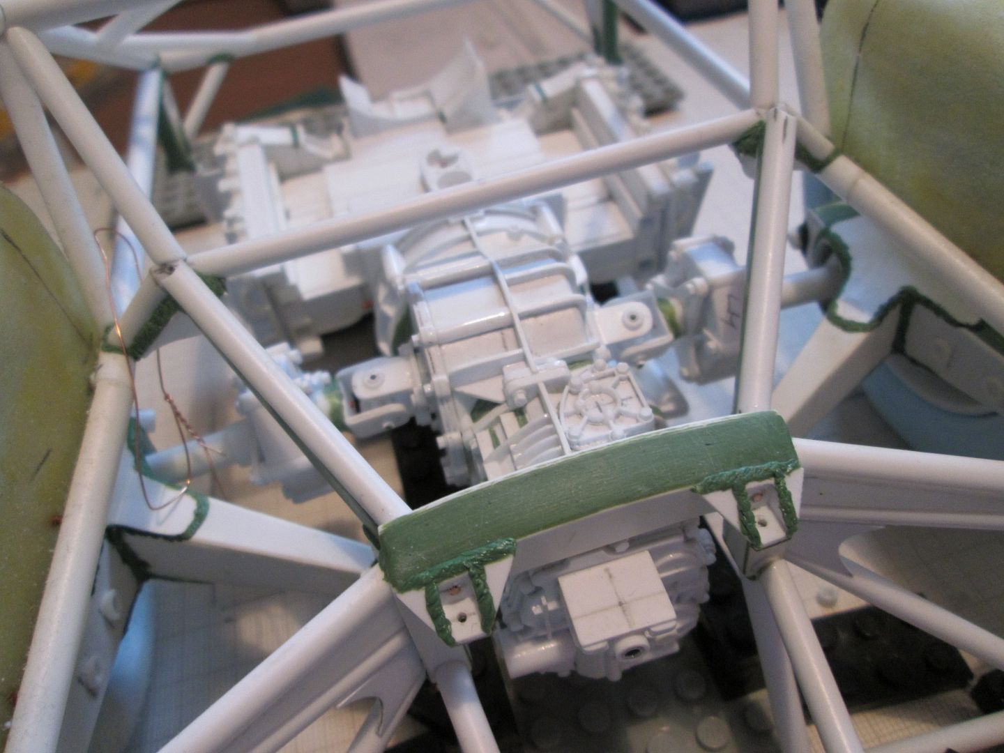
Another photo at ride-height, looking towards the back of the car:
So, at this point the two shafts are about as complete as they need to be (for now). Time to move on to the next job!
More at the weekend.
SB