Guys, thanks again :-) This build report is my "modeling book". I also doubt too many people would buy a book like that. Ask modeling magazines how many copies they sell these days. I think the WEB is a very good tool to do this but once i'm done with this build i think i will make one book for myself from the build report :-)
maxone... i use ordinary nitro thinner for the putty ( ZERO thinner works also ). I mix it with some of the white putty until i have the right viscosity and then add the red hardener. The thinner may slow the drying though.
Anyway, time for some more build progress.
I carried on working at the front end of the car. It was time for the suspension arms. I had to rework the lower front arms substantially. While I kept the rear chassis connector from Tamiya I had to change the one at the front because that will now be visible with the removable nose cone and should look like the original. Also the outer one had to be remade to connect to my new upright. I had to guess a bit because I dont have enough pictures of that area but it seems to be the same sort of connection the McLaren MP4/4 has at the top of the front uprights so I built it accordingly.
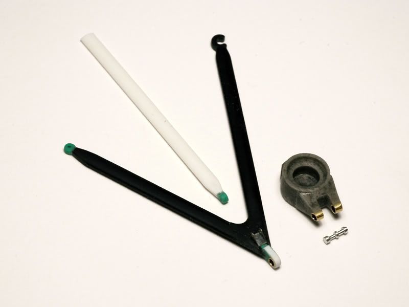
I used brass tubes for better strength and the little silver part is turned from aluminium.
The white part is the pushrod I scratch built from 1mm sheet styrene, because the kit ones werent long enough. Thats because the connection points of the suspension arms to the uprights are too close to the chassis on the kit parts. I made mine more like the real ones so the pushrods ended up being a bit short to later connect them to the front damper in the nose. I could have tried to extend the kit parts but making new ones wasnt really more work.
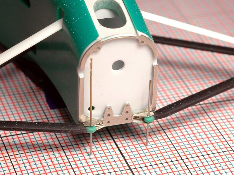
Next you see the arms held in place to the monocoque with two 0,4mm drills on photo etched brackets I made.
In the etched frame on the monocoque I also made two cutouts where the steering mechanism will later go.
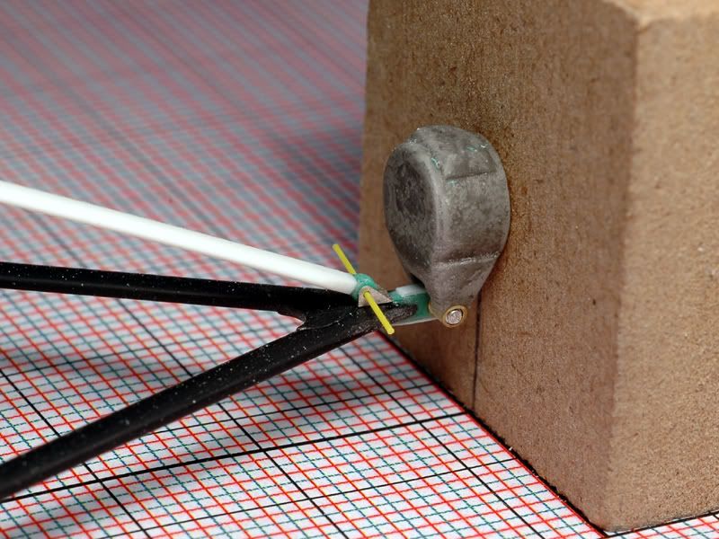
On the outside you have the arm connected to the upright which is held on the jig. The upright is connected to the arm with another etched bracket.
Finally heres an overview with both sides dry mounted.
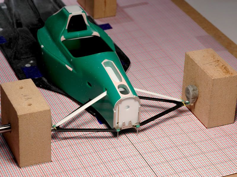
The jig was a really good thing to build. It doesnt speed up the build but makes it more precise. Only because I had it for reference, did I notice that the lower arms were about 0,5mm too wide in the beginning. That sounds very small but 0,5mm in the wrong place can really screw the whole suspension geometry and make the car sit wrong in the end.
Now I will have to do the upper arms and steering arms which will be at least as much work...
Because I was a bit annoyed with the suspension arms I also started working on the brake ducts. In the kit they are typically for Tamiya an integral part of the upright as I showed you previously.
Mine are separate for ease of painting and decaling and simply because theyre like that on the real car :-) I used the kit parts, thinned them out from the inside and then closed the channels with sheet styrene and added the shapes that connect them to the upright and funnel the air with more styrene sheet a turned bit of renshape and some polyester putty.
Here are two views of the left side duct. Now I have to make a symmetric one for the right side
.:-)
So much for now and thanks for looking!