For the LED conversion you will need LEDs, resistors and the factory bulb holder(s), a soldering iron and some sodler, and heat shrink tubing, and Kneedle nose plyers.
If you aren't good at soldering, you probly wont want to try this.
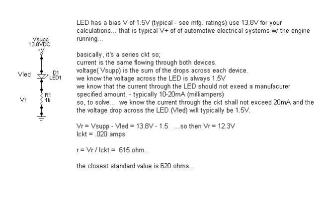
Depending on what voltage your LEDs are deciedes what size resistors you will need. Here is a pic with the formula I used.
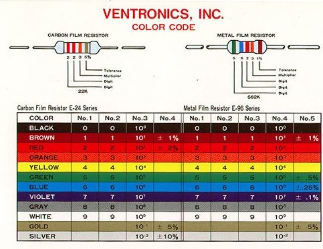
This chart shows the color band for resistors.
So your average car puts out aprox 13.8 volts, and if you have 1.5 volt Led's w/ %5 tolerance @ .02 milliamps here's what we get.
Vr=Vsup-VLed
13.8-1.5=12.3volts(Lckt)
12.3/.02 = 615 ohm
Ok we'll do some other variances with different LED voltages.
13.8v-2 = 11.8volts
11.8/.02 = 590 ohm
13.8v-2.5 = 11.3
11.3/.02 = 565 ohms
13.8v-3 = 10.8vlts
10.8/.02 = 540 ohms
Now they dont make every single one of those resistors, so you have to round down, or the nearest.
I used a assortment pack of LEDs ranging from 2-3v.
So I went for the middle of 2.5v which was the 565 ohm, rounded to the nearest resistor that was available was 560 ohm. Radio shack 5 or $1.
Ok using the previos post to remove the bulbs.
- Remove the factory bulb by lifting out the wires, then pull bulb out the top. Then using the plyers bend you LED wires(gently) like this.
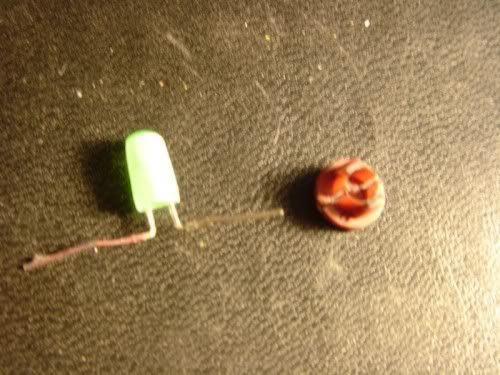
LEDs are a one way circuit so the longest wire is the positive, you might mark this one red to help later when installing the bulb.

Bend ends over toward the middle then cut off the excess wire. Should look something like this.
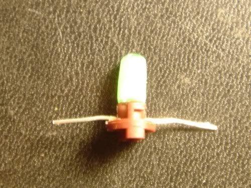
You might have to file/grind off a little bit of the LED to get it into the fixtures. I dremel tooled my fixtures .

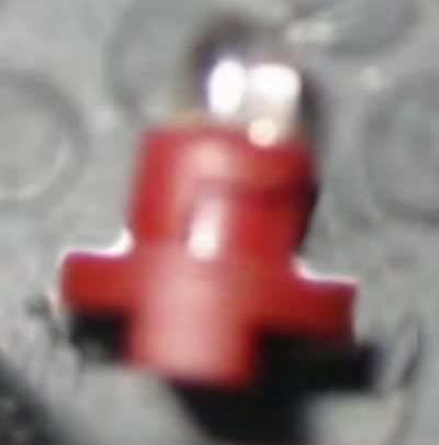
Here is a pic with the LED installed in a lock button.
For the drivers bulb is the same as aboe just a larger base.

Now for soldering the resistors.
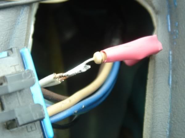
Starting with the pass side door lock, its the gray wire. Cut it about 1.5" from the switch, allowing enough room to solder the other end, these wires are short/tight.
The window button has two gray wires going into one, they all need used.
You will want to put your heat shrink tubing on before soldering both ends.


For the drivers lock is the same as above, the window button is the gray wire, two different sets here, you want the "A" wire which is also two wires like the pass side.

Twist the two together and solder your connections(same with pass side.

Installing the pass side bulb ......
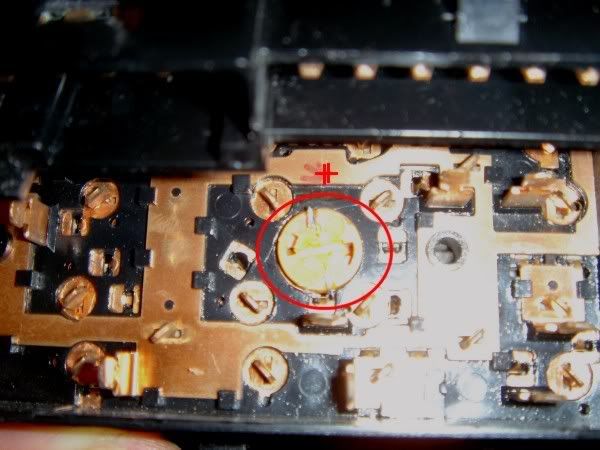
Here is the pass side window button with positive side marked with the red "+". You can verify this by the grey lead wire on the plug in.

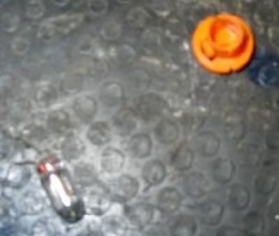
Pass side lock ...

Installing the drivers window bulb.
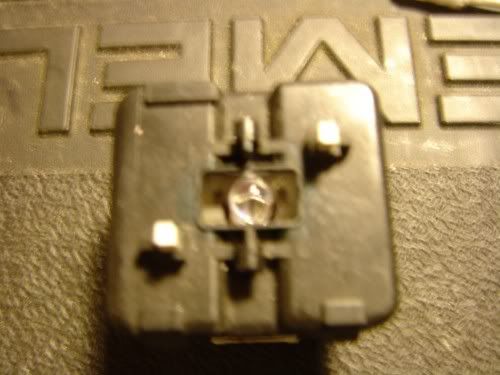
Looking at the switch ciruit, you can see I hav marked the positive side, this is where the positive side of the LED needs to make contact with.
Here is another pic with out the LED

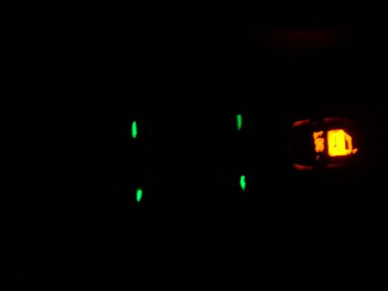
Once everything is back together they should look something like these....
If you have any questions, feel free to PM me or post your question(s).