A small, haphazzard and inconclusive update.
First the seat. This is the kit part.
(Thanks to Micha for provding a photo od his since I forgot to take one

)
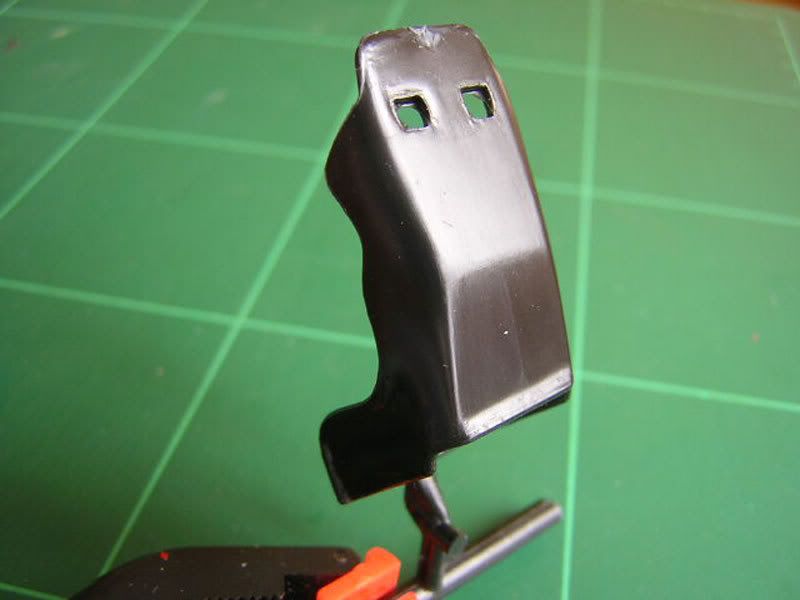
I hope that motor sports experts here won't prove me to be totally wrong on this, but looking at more or less period correct reference pictures the kit part didn't seem very accurate. Photos showed that there is some kind of covering on the seat that leaves a ridge around the seat back.
Since my personal target with this build is to get acquainted with putty, that's what I used to try and do something about it (I did consider stretched sprue, but I still can't get the hang of that

)
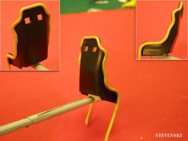
Using Tamiya 2-part epoxy I made a long sausage. To ensure a perfectly uniform thickness, I rolled it out on a piece of wet glass using a second sheet as the rolling pin (I hope this is clear what I mean) and this worked beautifully!
The long sausage was gently draped around the back of the seat being careful not to push too hard and left to dry out over night. When it had dried out, I trimmed the ends and fixed into place with thin CA glue run along the seam.
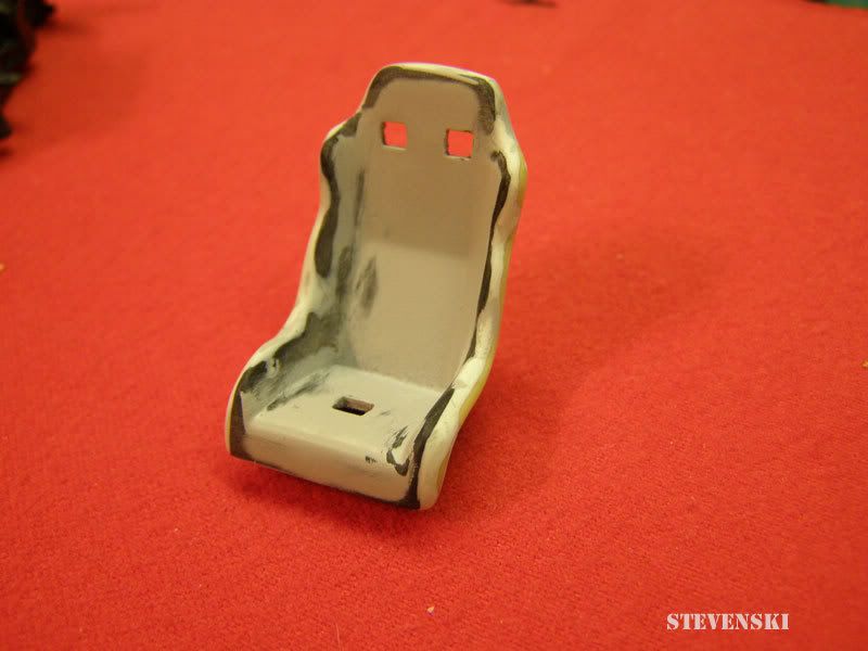
Next I used some Smooth Type Tamiya epoxy putty to mold the kit to the new edge. This took a few rounds of sanding/prime/smoothing to get right.
And here is the near final result in primer.
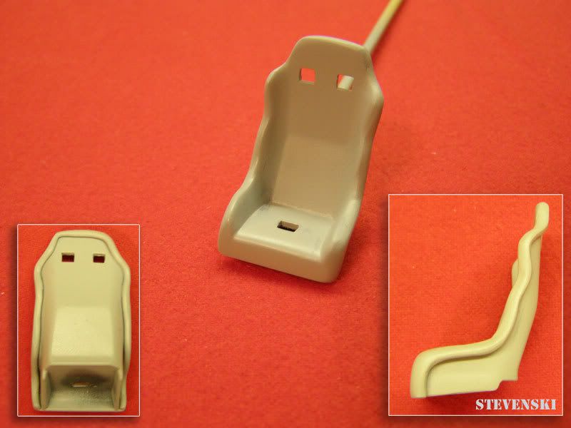
Before I do anything else to this I need to establish if it had 4 or 6-point harnesses. If the latter, I will need to cut out slots in the side.
Next up for no particular reason was some engine parts.
IMO a very distinctive element of the M1 engine bay is the air intake array.
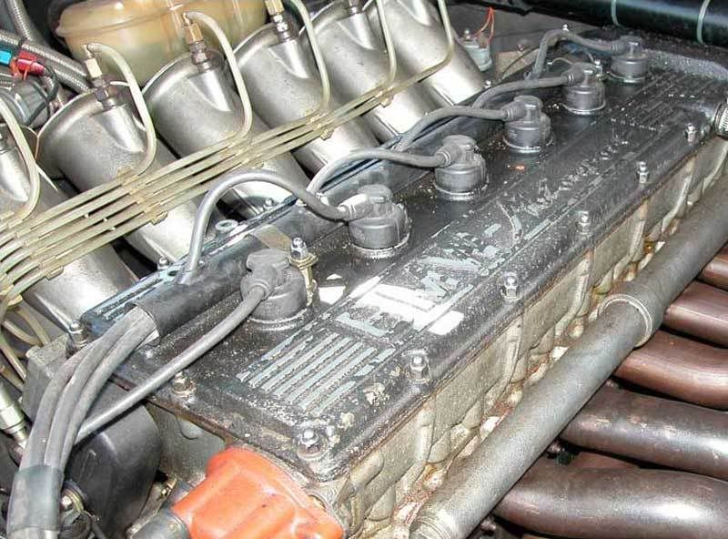
A row of wonderfully shaped and detailed breather tubes!
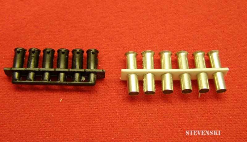
Revell provide a row wonderfully un-shaped plastic blobs

My initial idea was to try and recreate the whole part.
My attempt quickly told me that without some real precision tools (like a lathe

) this was going to stress me out big time and would probably fail.
So I decided to use the kit part as a base to provide accurate dimensions and fit to the engine and build on that.
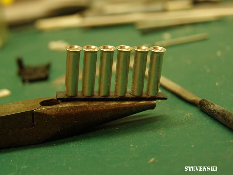
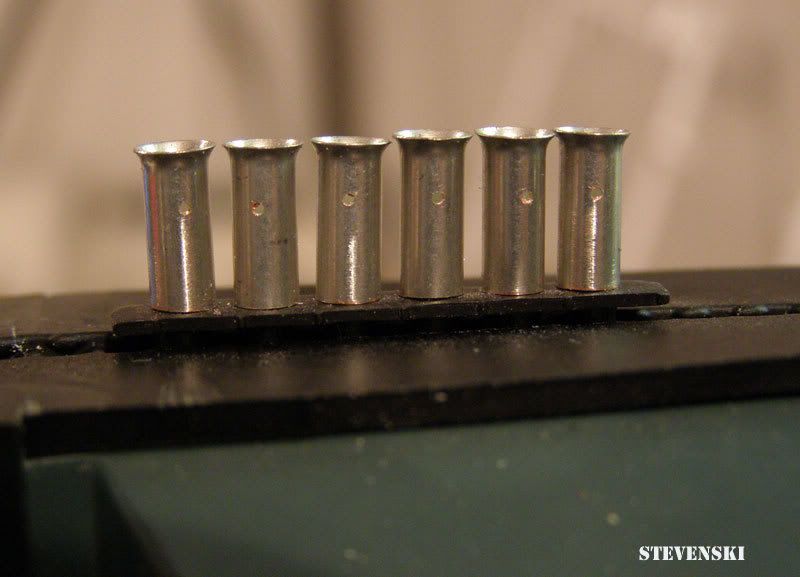
The key for this modification to look better than the kit part is not so much the individual breather tubes but uniformity in all 6 together they need to look like a row of perfectly turned out soldiers on parade
The strategy I came up with to achieve this was to gradually build up a row of pegs to put the tubes on.
I centred out the part, marked of 6 equally space points and drilled 6 0,3mm guide holes. These guide holes were then drilled out to accept a piece of styrene rod. Slices of styrene tube (with an OD fitting the ID of the breather tubes) were fixed on the rod. You get the picture, I guess.

The new breather tubes (same lead boot thingy-bobs used on my Super7) then just dropped into place.
The next job was to work on the breather tubes themselves. They need to be trimmed to size and drilled out to accept whatever I can think of to reproduce the injector valves (if that's what they are?). IMO uniformity is even more critical here - any irregularities will stand out like a sore thumb here!
Sadly my 2 lathe owing buddies are thousands of kilometers away and have proven records of loooooooooooong delievery times and I want to finish this build sometime this year
j/k
I decided to make a jig for the job using a larger sized breather tube which was cut to size and (after a couple of attempts) drilled with a guide hole.
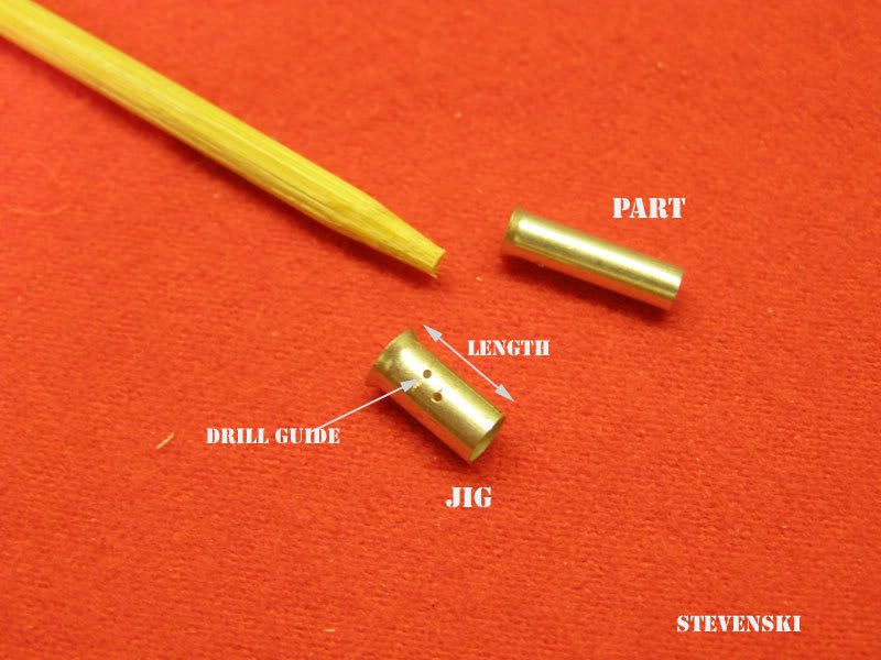
The smaller tubes were then slid inside, clamped in place with my left had and a bamboos stick while I cut and drilled with my right hand

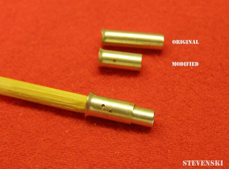
It actually worked quite well I think and here is a dry fit of the modified tubes sitting in their new home. There is some fine tuning to be done but I think it worked.
So far so good. Next to come is to work on the injector valves.
I won't share with you my 100% failed roll cage :[ I think I am going to give that a miss unless I figure out how to fix it inside the tub...
Thanks for looking and you're up again CeeElle