Another two weeks gone ( already ) and here comes a new update. I didnt do a lot of bits but some really complicated and time consuming stuff! I finally had to tackle the rear suspension. I had kept working around this up to now because I knew it would be tricky:-)
To make things worse, while taking measurements I realized ( as I mentioned in my last update ) that the top of the gearbox was too low relative to the body parts that sit between the suspension arms and the rear end of the cowling. First I thought I could just raise the whole engine a bit to fix that but then the lower parts would have been too high relative to the undertray. O.k
..were talking of around 1 to 1,5mm but in scale that makes a difference. After checking around my pictures it turned out the cast in stiffeners of the box top could be a bit higher and still look right. So I raised those features with styrene bits.
Like this the suspension pieces would come higher as well and the rest ( if necessary ) could be fixed with them. I also found another thing to fix while doing all this reference checking.
In the Tamiya kit the rear dampers sit on the flat sides of the gearbox but in the top view of the real thing that comes a bit further down the post you can see theres actually an indentation in the casing on both sides. I cant tell from my pictures if it really goes all the way down but later this will hardly be visible anyway. Without it I would have had trouble soon after fitting everything together.
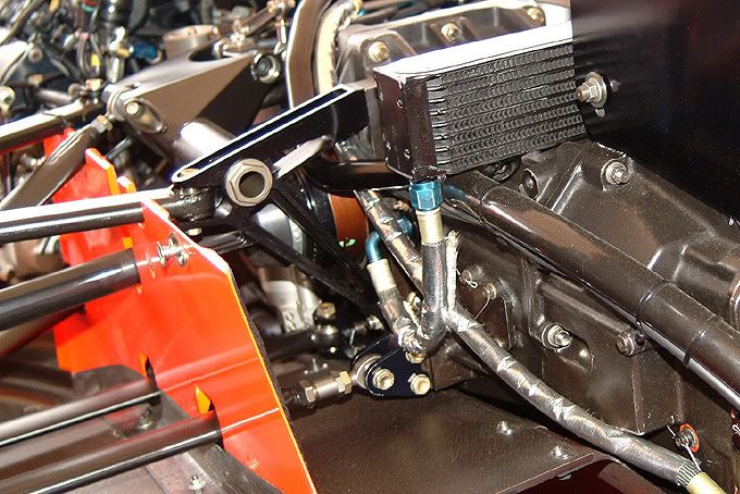
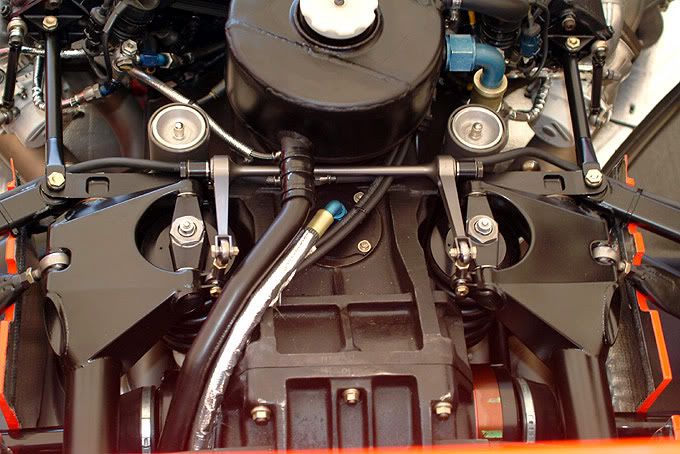
Theres a forward and rear subframe on each side that hold a turning element which connects them and the pushrods with the dampers. You can see the assembly on the real thing in this picture. This looks nice
but very complicated ( and heavy ) compared to the layout on current cars.
In the next picture you see the scratchbuilt model subframes. After my failed attempt to do them in brass I gave it a try with Ureol because thats stronger than styrene. I then found out its also nicer to work with for this application and I think Ill use it more often now.
The upper parts are the forward arms. I wouldnt bet on their shape being correct because in my photos they are mostly hidden by other parts but that will be the same on the model so who can tell :-)
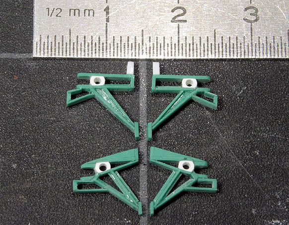
The arms are made from 0,2 and 0,4mm thick bits superglued together. This involved a lot of sanding and filing but ultimately worked out fine. The front and rear arms are built up from 13 and 17 individual pieces respectively
.quite some work. This really put a miniature CNC-mill very high up on my wish list
.. seems I have to start playing the lottery:-)
So far the pieces still look a bit messy in places but some primer and careful sanding should fix that.
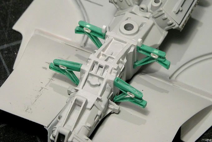
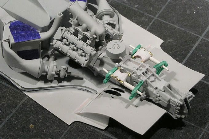
In the next picture you see them sketch glued to the engine/gearbox that I finally primered in the meantime.
Next up is the top view of the real assembly that I mentioned before, taken from over the rear wing. Theres a lot going on!
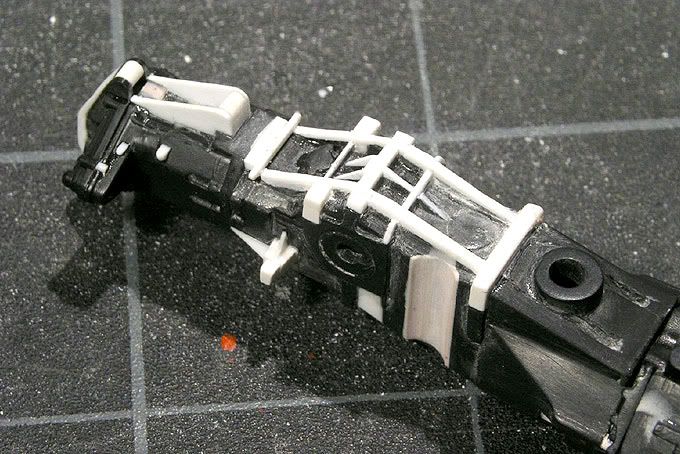
My next step were the pieces that run longitudinally between the arms and connect the vertical dampers with the pushrods. I have no idea if they have some technical name but I guess you know what Im talking about
:-)
I had made these two already some time ago and of course now they didnt fit exactly
.
Thats the problem with scratch building these things
.you basically have to build everything at the same time to make sure it fits or you have to change some pieces later on. I was lucky though and didnt have to rebuild them. I could correct the boxy parts that hold the dampers and now they fit. Here you see them test mounted together with a bunch of other primered engine pieces.
Now I can also carry on with the rear dampers and fit them.
After that the exhaust pipe will follow but to know where this will go I turned my attention back to the undertray.
After rebuilding the rear end of it at the very beginning of this project the original exhaust was gone but it was crap anyway so now I had to rebuild it a bit nicer. Normally you dont get to see this area of a F1 car ( especially these days ) but luckily there was one MP4/4 high up on display at Goodwood last year ( see the very first picture of this thread ).
I almost missed this opportunity at the show but late Saturday afternoon when they had closed the access below the display for the evenings party guests I still managed to get a shot with a tele lens.
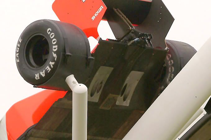
Funny enough the vertical diffusor fins are missing on this one but you get to see the exhaust heat shields and skid block in the centre.
I built the fins from 0.2mm sheet styrene using the original kit pieces and some other photos as reference. The skid block is a photo etched brass piece. The heat shields would have been obvious parts to be etched too, but when i did the photo etching I thought I couldnt pre-decide the shape of the holes for the exhaust pipes without having the actual holes and that their elliptical shape would develop when drilled in the undertray. ( Jeeez that sounds complicated
but I guess you get what I mean ). Anyway I was wrong :-(
After drilling the holes they looked nothing like on the real car so I shaped them like on the picture with a lot of careful filing and sanding. The heat shields are made from 0.1mm nickel silver sheet and i had to be very careful not to bend them in the process.
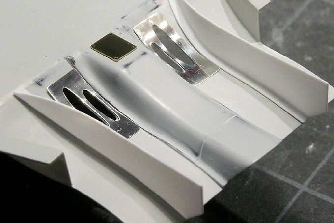
At the moment they are polished but theyll lose their shine later on and get some rivets.
Thats it for now. See you at the next update:-)