A new update
..finally
and a special welcome to the F1M members who lately found this thread :-)
Work has been going on slowly but surely with the model due to things getting a bit tricky in places and a lack of modeling time.
I have worked on various bits especially in the engine bay and they have to be test fitted a lot because at some point everything gets connected
and that takes time. I also stumbled over a new problem with the kit pieces and their relative sizes that I have to solve somehow soon
but Ill get to that in a bit.
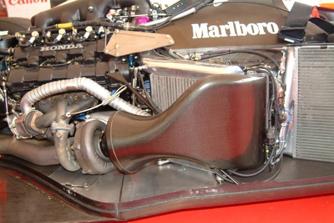
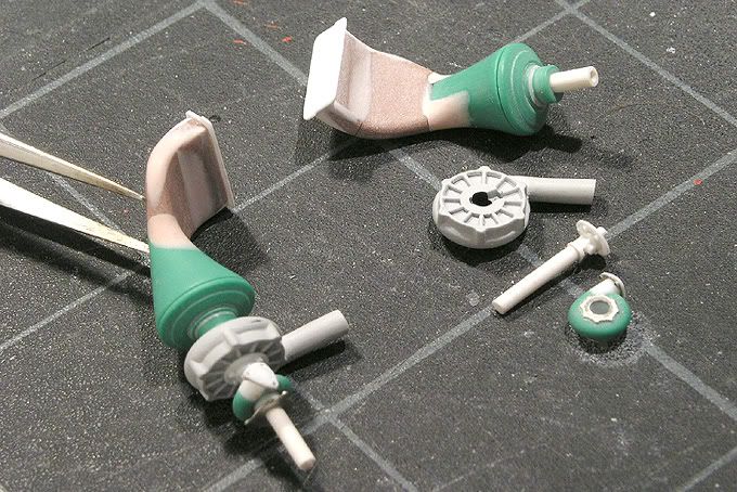
First up heres a shot of the turbo air intake as it runs from the sidepod towards the turbo. Again thats the main difference of the MP 4/4 late version compared to the early one with the periscope airduct sticking out on top of the sidepods.
My original plan was to use the kit pieces ( the white one in the next photo ) as a starting point but that wasnt going as smooth as I thought so I decided to rather scratchbuild the things from Ureol which is nicer to work with than styrene.
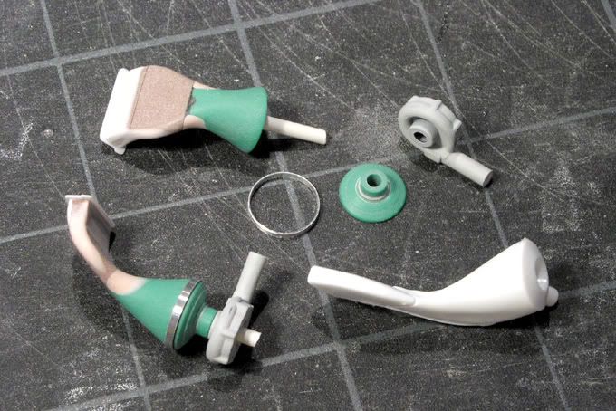
The shape is quite complicated but with a bit of patience its not a real problem. The green parts were turned on the lathe separately because the front part will later get a CF pattern and the round part is just black. You can see that better in this view.
The front parts of the turbos ( which compress the fresh air for the engine ) are the kit pieces. They are pretty good and I only cleaned them up and extended the tubes that run towards the intercoolers.
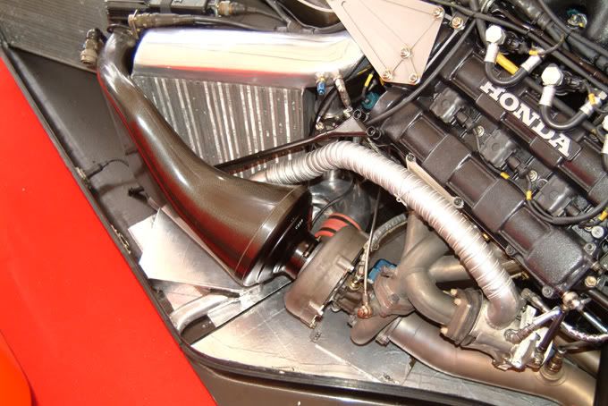
The housings for the smaller turbines that are driven by the engines exhaust gasses were pretty rough black blobs on the kit pieces. You see them here connecting the exhaust header and pipe.
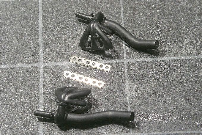
Theres a lot of neat detail in this area on the real car and I want to replicate that as good as I can. First I tried to improve the existing bits but that didnt work out because they were a bit too small in relation to the surrounding elements
and my PE bits:-) After wasting some time there I decided to scratch build them too with turned Ureol and styrene rods of various sizes plus my PE details. Everything can be stuck together which makes test fitting and later the buildup after painting easier and more solid.
Next up to build are the exhaust pipes and of course the headers that connect the turbos with the cylinder heads plus some other plumbing whose use I dont really know :-)
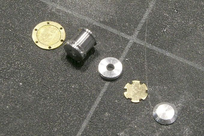
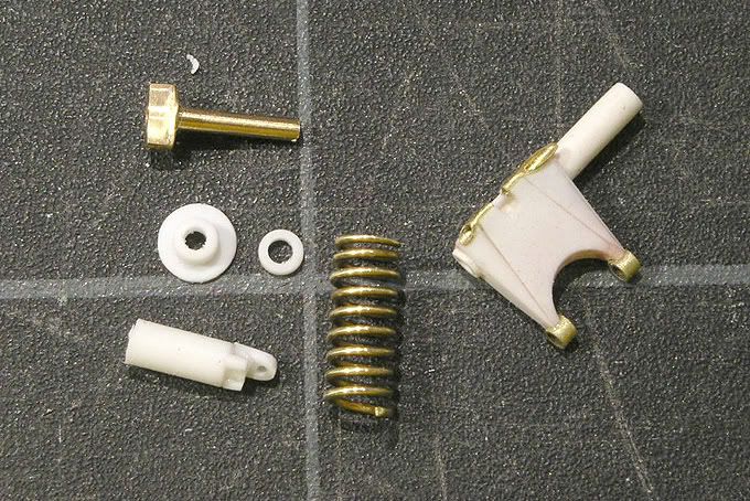
In the next picture are the machined and photoetched pieces for the turbo wastegate. This will be a bit nicer than the plain cylinder that comes in the kit
..once its painted and assembled :-)
I also worked on another area. These are the machined centre pieces for the dampers. I first turned them on the lathe and then cut out part of the top ends on the mill.
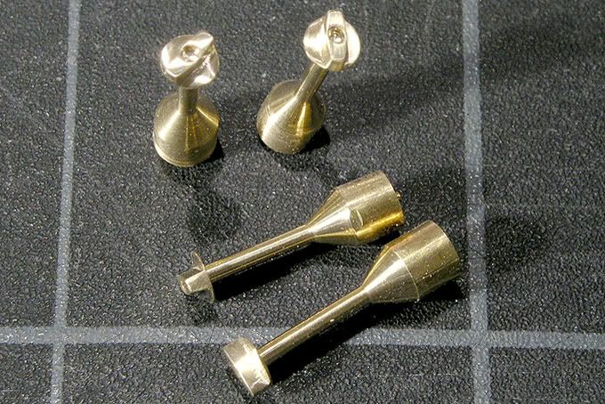
I almost messed them up because after turning the shafts thin in the lower part before milling they were too flexible and bent but I could save them with some careful filing and sanding by hand.
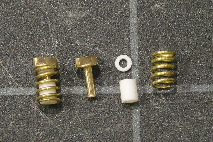
In the next picture are the front dampers with the fat lower ends I used for fixing in the machines cut off and additional bits made from styrene rods. The springs are made from 0.5mm brass wire. I wound them around a 2mm styrene rod and first they were quite uneven in shape. I then pressed them together with tweezers and heated them up with a lighter to get the stresses out. After that it was easier to get them bent out again to a regular shape. The lower end of the front dampers wont be visible later on so they are shorter than the rear ones.
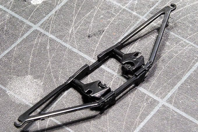
The pieces of those are in the next picture together with another part of the rear suspension I made from sheet styrene and brass rods. I cant finish them yet because I first have to build the rest of the rear suspension to figure out their exact length.
Heres the original part from the kit
not nice enough:-)
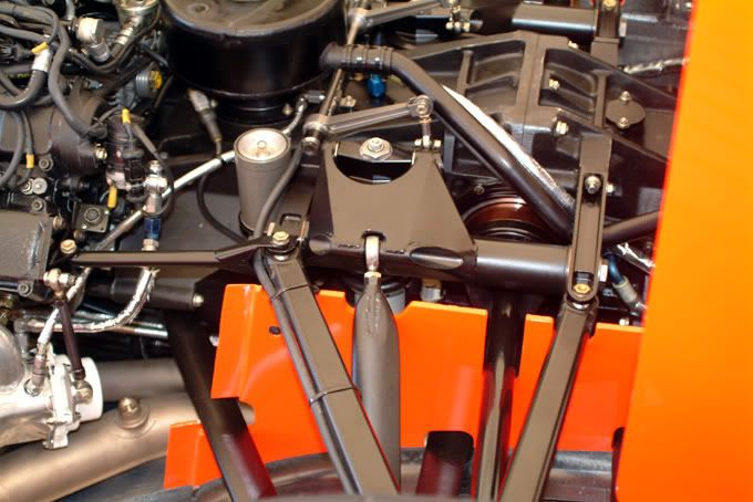
The real suspension looks like this:
While trying to build the first pieces for the rear suspension subframes from brass ( didnt work as I wished so Ill try something else
.i hate soldering !:-) I stumbled over yet another problem of the kit. The top of the gearbox is too low relative to the cowling and the side body parts the rear suspension arms are running through. I havent really figured out yet what to do to solve this but I dont want to change the suspension geometry like Tamiya did in their piece. Ill probably get into more detail in the next update
if I decide what to do about that :-)
In the meantime while I was on the lathe I also made these pieces for the driveshafts.
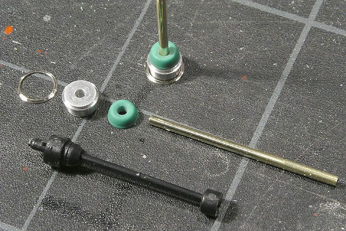
The shafts are 1.5mm brass rods. The thin ring is a cleaned up PE bit that will later be anodized red.
Im really looking forward to get going with some painting and not see all those raw pieces on my table anymore, but so far theres some more basic stuff to build and test fit before I can do that. Otherwise im afraid Ill only ruin stuff thats already looking nice.
Thats it for now:-)
P.S.
Steffen
.i could sell you some of those wheelnuts
.but i guess you wouldnt like the price :-)