Hi everybody. After christmas holidays here comes a new update. I did manage to get some stuff done although not as much as I thought :-) Anyway here we go!
After my photoetching session I first shifted attention to another big obstacle
.the wheels. The kit bits come like this:
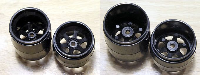
They are a good starting point but obviously need some attention. As I started checking my reference pics though, some questions arose. As you can see the wheel has 5 spokes instead of 6 and that was the case for both the MP4/4 chassis I photographed!?
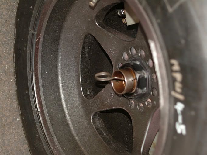
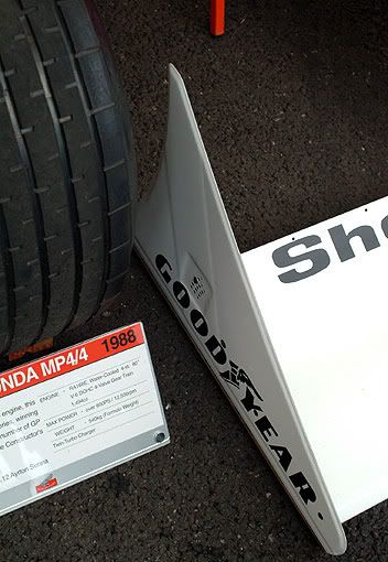
From my reference books though I looks like the cars always raced with 6 spoke wheels. Luckily Honda had those wheels on a MP4/5 at Goodwood in 2003 so here are shots from them which I used as a guide.
My aim for the wheels and the rest of the suspension is to get them very detailed to keep them on level with what I want to do with the rest of the car. I does make you feel a bit stupid to build stuff that will mostly be hidden inside the wheels but where do you stop? :-) The uprights definitely will need attention where they get connected to the suspension arms later on because theyre clearly visible so the rest has to follow
The solution to that problem is quite obvious
the wheels must be detachable. Tamiya provides that with their screws into the upright solution
well kind of :-) Its of course completely wrong because there has to be a centre wheel nut that goes onto a stub axle. So
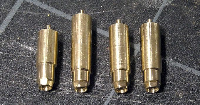
i have to make my own working ones. In fact these here are my second attempt. I did that whole stuff for my MP4/8 already using brass hex rods ( and then stopped working on the model to do this one here
) but what comes now is an improved version.
Plastic is no choice for fabricating those pieces so I used brass again. I started with 4mm round material that I turned to an outer diameter of 3.4mm and drilled holes inside, to then cut a M2 thread.
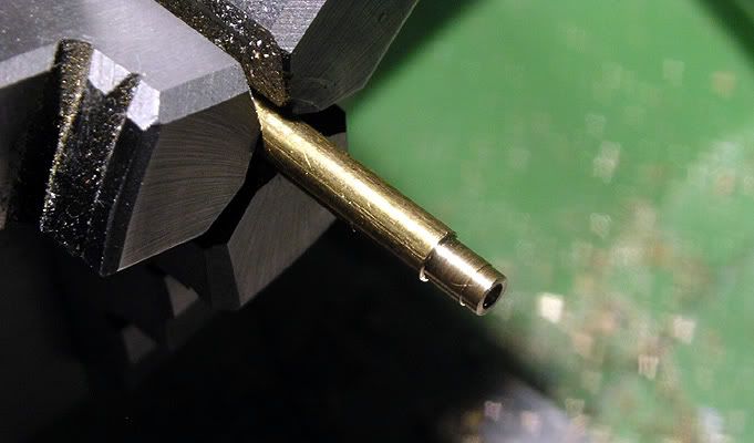
The next step was to mill the hexagon shape for the nut using a partition head. I couldnt figure out its name in English but its a device where you fix your piece in the middle ( like on a lathe ) and then you can turn it around with a degree scale for reference to make partitions
.i hope that explains it. I dont have a photo to show because I dont have a mill yet and couldnt take any during the working process. Anyway after milling and some cleaning up with 1200grit sandpaper and 3600grit polishing cloth my wheel nuts looked like this:
Next up they went back into the lathe and I cut them off at the back with an angle that fit to the one I put into the front of the wheels. The result is here:
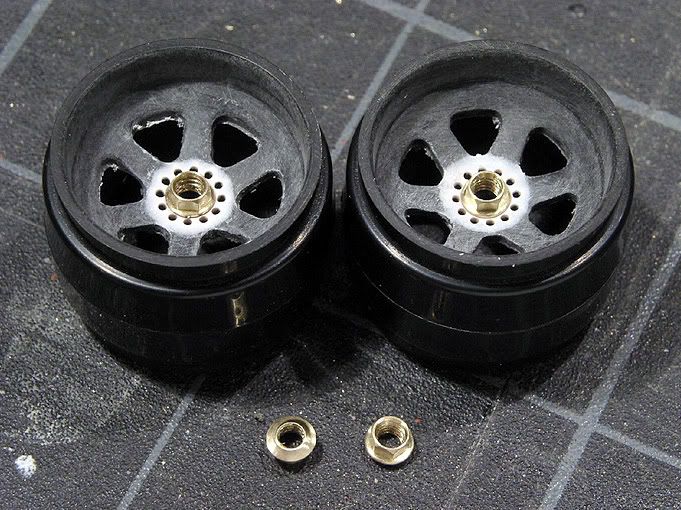
As you can see I filled the front of the rims with polyester putty. Then I drilled a 2mm centre hole on the lathe and made the surrounding little holes using again the partition head and mill. They go all the way through.
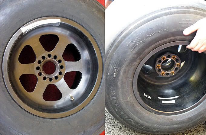
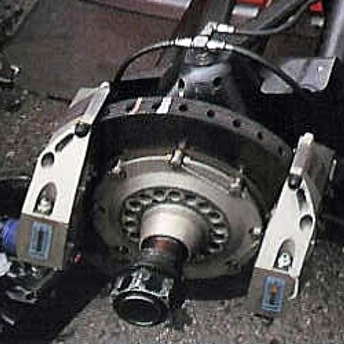
Here is a picture off the web from the real cars hub/brakedisc/upright assembly. ( Its a detail of a Rainer Schlegelmilch picture. I dont have much more because at Goodwood they always left the wheels on the cars while I was there..:-(
In the following picture you can see the pieces I made for the model spread out in front and sketch assembled in the back. Theres the wheelnut, stub axle and two photoetched pieces all made from brass. The axle is drilled hollow like on the real car. The thread is not really in scale but as good as I could get it. The fat end of the axle will go into the upright ( fixed with the little green ring ) and should be turning in the end while the wheel is fixed to axle, brakedisc and hub with the wheelnut. Thus the wheelnut will correctly turn with the wheel and not stay fixed like on the Tamiya solution
and I think it looks better:-)
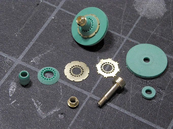
The green stuff I made the other pieces from is a polyurethane material used in professional model building. It comes in different densities ( hence different colours ) and is way better for milling and turning than styrene. Its from the same family as the yellow foam in cans for house building and is sold for example as Ureol or Necupur.
Originally I wanted to use the photoetched bits as drill templates for the holes in the wheels and hubs but that didnt work as planned so I made them on the mill along with the ventilation holes in the brake discs.
To make these assemblies go into the wheels I had to change them from the inside as well. I extended the centres with these green rings and made larger and deeper holes on the lathe. During that process I also got rid of the ejection pins on the backsides of the spokes and filled up the insides with putty. This I drilled out with a round milling head from my rotary tool ( aka Dremel ) on the lathe and then spent a lot of time cleaning/sanding by hand which is a really annoying job. On the right you can see two rims after their second layer of primer. Now theres only some sanding left to do and then theyre ready for paint and the little brass pins I still have to do. Before that I have to do the uprights though which will include a lot of test fitting that could ruin a finished paintjob
..and Im not really looking forward to that :-)

While working on all this I also carried on with some other pieces. First up are the front wing endplates. The kit pieces are way too thick and also dont look exactly like the real ones. To get better detailed ones I made PE bits. They were already cleaned up and primed before I glued them to 0.3mm styrene sheets as you can see in this picture.
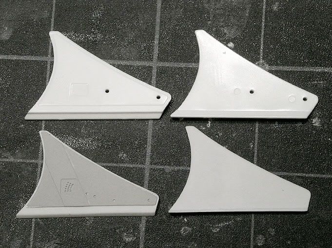
On the lower edge I added an angled strip of styrene that will later hold a wooden rubbing strip as per the original. You cant see that in this picture but Ill add one later when I get there:-)
Heres another picture after they are primered once more.
Im not going to drill the holes through yet. In fact I only put them in the PE bits because they would be really difficult to drill in those after painting. I learned on the 4/8 that even with sanding each paint layer theres a crater building up around each hole and that looks bad. Besides you have to redrill the holes after each layer of paint and that increases the possibility of messing them up
..i know what im talking about :-)
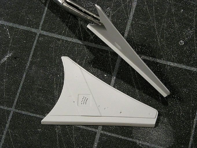
The same goes for the rear wing endplates. I rebuilt them from 0.3mm and 0.2mm (flap at trailing edge ) styrene sheet using the kit pieces as a template but without drilling the holes yet. I also added the angled surface running around the edge. ( In German we call that Phase but my dictionary didnt know that meaning of the word
..seems to be less important than knowing how to order food:-)
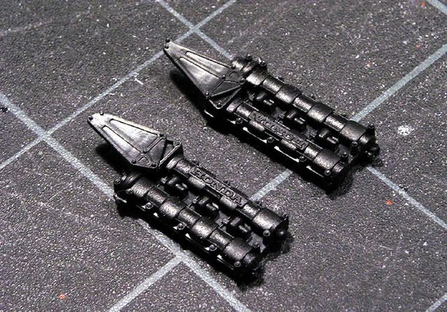
I also carried on working on the engine. The most prominent piece there is the plenum chamber on top.
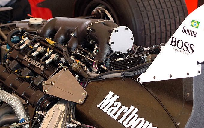
The kit piece that you see in the following picture together with the injection system thats supposed to sit underneath leaves a lot to be wished :-)

I worked on it a lot filing and sanding and adding detail with styrene rods, putty and PE pieces for the flanges. It is now filled from underneath and you can see through between the legs. Tamiya didnt have a chance to do that correctly due to the injection molding process.
While I was working on the little white bits in front of the first leg ( where the throttle linkage will go ) I realized the neck was too long. If you check the proportions in the last picture youll see what I mean. I decided to deal with it and leave it like it is because changing that would have meant it doesnt connect to the intercoolers anymore and I didnt wanna go there :-) The same goes for the cam covers. Their proportions arent exactly right but theres no way Im going to change them.
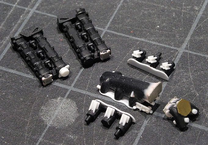
I did cut off the connector plates and the Honda script because theyll be replaced with PE bits and I added some details. The white bit on the left one is where the belt drive for the alternator sitting in the middle of the V is taken off. Thats one difficult piece Ill have to build.

You can find some great pictures of the engine at
www.gurneyflap.com . Im using those for details I cant see on my pictures but wont put them here.
I now have the engine bits you see here primered and they need some additional work for cleaning and Im working my way down to the exhaust and turbo assembly which takes a lot of time but I want them to look right and get them as clean as my patience permits
so for the moment this is it.
By the way
.in December I apparently exceeded my image hosting bandwidth because this thread is getting a lot of hits. I dont want to reduce the number of pictures really so just in case that happens again be patient
or dont watch them too often:-) They should appear again around the 16th of each month.
Cheers
Jaykay