|
|
|

|
|
| Search | Car Forums | Gallery | Articles | Helper | AF 350Z | IgorSushko.com | Corporate |
|
| Latest | 0 Rplys |
|
|||||||
 |
 Show Printable Version | Show Printable Version |  Email this Page | Email this Page |  Subscribe to this Thread
|
|
|
Thread Tools |
 06-27-2005, 11:36 AM
|
#1 | |
|
Resident Chemist
 
Join Date: Feb 2004
Location: Rockville, Maryland
Posts: 8,586
Thanks: 105
Thanked 157 Times in 157 Posts

|
Tacoma FAQs and Information - Search/Read Here Before Posting
ENGINE HISTORY AND SPECS
http://www.geocities.com/MotorCity/P...neEngines.html http://www.babcox.com/editorial/ar/ar400108.htm TACOMA/TOYOTA PICK-UP GENERAL HISTORY 1964 The Toyota Stout 4x2 is introduced to the American market. This is the first Toyota Pickup available from Toyota in the United States. 1969 Toyota introduces the Hi-Lux 4x2 with a 4 Cylinder 1.9 Liter engine known as the 3R. This Hi-Lux was quite plain compared to today's standards. Trucks at that time were primarily utility vehicles. The inside had only a metal dashboard, and a single bench seat. 1970 Toyota remodels the engine on the Hi-Lux with a 1.8L called the 8R-C. 1972 The 3rd generation Truck engine is released. It is a 2.0L designated 18R-C. 1973 This next model of Hi-Lux, actually released Spring 1972 (therefore a '72 1/2), took on a new look, much less utilitarian. The new car-like design gave it the quality of a Corolla, but retained its Toyota tendencies to be strong, reliable and inexpensive to operate. Styling changes included turn signals removed from the top of the fenders, and built into the body. As an option on the 1973 Hi-Lux, was a 7.5' bed. Prior to this huge step forward, hauling of this size could only be accomplished by full sized domestic trucks. This combination of a car-like ride and a Long Bed made the Hi-Lux a strong seller. 1974 The Hi-Lux wins the honor of "Pickup Truck of the Year" from Pickup, Van & 4WD. 1975 The 3rd generation Hi-Lux hits the streets powered by a 2.2L version of the 18R-C called the 20R and was also available (for the first time on a Toyota Utility Vehicle) with a 5-speed manual transmission. 1976 The US version of the Hi-Lux looses its name and is now known as the "compact truck" from this point forward. 1977 September 1977, the one-millionth pickup truck rolled out of the factory in Japan. 1979 The SR5 option is now available on the truck. With its 5-speed manual transmission and powerful engine, the SR5 was intended to appeal to a new type of customer, the sport-truck buyer. The 1979 model changes (noted as the 4th generation) were the biggest yet. The emphasis now was on passenger comfort while retaining its reputation as a true workhorse. The truck came in two wheel bases: short, and long, creating a real customized feel for the consumer. The biggest development comes as the introduction of 4 wheel drive. Prior to this year, all of the Toyota Trucks were 2 wheel drive. From this point forward, the 4x2 and 4x4 trucks are a separate product line. Most major modifications from this point forward are the same between the 4x2 and 4x4 unless otherwise noted. The biggest exception to this is that the 4WD model was only available in a 4 speed manual transmission. It was modeled after the Land Cruiser, with a solid front axel, leaf springs on all wheels, and a rugged time tested frame. Aftermarket modification kits such as suspension and body lifts, made the Toyota Truck a huge hit with off-roaders. The brand new 4WD model is a huge hit, winning the "4WD of the Year" award by Pickup, Van $ 4WD, "4WD Vehicle of the Year" by Off-Road, and "Toughest Truck of the Year" by 4x4 and Off-Road Vehicles. 1981 The Toyota "Legend" can now be found under the hood. The 22R engine that has made the Toyota Truck so dependable is born in the form of a 2.4L gasoline engine. In the same year, a 2.2L diesel engine was now available as well. Body modifications included the "one touch" tailgate. 1982 A 5-speed manual transmission is now available on the 4WD Truck. 1984 The 1984 model year represents the 5th generation of the Truck. Changes to the model continue along the car-like feel of the Truck. The Xtracab is now available for storage behind the seats, and the diesel and 22R engines both were available in a turbo-charged version. 4WD Trucks now come with an available option of "Shift on the Fly". This is a system where the front hubs can be locked automatically, without having to exit the vehicle. 1985 4WD Trucks now have an available 4 speed electronically controlled transmission. 1986 With the affordability of gasoline engines, the diesel engines are discontinued. To give the gas engines a little more boost, the Turbo-charged engine was developed. All trucks now come with Independent Front Suspension (IFS). 1989 6th generation trucks roll out available with a brand new V6 engine. With the optional V6, the Toyota Truck is now capable of towing 3500 pounds while still returning excellent gas mileage. "Rusty Bed Syndrome" of the older trucks was solved at this point as well. Changes in the Truck were few until 1994. Styling was upgraded regularly and new luxury options such as sport seats, air conditioning, and a CD player. The Truck remained as strong and versatile as ever, while still providing everything that a luxury car could. 1995 Toyota introduces an all new pickup truck, designed in Calty, Southern California, and built in Fremont California (at NUMMI) - The Tacoma. The Tacoma featured brand new high performance engines. A 142-horsepower 2.4L four cylinder with 160 lb.-ft. was standard on the 2WD models, while the 4WD models offered a 150 hp. 2.7L four cylinder engine producing 177 lb.-ft. of torque. On both models, an optional 190 hp. 3.4L V6 engine with 220 lb.-ft. of torque was available. This engine would be shared with the T100. The suspension was new as well. This redesigned suspension offered a coil spring double-wishbone configuration, which replaced the Hi-Trac torsion bar double wishbone suspension of the previous generation. The lower arm uses a closed cross-sectional structure that adds strength while reducing unsprung weight. Suspension travel on the 4WD models increased from 5.9 inches to 7.7 inches, improving both on and off road performance. Tread width on both 2WD and 4WD also increased, improving steering stability and ride comfort. The Tacoma continued to use the reliable leaf type rear suspension with refinements to layout design. For safety, a standard driver-side airbag, center high mount stop light, adjustable seatbelt anchors, improved side-view mirrors, and optional four-wheel ABS were added. Additionally, the Tacoma received side door impact beams, and three-point, automatic and emergency locking retractor (ALR and ELR) seatbelts in outboard positions, with an ELR seatbelt on the driver's side. 1997 While mechanically unchanged, the 1997 Tacoma gets a redesigned front-end. The headlights were faired into a new grille, and the whole assembly is more aerodynamic and stylish than before. The 4WD models Tacoma now has an available locking rear differential, bucket seats on non-SR5 Xtracabs, and revised striping on all SR5s. 1998 A passenger-side airbag is added one year prior to the Federal standard of 1999. For increased safety, the passenger-side airbag can be turned off with the ignition key. Accept for a redesigned sound system and the addition of new colors, the 2WD remains unchanged. 4WD models get interior changes including rotary HVAC controls, 2 additional 12 volt power outlets, and repositioned cupholders. Outside the Tacoma, a larger front bumper and restyled grille and headlights along with new overfenders give Tacoma a more aggressive look. Mid-year, the Tacoma PreRunner is introduced. This new 2WD pickup combines the rugged styling and off-road ability of the 4WD with the affordability of the 2WD model. The PreRunner was developed in conjunction with Toyota Motorsport's successful desert racing truck program. Much of the suspension tuning and development work was done with the assistance of Toyota-drive Ivan "The Ironman" Stewart. The PreRunner shares identical exterior styling with all '98 4WD models. They are available only as Xtracab models with an automatic transmission and a 4 or 6 cylinder engine. Enhancing the PreRunner and the 4WD off-road ability is an available Toyota Racing Development (TRD) Off-Road package. The package offers a rugged combination of front and rear Bilstein shock absorbers, locking rear differential on V6 models, progressive-rate front coil springs and rear leaf suspension, modified camber rear springs, a larger front stabilizer bar, 31x10.50R15 white lettered Goodyear tires, 15x7" alloy wheels, black overfenders, and special Off-Road graphics. 1999 The Tacoma PreRunner is available in a Regular Cab model with an automatic transmission equipped with the 2.7L 4 cylinder engine. 2000 Standard daytime running lights are added to all models equipped with ABS. Also, the Tacoma StepSide, a sporty package that added a youthful alternative to the Tacoma lineup. 2001 The Tacoma enters a new model year with an aggressive new styling change which include a new front fascia featuring a vertical grille, raised hood, new multi-reflector headlamps, and jeweled tail lamps. Inside, tether anchor brackets have been added to supplement child restraint systems. Also, several new upgrade packages, and 4 new exterior colors. The Double Cab is introduced. The Tacoma Double Cab delivers the cargo hauling capability of a pickup, the passenger roominess and comfort of an SUV and rugged styling that makes an aggressive statement. The Double Cab is offered in SR5 and Limited trim levels with available off-road package in the 2WD PreRunner series with a 4 or 6 cylinder engine. It offers 11 inches of ground clearance, and a 61" cargo bed. It's 4 large conventional doors open to a well appointed and roomy interior, featuring spacious front and rear seating and a 60/40 fold-down rear bench with 3-point outboard belts. The Tacoma S-Runner is introduced as a new Sport Truck. The S-Runner is offered in a 4x2 Xtracab trim level with a 5-speed manual overdrive transmission and powered exclusively by Tacoma's 190-hp V6 engine. Performance is enhanced with a low-to-the-ground sports tuned suspension with Tokico gas shock absorbers and stiffer springs, sway bars and bushings. Ground clearance is reduced by 2 inches from the standard 4x2. The The S-Runner boasts a full color-keyed exterior that includes the grille, lower valence panel, front and rear bumper, overfenders, and outside door handles and mirrors. For an extreme appearance, a dealer-installed Toyota Racing Development (TRD) body kit is available. The color-keyed exterior is complemented by an aggressive interior feel which includes standard amenities such as front sports and power lumbar driver seat, front seat for and aft adjustable headrests, leather steering wheel and shift knob, tachometer with twin trip meters, AM/FM/Cassette audio with 6 speakers, tilt steering wheel, variable intermittent wipers and a rear console box. Finally, the latest addition to the Tacoma family is the StepSide. This package is available on regular and Xtracab 4x2 models, powered by either 4 or 6 cylinder engines. The StepSides cargo box is a solid steel unit and the sporty image is enhanced by the use of front fenders, bumper and grille from the Tacoma 4x4. Notes So what does Tacoma mean? Tacoma comes from the Salish Indian word for the mountain that provided water to their tribe (later changed to Mount Rainier). The name suggests images of strength and power. What about PreRunner? Well, PreRunner is a term that refers to a class of vehicle that is used to "pre-run" an off-road race course in order to save the race vehicle for race day. Often these "pre-runner" vehicle are heavily modified 2WD trucks. The compact trucks (2 and 4WD) are built at the New United Motor Manufacturing, Inc (NUMMI) in Fremont, California, the Honsha Plant in Toyota City, Japan, and all truck beds are produced at TABC in Long Beach, California. 4WD trucks are also built in the Tahara Plant in Tahara, Japan. All Tacomas are manufactured at NUMMI. The StepSide pickup truck was co-developed by design engineers at NUMMI, Toyota Motor Sales (TMS) USA, Product Planning Group and Rob Millen Motorsports in Huntington Beach, California. The above data is provided courtesy of Toyota Motor Company, Inc.
__________________
Forum Guidelines:http://www.automotiveforums.com/vbulletin/guidelines.html "What we've got here is a failure to communicate" Last edited by Brian R.; 08-26-2005 at 01:01 AM. |
|

|
|
06-27-2005, 12:33 PM
|
#2 | |
|
Resident Chemist
Join Date: Feb 2004
Location: Rockville, Maryland
Posts: 8,586
Thanks: 105
Thanked 157 Times in 157 Posts
|
Re: Tacoma FAQs and Information
STARTER CLICKS ONCE BUT DOES NOT TURN ENGINE
Q: Often my starter will just click and not turn over the engine. It will do this for a long time, but eventually it will act normally. Is this a common problem with Toyotas? How can I fix it? A: Yes, it is a common problem with Toyota starters. Many times, the problem is sticking starter solenoid contacts. See the following links for descriptions on how to replace them. This is a really cheap and easy fix on a Tacoma and should be the first thing you try after you check all the cable connections and the battery quality. http://www.autozone.com/servlet/UiBr...3d8013e21e.jsp http://www.automotiveforums.com/vbul...d.php?t=166530 15 Toyota (NipponDenso now called Denso) starter-repair reference sites: http://www.off-road.com/4x4web/toyota/tech/starter/ - http://www.4crawler.com/4x4/CheapTricks/Starter.shtml http://char.tuiasi.ro/vw/reality/rog...s/Starter.html http://yotarepair.com/startercontacts.html http://www.toyotaoffroad.net/afertig...rterrepair.htm http://www.4x4wire.com/toyota/maintenance/starter/ http://www.yotatech.com/~corey/tech/...r/haveblue.htm http://www.sleeoffroad.com/technical...er_rebuild.htm http://www.startercontacts.com/install.htm http://www.startercontacts.com/image...ded%20view.jpg http://www.colorado4x4.net/tech/star..._contacts.html http://www.barneymc.com/toy_root/techneek/starter.htm http://perso.wanadoo.fr/adherence.4x4/start_bj.htm http://www.automotiveforums.com/vbul...d.php?t=166530 http://www.toyotanation.com/forum/sh...312&forumid=10 http://www.toyotanation.com/showthre...312&forumid=10 Starter contact kits (8mm ID hole): Ace Electric # S-5263 (only two contacts) Ace Electric # S-5264 (only two contacts) Metro # 66-82104 (only two contacts) (www.metroautoinc.com ,Pomona,California) Toyota # 28226-72010/80 (battery side)(also1KZTE-2LT-1KZT) Toyota # 28226-72080 (8808-9108) Toyota # 28226-16130 (9108-9308) Toyota # 28226-55050 (9308-9511) Toyota # 28226-70040 (9308-9511) Toyota # 28226-72040 (motor side if needed) Toyota # 28226-72010 (8808-9511) Toyota # 28226-74070 (9108-9511) For others besides 22R series: Toyota # 28226-54220 (motor side) (2LTE, 3L..LN13# IKZTE, 2L#, KZN130,LN108,112,85..4FC) Toyota # 28226-54250 (Diesel Surf 2.4TD, contains a new end cover and gasket) Toyota # 28226-54320 (battery side) (2LTE, 3L..LN13# IKZTE, 2L#, KZN130, LN108,112,85..4FC,3B-1HZ-BJ73-HZJ7#-1KZT-KZJ70) Toyota # 28226-17030 (battery side) (1H#-HDJ80-HZJ80) Toyota # 28226-56250 (battery side) (3B-1HZ-1PZ-PZJ7#) Starter contacts only (8mm ID hole): Ace Electric # S-5231 Ace Electric # S-5293 (crescent moon shape) Ace Electric # S-5295 (crescent moon shape) Metro # 66-82106 (www.metroautoinc.com ,Pomona,California) Tons more at: http://www.metroautoinc.com/PDF%20Fi...%20Contact.pdf Toyota # 28226-70040 Wilsons Electric # 45-29-652 Starter brushes: AC Delco # D762 GP Sorensen # 255048 Standard # JX-117 Whether your starter uses two rectangular types or one rectangular and one crescent you can substitute with two squares or one square and one crescent so any of the above part #'s for those kits will be the right ones, or about half of the auto electric shops in your local yellow pages would sell aftermarket contacts for only $5 each or the pair. Thanks to SydneyCanada for the above information STARTER CLICKS CONTINUOUSLY BUT DOES NOT TURN ENGINE Q: What if the starter clicks not once, but very fast and does not turn the engine over? A:The problem you're having is not the solenoid contacts as described above. With bad solenoid contacts, there is only one click (the starter relay), not many. Your problem is insufficient current/voltage getting to the starter. Most likely cause is a bad battery. Before you buy one, check the battery terminals - make sure they are on tight and they are clean. Check the connections on the other end of the battery cables for tightness and cleanliness also. If all looks good, replace the battery. If the battery cable connections are bad, loosen them from the battery and clean them with baking soda/water slurry until they are bright metal, then reconnect them and tighten them snug. Coat them with petroleum jelly to prevent them from corrosion. It it's possible something has been left on, like your headlights or dome light etc. and the battery may be drained/discharged, try charging it first or bring it in to have it tested before you buy a new one. BLOWER MOTOR FOR HEATER OR A/C DOES NOT WORK ON ALL SPEEDS Q: My blower motor doesn't work for the bottom three speeds. What is the problem - is it the motor or what? A: It is most likely a bad connection or bad resistor on the resistor block that controls the current to the motor. See the discussion in the following links: http://www.automotiveforums.com/vbul...d.php?t=252829 http://www.4crawler.com/4x4/CheapTricks/Blower.shtml
__________________
Forum Guidelines:http://www.automotiveforums.com/vbulletin/guidelines.html "What we've got here is a failure to communicate" Last edited by Brian R.; 11-10-2005 at 11:17 PM. |
|
|
|
| The Following User Says Thank You to Brian R. For This Useful Post: |
khanguyen519 (07-10-2011)
|
|
06-27-2005, 12:43 PM
|
#3 | |
|
Resident Chemist
Join Date: Feb 2004
Location: Rockville, Maryland
Posts: 8,586
Thanks: 105
Thanked 157 Times in 157 Posts
|
Re: Tacoma FAQs and Information
Thanks to yotarepair.com for alternative instuctional drawings:
TIMING BELT REPLACEMENT INSTRUCTIONS Q: My engine stopper running suddenly on the highway and now it won't start. Any guesses as to what the problem is? How do I replace my timing belt? What should I replace while I'm in there to save time in the future? A: It sounds like you may have broken your timing belt. If you can see the cam shafts by looking through the oil filler hole in the head cover, then you can use these as an indicator. If the cams don't turn when the engine is cranked, your timing belt is broken. You may have to remove the valve cover. Here are links to instructions for replacing the timing belt in various Tacoma engines: 2RZ-FE Timing Chain 3RZ-FE Timing Chain 5VZ-FE http://yotarepair.com/PDF%20files/5V..._belt_remo.pdf http://yotarepair.com/PDF%20files/5V..._belt_inst.pdf Another procedure: http://www.4x4wire.com/toyota/maintenance/timing_belt/ Additional Comments on Replacing Timing Belts Other than the timing belt whether or not you need more parts depends on if there are any fluid leaks inside the timing cover, the water pump may need to be replaced and there may be oil seals such as the front crankshaft seal or the camshaft seals that may be leaking and need to be replaced. If you do it yourself, make sure you understand how to set #1 piston at TDC on compression stroke. Also, be prepared to stop and put everything back together if you find you cannot remove the crank pulley bolt. I think this is the hardest part from a strength point of view. Air gun is best way. Really long cheater bar with tool to hold the crank is also good. A method of last resort is to position the breaker bar handle on the driver's side frame rail and just tap the starter with the plugs out. If the breaker bar handle is secure, the bolt will loosen. Don't use this method to completely back out the bolt, just to break it loose. Also, be careful and gentle with the new timing belt. Handle it as if it were a piece of gold foil. Don't bend it sharply, contaminate it with anything, or turn it inside out. Don't scratch the sensor part of the crankshaft timing pulley. Don't use the timing belt tension to tighten the mounting bolt of the camshaft timing pulley. If there is noticeable wear or cracks on the belt face, check to see if there are nicks on the side of the idler pulley lock. If there is wear or damage on only one side of the belt, check the belt guide and alignment of each pulley. If there is noticable wear on the belt teeth, check the timing cover for damage, correct gasket installation, and for foreign material on the pulley teeth. Check to make sure the idler pulley turns smoothly. If not, replace. Clean all the pulleys and keep them clean. If you have to turn the crankshaft, always turn it clockwise. Make sure you have all the gaskets you need. Clean the gasket surfaces to shiny metal everywhere before you replace the gaskets. Replace the timing cover gaskets if they are at all questionable. Make note of all the electical connections you disconnect when you disconnect them. Make sure they are all connected when you are done (DOH!). Check the accessory drive belts and replace them if they are old. Torque everything. INTERFERENCE ENGINES Q: What is an interference engine and is my Toyota engine an interference engine? Why should I care? A: An interference engine is one in which the valves and pistons can touch if the cams and crank are not kept in correct timing by the timing belt or chain. Most (not all) Toyota passenger car engines are free-running (non-interference engines). This means that if your timing belt breaks, then all that will happen is your engine will not run anymore until the belt is replaced. In an interference engine, piston-to-valve contact will cause very serious damage to the engine if the timing belt breaks. To see if your engine is an interference engine or not, look it up in the following brochure: http://www.gates.com/downloads/downl...older=brochure An asterisk opposite your engine means it is an interference engine.
__________________
Forum Guidelines:http://www.automotiveforums.com/vbulletin/guidelines.html "What we've got here is a failure to communicate" Last edited by Brian R.; 08-13-2005 at 10:56 PM. |
|
|
|
|
06-27-2005, 03:30 PM
|
#4 | |
|
Resident Chemist
Join Date: Feb 2004
Location: Rockville, Maryland
Posts: 8,586
Thanks: 105
Thanked 157 Times in 157 Posts
|
Re: Tacoma FAQs and Information
SERVICE PUBLICATIONS
Q: Where can I purchase Toyota Service and Repair Manuals for my Tacoma? A: Printed copies of all Toyota, Scion, and Lexus service support information can be purchased directly from the Toyota Materials Distribution Center or MDC. The MDC stocks printed versions of most Toyota service information products, including legacy model information that is not available on this site. Note: Certain inventory items are produced in limited quantities and may not be reprinted or reissued once initial inventory is depleted. MDC telephone operators accept Visa and MasterCard credit card orders, Monday through Friday, 8 AM to 5 PM Pacific Time. To place orders call 1-800-622-2033 VARIOUS USED MANUALS - mostly older http://www.autobooksonline.com/ TRANSMISSION REPAIR MANUALS Q: Where can I purchase transmission repair manuals? A: http://www.autorepairmanuals.biz/sit...83/page/267592 RENT ONLINE ACCESS TO MANUALS HERE: http://www.eautorepair.net/ http://www.alldata.com/products/diy/index.html
__________________
Forum Guidelines:http://www.automotiveforums.com/vbulletin/guidelines.html "What we've got here is a failure to communicate" Last edited by Brian R.; 08-12-2005 at 11:47 PM. |
|
|
|
|
06-27-2005, 06:56 PM
|
#5 | |
|
Resident Chemist
Join Date: Feb 2004
Location: Rockville, Maryland
Posts: 8,586
Thanks: 105
Thanked 157 Times in 157 Posts
|
Re: Tacoma FAQs and Information
MAINTENANCE SCHEDULE
Q: How can I find out what maintenance is recommended for my Tacoma at 60k (or whenever)? How much will it cost? A: Fill out the form on the following site: http://www.edmunds.com/maintenance/M...directory..1.*
__________________
Forum Guidelines:http://www.automotiveforums.com/vbulletin/guidelines.html "What we've got here is a failure to communicate" Last edited by Brian R.; 08-12-2005 at 11:51 PM. |
|
|
|
|
06-27-2005, 07:01 PM
|
#6 | |
|
Resident Chemist
Join Date: Feb 2004
Location: Rockville, Maryland
Posts: 8,586
Thanks: 105
Thanked 157 Times in 157 Posts
|
Re: Tacoma FAQs and Information
OIL AND OIL-CHANGE INTERVAL, AND OIL FILTER BRAND RECOMMENDATIONS
Q: What is the best motor oil to use in my car and how often should I change it? What is the best brand of oil filter? A: These questions have more answers and opinions than there are grains of sand on a beach. Read opinions at the following site and become one of the opinionated on these subjects: http://theoildrop.server101.com/cgi/ultimatebb.cgi As a general rule, if you want longer oil-change intervals and don't mind paying more for your oil, use an oil with a synthetic base stock such as Mobil 1, Castrol Syntec, etc. Use the oil viscocity that is recommended in your owner's manual. OIL ANALYSIS AND OIL CHANGE INTERVAL To determine the optimum oil change frequency for your vehicle requires that you perform several oil analysis during one oil change interval. For example, if your vehicle has 15,000 miles on it and the manufacturer recommends 7500 mile oil changes for normal service and 5000 miles for severe, perform an analysis at 18,750 miles, 20,000 miles, and 22,500 miles (if the first or second test shows a need for an oil change then stop there). Do not exceed the manufacturer's normal service interval even if the analysis shows no need for an oil change at 7500 miles. The oil change industry desperately desires that you NOT perform such an analysis. The almost certain result for most drivers will be that even at 7500 miles the oil will still be fine. Even after your vehicle is out of warranty it is a good idea to continue to follow the manufacturer's schedule for maintenance. There are frequently special campaigns (not recalls) to fix latent defects after the warranty has expired. Lately we've seen these on some Toyota V6 engines and some Saturn engines. You want the manufacturer to have no excuse to deny coverage. Also you can sometimes get a manufacturer to share the cost of an expensive repair when something fails after the warranty has expired, but this is at their pleasure and it is best to have solid proof that you have followed the maintenance schedules. Big oil users like bus companies and truck fleets use oil analysis to extend the life of their engines without unnecessary oil changes. The reasons are clear. These big engines can use 3-4 gallons of oil and unnecessary changes are expensive in both time and materials. In some cases they change the filters and put in additives to replace the acid neutralizers and anti-wear agents. A good analogy is swimming pool maintenance. You clean the filters, you remove the debris, you add stabilizers and disinfectants, but you rarely empty the whole pool and refill it. Two places to get your oil analyzed are: Lubricon Lubricant Consultants, Inc 350 E. Churchman Ave. Beech Grove, IN 46107 (317) 783-2968 Cleveland Technical Center 18419 Euclid Avenue Cleveland, OH 44112-1016 (800) 726-5400 API CERTIFICATION, PHOSPHOROUS & ZDDP Never use a non-API certified synthetic oil (there are many of these on the market). The problem with the non-API certified synthetics is that they contain too much phosphorus (in the form of the additive ZDDP (Zinc Dialkyl Dithiophosphates)). The API has limited the amount of phosphorus because phosphorus shortens the life of the catalytic converter. These oils are fine for snowmobiles, motorcycles, and older cars that don't have a catalytic converter, and the extra ZDDP does provide additional wear protection. Unfortunately, the marketers of some the non-certified oils do not explicitly and honestly state the reason for the lack of API certification. You can check the status of API certification on the API web site. Be certain to go not just by the manufacturer name but by the actual product as well. This is because a manufacturer often have both certified and non-certified products. Suffice it to say that Mobil 1, Royal Purple, Castrol, & Havoline all make synthetic oils that are API certified and that can be purchased at auto parts stores and other retail outlets. AMSOIL has one product line, XL-7500 that is API certified, but it's other lines contain too much ZDDP to be certified and should not be used in vehicles with catalytic converters. MOTOR OIL MYTHS AND FACTS http://www.nordicgroup.us/oil.htm OIL CHANGE PROCEDURE AND RECOMMENDATIONS http://www.automotiveforums.com/vbul...41#post3157041 OIL FILTER STUDIES Q: What oil filters are the best? A: Here are studies performed on various brands of filters. Make your own judgement: http://www.frankhunt.com/FRANK/corve...lterstudy.html http://www.frankhunt.com/FRANK/corve...ilfilters.html http://www.scuderiaciriani.com/rx7/oil_filter_study/ http://www.oilfilterstudy.com/ OIL ADDITIVES Q: What about the various oil additives? A: Here's a discussion on the subject: http://www.offroaders.com/tech/snake-oil.htm In general, lubricating oil contain additive packages that have been certified to provide a minimum level of protection as specified by the specification they meet (SF or whatever). Adding an additive to the oil is something you should do sparingly. For a discussion of additive packages, see: http://www.dirtroadmagazine.com/oil.htm
__________________
Forum Guidelines:http://www.automotiveforums.com/vbulletin/guidelines.html "What we've got here is a failure to communicate" Last edited by Brian R.; 08-12-2005 at 11:57 PM. |
|
|
|
|
06-27-2005, 07:08 PM
|
#7 | |
|
Resident Chemist
Join Date: Feb 2004
Location: Rockville, Maryland
Posts: 8,586
Thanks: 105
Thanked 157 Times in 157 Posts
|
Re: Tacoma FAQs and Information
WHAT LUBRICANT TO USE
Q: What lubricants should I use in my '99 Tacoma differential, transmission, engine, etc? A: Look up your vehicle on the AMSOIL website and look down the list for the lubricant they recommend: https://www.amsoil.com/scripts/runis...msoiloaf:index
__________________
Forum Guidelines:http://www.automotiveforums.com/vbulletin/guidelines.html "What we've got here is a failure to communicate" Last edited by Brian R.; 08-12-2005 at 11:52 PM. |
|
|
|
|
06-27-2005, 07:26 PM
|
#8 | |
|
Resident Chemist
Join Date: Feb 2004
Location: Rockville, Maryland
Posts: 8,586
Thanks: 105
Thanked 157 Times in 157 Posts
|
Re: Camry FAQs and Information
Thanks to sanengo and Toysrme for the following ideas:
Want more horsepower? Not enough money for a Turbo/SC? Q: How do I increase the power of my Tacoma? A: Performance headers (Not emissions safe) Installing a performance air filter or cold air intake (CAI) is not a very wise investment for power, but if every bit helps, and you enjoy a more throaty sound, go for it. Get recommendations from others with your engine. Some intakes actually cost you power, but sound louder. [Brian edit]Make sure there is some give to the CAI system. Some CAIs bolt directly to the engine and to the body at each end. When the engine moves, the end bolted to the body has no give and may tear the bolts out of the body where attached. TRD, AEM, and AMSOIL sell excellent and reusable oil-impregnated air filters. The AEM and TRD filters are the same and are cotton-fiber based. The AMSOIL filter is multi-layer foam.[/edit] CLEAN YOUR ENGINE TO REGAIN LOST POWER! Carb cleaner and seafoam to start with. GET RID OF ENGINE CARBON! Believe it or not, spraying a small stream of water through the brake booster vacuum line of your engine can clear away carbon deposites VERY efficiently. (Just don't hydrolock your engine, if the engine is choking too much push on the butterfly valve on your TB) For any vane-flap Toyota vehicle. 22RE's, 3S's, VZ blocks... And most other AFM vehicles. This is a vane-flap air-flow meter. You slice the silicon glue off the top, and pry the black plastic top off Exposing the innards.  An AFM. It is not a MAF... They measure the VOLUME of airflow, by a flap, held closed by spring tension. On top of the flap is a small arm, which rotates along what essentially is a pointometer. The ECU sends an exact voltage to the AFM, and reads the flap. It also reads a small air temperature sensor in the AFM housing. From this -> an AFM can accurately meter the MASS of airflow. (the important part!) 1) Reset the ecu - pull the EFI fuse for one nanosecond and replace it 2) Cut glue 3) Pry UP plastic top 4) PAINT THE STARTING COG 5) Rotate cog clockwise 3 clicks, 5 clicks, 7 clicks seem to be where people like. As soon as you get over the shock factor, most of the gain is 5-7 clicks. 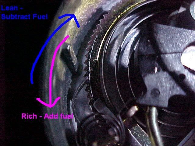 You'll gain mid rpm range power. You'll also gain top rpm range power under a high load (i.e. top gear-top speed runs). Don't be surprised if you rev back to back in park and it's a tad slower from less fuel -> it will be noticeably faster on the street when there is a load on the engine.
__________________
Forum Guidelines:http://www.automotiveforums.com/vbulletin/guidelines.html "What we've got here is a failure to communicate" Last edited by Brian R.; 08-12-2005 at 11:56 PM. |
|
|
|
|
06-27-2005, 09:01 PM
|
#9 | |
|
Resident Chemist
Join Date: Feb 2004
Location: Rockville, Maryland
Posts: 8,586
Thanks: 105
Thanked 157 Times in 157 Posts
|
Re: Tacoma FAQs and Information
BRAKE LININGS
Q: What are the best brake linings for my Tacoma? Are there any things I should watch out for in changing them? A: The Toyota OEM linings are very good and I recommend them for most uses - I use them exclusively. They are quiet, have good life, and don't trash the rotor/drum. Ceramic linings have been recommended to me, but I haven't tried them. Cheap asbestos linings generally sound like Cooter's Hell when you are stopping and should be used only if you and anyone riding in your car are deaf. You should refinish the rotors if there are any grooves worn in the rotors or if there is any side-to-side wobble (runout). Drums always have to be refinished. Also, be careful not to inhale brake dust from the old pads. Don't blow the dust with your lungs or compressed air to clean the brake parts. Clean the old backing plate, rotor, caliper, etc. with a spray brake cleaner. Use a drip pan to catch the run-off. Always use new springs for the drum brakes. Use high temperature brake grease on all pivot points in drum braking systems. Don't get any liquid on the brake linings or they will be garbage. Don't even touch the linings with your fingers. Watch for wetness around the wheel cylinders, particularly inside behind the dust shields. The cylinders have to be honed or replaced if they leak at all. Flush your brake system periodically to get rid of water and contaminents. These lower the boiling point of the brake fluid and can cause brake failure or pitting of the wheel cylinders. Back off the star wheels on the bottom of the drum mechanism to allow the brake linings to clear the ridge created by drug wear. Use two screwdrivers or other bladed tools that fit in the oval opening covered by the rubber boot. Last but not least, after you change your linings, drive your car like your grandmother for a week or two. This finish cures the brake lining material and will give you a much longer brake life. PULSATING BRAKE PEDAL Q:I 've noticed this problem for quite a while. The brake pedal shakes (vibrates) when braking at or above 50 mph. It happens every time i go down a long slope or on highway. The streering wheel shakes a little bit too. It does not happen below 40 mph. I change the brake pads (front) this March and it did not fix the problem. So what can be the problem? Thanks A: Your brake rotor runout is excessive. basically they're warped Q: Then what work needs to be done? Replace the rotors or resurface them? A: You are correct; resurface them if there is enough meat left on them (wherever you take them to be cut will check the thickness first) or replace them with new ones. If there is plenty of pad left, just sand the pads lightly so they will seat better to the new rotor surface How brakes work: http://auto.howstuffworks.com/brake.htm How disc brakes work: http://auto.howstuffworks.com/disc-brake.htm How drum brakes work: http://auto.howstuffworks.com/drum-brake.htm How anti-lock brakes work: http://auto.howstuffworks.com/anti-lock-brake.htm Here are general discussions on the topic: http://www.babcox.com/editorial/ic/ic20316.htm http://www.asbestos-institute.ca/saf...section5d.html http://www.mightyautoparts.com/pdf/articles/tt68.pdf
__________________
Forum Guidelines:http://www.automotiveforums.com/vbulletin/guidelines.html "What we've got here is a failure to communicate" Last edited by Brian R.; 08-13-2005 at 12:00 AM. |
|
|
|
|
06-27-2005, 10:02 PM
|
#10 | |
|
Resident Chemist
Join Date: Feb 2004
Location: Rockville, Maryland
Posts: 8,586
Thanks: 105
Thanked 157 Times in 157 Posts
|
Re: Tacoma FAQs and Information
TIRE SIZE COMPENSATION CALCULATOR
Q: Please tell me how to calculate the speedometer error if I go to different than stock tire diameters. A: Here is a calculator just for that purpose: http://www.miata.net/garage/tirecalc.html
__________________
Forum Guidelines:http://www.automotiveforums.com/vbulletin/guidelines.html "What we've got here is a failure to communicate" Last edited by Brian R.; 08-13-2005 at 12:03 AM. |
|
|
|
|
06-27-2005, 10:31 PM
|
#11 | |
|
Resident Chemist
Join Date: Feb 2004
Location: Rockville, Maryland
Posts: 8,586
Thanks: 105
Thanked 157 Times in 157 Posts
|
Re: Tacoma FAQs and Information
REPROGRAMMING REMOTE ENTRY
http://www.automotiveforums.com/vbul...5&page=1&pp=15 http://www.automotiveforums.com/vbul...ad.php?t=73219 http://www.automotiveforums.com/vbul...d.php?t=383114 http://www.automotiveforums.com/vbul...d.php?t=367962 http://www.automotiveforums.com/vbul...d.php?t=348186 http://www.automotiveforums.com/vbul...d.php?t=360771 http://www.automotiveforums.com/vbul...d.php?t=172063
__________________
Forum Guidelines:http://www.automotiveforums.com/vbulletin/guidelines.html "What we've got here is a failure to communicate" Last edited by Brian R.; 08-13-2005 at 12:03 AM. |
|
|
|
|
06-28-2005, 09:03 AM
|
#12 | |
|
Resident Chemist
Join Date: Feb 2004
Location: Rockville, Maryland
Posts: 8,586
Thanks: 105
Thanked 157 Times in 157 Posts
|
Re: Tacoma FAQs and Information
ECT
Q: What does the button on my console labeled "ECT" do? A: ECT is an abreviation for "Electronically Controlled Transmission". The button has two positions, "POWER" and "NORMAL". When switched to the "POWER" position, the ECM shifts the transmission at higher engine rpm in every gear. It also affects the function of the torque converter lock-up mechanism. For further discussion see the following thread: http://www.automotiveforums.com/vbul...8&page=1&pp=15 With regard to the stiffness of the upshifts, in all of the transmissions, as the throttle angle rises, more pressure is built up. This does not change the maximum pressure exerted during the shift, or while in gear. Thus the shift stiffness is unchanged in either ECT mode. (Thanks to Toysrme for adding the above clarification on shift stiffness.) OVERDRIVE Q: What is the function of the overdrive? Is it a separate unit or actually part of my transmission? What happens when I push the button on the side of my shifter and light the "O/D OFF" indicator? A: The overdrive is the highest (lowest numerically) gear in your transmission, by definition higher geared than 1:1 or direct drive - and it is integral with your transmission. When you push the button on the shifter and light the "O/D OFF" indicator, you prevent your transmission from engaging the O/D gear and it stays in the next highest gear. Preventing OD from engaging is useful when you are in stop and go traffic and never get above 30 mph for any length of time. Then, the only time you engage the O/D gear is when you let off the accelerator - causing the transmission to make an unnecessary upshift when you are slowing down. It is also useful to disengage the O/D when you are in hilly country or towing and find your transmission is not able to stay in the high gear. It is better to maintain the next highest gear by turning off the O/D than to have the transmission searching for the correct gear. How an automatic transmission works: http://auto.howstuffworks.com/automa...ansmission.htm
__________________
Forum Guidelines:http://www.automotiveforums.com/vbulletin/guidelines.html "What we've got here is a failure to communicate" Last edited by Brian R.; 08-13-2005 at 12:04 AM. |
|
|
|
|
06-28-2005, 03:55 PM
|
#13 | |
|
Resident Chemist
Join Date: Feb 2004
Location: Rockville, Maryland
Posts: 8,586
Thanks: 105
Thanked 157 Times in 157 Posts
|
Re: Tacoma FAQs and Information
TSBs: TECH SERVICE BULLETINS
Q: Where can I find Tech Service Bulletins for my Tacoma? A: http://www.alldata.com/tsb/Toyota/index-issue.html http://www.edmunds.com/maintenance/MaintenanceServlet http://www-odi.nhtsa.dot.gov/cars/problems/tsb/ http://www.infotraxx.com/?a_aid=15&a_bid=3 http://www.alldata.com/recalls/
__________________
Forum Guidelines:http://www.automotiveforums.com/vbulletin/guidelines.html "What we've got here is a failure to communicate" Last edited by Brian R.; 08-18-2005 at 10:01 AM. |
|
|
|
|
06-30-2005, 01:34 AM
|
#14 | |
|
Resident Chemist
Join Date: Feb 2004
Location: Rockville, Maryland
Posts: 8,586
Thanks: 105
Thanked 157 Times in 157 Posts
|
Re: Tacoma FAQs and Information
CHECK ENGINE LIGHT IN '98 Tacoma
Q: My '98 Tacoma check engine light has just come on recently. I've never seen it on until now and I don't know why. The car has 148k miles on it, what could be the problem? How can I check the code? Is there a reset button or anything I can do? Any help is appreciated. TIA. A: Your truck is OBDII compliant which means you need a code reader. http://www.iequus.com/assets/manuals/3100E.pdf Q: Can I purchase a reader at any autoshop? How much are they? A: You need an adapter that is specific for Toyota. Most readers will work with the appropriate adapter. I have had trouble finding the right adapter at my local stores. I think online is the best place to buy one. I think prices are $100 on up. One that monitors engine functions is particularly useful - feeds data into computer like notebook or hand-held pc. If you live near an Autozone store, they will check it for free. Q: I went to a Autozone store and they said that they could only do 96 and up. Is that true? A: 1996 and later cars have to be OBDII compliant. Toyota made some of their 1994 and 1995 vehicles OBDII compliant. If your car is, then point it out to him and they should check it. Check your emissions sticker under the hood. It will tell you if your car is OBDII compliant or not.
__________________
Forum Guidelines:http://www.automotiveforums.com/vbulletin/guidelines.html "What we've got here is a failure to communicate" Last edited by Brian R.; 08-13-2005 at 12:08 AM. |
|
|
|
|
06-30-2005, 01:44 AM
|
#15 | |
|
Resident Chemist
Join Date: Feb 2004
Location: Rockville, Maryland
Posts: 8,586
Thanks: 105
Thanked 157 Times in 157 Posts
|
Re: Tacoma FAQs and Information
OBDII DTC CODES
A primer on OBDII DTC codes: http://www.overboost.com/story.asp?id=1286&r=1 Here are a list of generic and Toyota-specific DTC codes from http://www.iequus.com/assets/manuals/3100E.pdf DTC Codes in BOLD have troubleshooting guide at the end of this post. The above document also provided Manufacturer-specific DTC codes for Honda, General Motors, Ford, and Chrysler. DIAGNOSTIC TROUBLE CODE DEFINITIONS The following Diagnostic Trouble Code Definitions lists represent the most complete information currently available. OBD II is an evolving system, and new codes and definitions will be added as the system matures. ALWAYS consult the vehicles service manual for code definitions not included in these lists. The following code definition lists provide both Generic Diagnostic Trouble Code Definitions and Manufacturer-Specific Diagnostic Trouble Code Definitions for the following vehicles: OBD II Powertrain GENERIC (P0XXX) Diagnostic Trouble Codes. OBD II Generic Diagnostic Trouble Codes and their definitions apply to all makes and models of import and domestic vehicles that are OBD II COMPLIANT. OBD II Powertrain MANUFACTURER SPECIFIC (P1XXX) Diagnostic Trouble Codes. OBD II Manufacturer-Specific Diagnostic Trouble Codes and their definitions apply only to vehicles produced by the specific manufacturer (Ford, GM, Toyota etc.). GENERIC OBD II CODE DEFINITIONS P0010 "A" Camshaft Position Actuator Circuit (Bank 1) P0011 "A" Camshaft Position - Timing Over-Advanced or System Performance (Bank 1) P0012 "A" Camshaft Position - Timing Over-Retarded (Bank 1) P0013 "B" Camshaft Position - Actuator Circuit (Bank 1) P0014 "B" Camshaft Position - Timing Over-Advanced or System Performance (Bank 1) P0015 "B" Camshaft Position - Timing Over-Retarded (Bank 1) P0020 "A" Camshaft Position Actuator Circuit (Bank 2) P0021 "A" Camshaft Position - Timing Over-Advanced or System Performance (Bank 2) P0022 "A" Camshaft Position - Timing Over-Retarded (Bank 2) P0023 "B" Camshaft Position - Actuator Circuit (Bank 2) P0024 "B" Camshaft Position - Timing Over-Advanced or System Performance (Bank 2) P0025 "B" Camshaft Position - Timing Over-Retarded (Bank 2) P0030 HO2S Heater Control Circuit (Bank 1 Sensor 1) P0031 HO2S Heater Control Circuit Low (Bank 1 Sensor 1) P0032 HO2S Heater Control Circuit High (Bank 1 Sensor 1) P0033 Turbo Charger Bypass Valve Control Circuit P0034 Turbo Charger Bypass Valve Control Circuit Low P0035 Turbo Charger Bypass Valve Control Circuit High P0036 HO2S Heater Control Circuit (Bank 1 Sensor 2) P0037 HO2S Heater Control Circuit Low (Bank 1 Sensor 2) P0038 HO2S Heater Control Circuit High (Bank 1 Sensor 2) P0042 HO2S Heater Control Circuit (Bank 1 Sensor 3) P0043 HO2S Heater Control Circuit Low (Bank 1 Sensor 3) P0044 HO2S Heater Control Circuit High (Bank 1 Sensor 3) P0050 HO2S Heater Control Circuit (Bank 2 Sensor 1) P0051 HO2S Heater Control Circuit Low (Bank 2 Sensor 1) P0052 HO2S Heater Control Circuit High (Bank 2 Sensor 1) P0056 HO2S Heater Control Circuit (Bank 2 Sensor 2) P0057 HO2S Heater Control Circuit Low (Bank 2 Sensor 2) P0058 HO2S Heater Control Circuit High (Bank 2 Sensor 2) P0062 HO2S Heater Control Circuit (Bank 2 Sensor 3) P0063 HO2S Heater Control Circuit Low (Bank 2 Sensor 3) P0064 HO2S Heater Control Circuit High (Bank 2 Sensor 3) P0065 Air Assisted Injector Control Range/Performance P0066 Air Assisted Injector Control Circuit or Circuit Low P0067 Air Assisted Injector Control Circuit High P0070 Ambient Air Temperature Sensor Circuit P0071 Ambient Air Temperature Sensor Range/Performance P0072 Ambient Air Temperature Sensor Circuit Low Input P0073 Ambient Air Temperature Sensor Circuit High Input P0074 Ambient Air Temperature Sensor Circuit Intermittent P0075 Intake Valve Control Solenoid Circuit (Bank 1) P0076 Intake Valve Control Solenoid Circuit Low (Bank 1) P0077 Intake Valve Control Solenoid Circuit High (Bank 1) P0078 Exhaust Valve Control Solenoid Circuit (Bank 1) P0079 Exhaust Valve Control Solenoid Circuit Low (Bank 1) P0080 Exhaust Valve Control Solenoid Circuit High (Bank 1) P0081 Intake Valve Control Solenoid Circuit (Bank 2) P0082 Intake Valve Control Solenoid Circuit Low (Bank 2) P0083 Intake Valve Control Solenoid Circuit High (Bank 2) P0084 Exhaust Valve Control Solenoid Circuit (Bank 2) P0085 Exhaust Valve Control Solenoid Circuit Low (Bank 2) P0086 Exhaust Valve Control Solenoid Circuit High (Bank 2) P0100 Mass or Volume Air Flow Circuit Malfunction P0101 Mass or Volume Circuit Range Performance Problem P0102 Mass or Volume Circuit Low Input P0103 Mass or Volume Circuit High Input P0104 Mass or Volume Circuit Intermittent P0105 Manifold Absolute Pressure/Barometric Pressure Circuit Malfunction P0106 Manifold Absolute Pressure/Barometric Pressure Circuit Range/Performance Problem P0107 Manifold Absolute Pressure/Barometric Pressure Circuit Low Input P0108 Manifold Absolute Pressure/Barometric Pressure Circuit High Input P0109 Manifold Absolute Pressure/Barometric Pressure Circuit Intermittent P0110 Intake Air Temperature Circuit Malfunction P0111 Intake Air Temperature Circuit Range/Performance Problem P0112 Intake Air Temperature Circuit Low Input P0113 Intake Air Temperature Circuit High Input P0114 Intake Air Temperature Circuit Intermittent P0115 Engine Coolant Temperature Circuit Malfunction P0116 Engine Coolant Temperature Circuit Range/Performance Problem P0117 Engine Coolant Temperature Circuit Low Input P0118 Engine Coolant Temperature Circuit High Input P0119 Engine Coolant Temperature Circuit Intermittent P0120 Throttle/Pedal Position Sensor/Switch A Circuit Malfunction P0121 Throttle/Pedal Position Sensor/Switch A Circuit Range/Performance Problem P0122 Throttle/Pedal Position Sensor/Switch A Circuit Low Input P0123 Throttle/Pedal Position Sensor/Switch A Circuit High Input P0124 Throttle/Pedal Position Sensor/Switch A Circuit Intermittent P0125 Insufficient Coolant Temperature for Closed Loop Fuel Control P0126 Insufficient Coolant Temperature for Stable Operation P0127 Intake Air Temperature Too High P0128 Coolant Thermostat (Coolant Temperature Below Thermostat Regulating Temperature) P0130 O2 Sensor Circuit Malfunction (Bank 1 Sensor 1) P0131 O2 Sensor Circuit Low Voltage (Bank 1 Sensor 1) P0132 O2 Sensor Circuit High Voltage (Bank 1 Sensor 1) P0133 O2 Sensor Circuit Slow Response (Bank 1 Sensor 1) P0134 O2 Sensor Circuit No Activity Detected (Bank 1 Sensor 1) P0135 O2 Sensor Heater Circuit Malfunction (Bank 1 Sensor 1) P0136 O2 Sensor Circuit Malfunction (Bank 1 Sensor 2) P0137 O2 Sensor Circuit Low Voltage (Bank 1 Sensor 2) P0138 O2 Sensor Circuit High Voltage (Bank 1 Sensor 2) P0139 O2 Sensor Circuit Slow Response (Bank 1 Sensor 2) P0140 O2 Sensor Circuit No Activity Detected (Bank 1 Sensor 2) P0141 O2 Sensor Heater Circuit Malfunction (Bank 1 Sensor 2) P0142 O2 Sensor Circuit Malfunction (Bank 1 Sensor 3) P0143 O2 Sensor Circuit Low Voltage (Bank 1 Sensor 3) P0144 O2 Sensor Circuit High Voltage (Bank 1 Sensor 3) P0145 O2 Sensor Circuit Slow Response (Bank 1 Sensor 3) P0146 O2 Sensor Circuit No Activity Detected (Bank 1 Sensor 3) P0147 O2 Sensor Heater Circuit Malfunction (Bank 1 Sensor 3) P0148 Fuel Delivery Error P0149 Fuel Timing Error P0150 O2 Sensor Circuit Malfunction (Bank 2 Sensor 1) P0151 O2 Sensor Circuit Low Voltage (Bank 2 Sensor 1) P0152 O2 Sensor Circuit High Voltage (Bank 2 Sensor 1) P0153 O2 Sensor Circuit Slow Response (Bank 2 Sensor 1) P0154 O2 Sensor Circuit No Activity Detected (Bank 2 Sensor 1) P0155 O2 Sensor Heater Circuit Malfunction (Bank 2 Sensor 1) P0156 O2 Sensor Circuit Malfunction (Bank 2 Sensor 2) P0157 O2 Sensor Circuit Low Voltage (Bank 2 Sensor 2) P0158 O2 Sensor Circuit High Voltage (Bank 2 Sensor 2) P0159 O2 Sensor Circuit Slow Response (Bank 2 Sensor 2) P0160 O2 Sensor Circuit No Activity Detected (Bank 2 Sensor 2) P0161 O2 Sensor Heater Circuit Malfunction (Bank 2 Sensor 2) P0162 O2 Sensor Circuit Malfunction (Bank 2 Sensor 3) P0163 O2 Sensor Circuit Low Voltage (Bank 2 Sensor 3) P0164 O2 Sensor Circuit High Voltage (Bank 2 Sensor 3) P0165 O2 Sensor Circuit Slow Response (Bank 2 Sensor 3) P0166 O2 Sensor Circuit No Activity Detected (Bank 2 Sensor 3) P0167 O2 Sensor Heater Circuit Malfunction (Bank 2 Sensor 3) P0168 Fuel Temperature Too High P0169 Incorrect Fuel Composition P0170 Fuel Trim Malfunction (Bank 1) P0171 System too Lean (Bank 1) P0172 System too Rich (Bank 1) P0173 Fuel Trim Malfunction (Bank 2) P0174 System too Lean (Bank 2) P0175 System too Rich (Bank 2) P0176 Fuel Composition Sensor Circuit Malfunction P0177 Fuel Composition Sensor Circuit Range/Performance P0178 Fuel Composition Sensor Circuit Low Input P0179 Fuel Composition Sensor Circuit High Input P0180 Fuel Temperature Sensor A Circuit Malfunction P0181 Fuel Temperature Sensor A Circuit Range/Performance P0182 Fuel Temperature Sensor A Circuit Low Input P0183 Fuel Temperature Sensor A Circuit High Input P0184 Fuel Temperature Sensor A Circuit Intermittent P0185 Fuel Temperature Sensor B Circuit Malfunction P0186 Fuel Temperature Sensor B Circuit Range/Performance P0187 Fuel Temperature Sensor B Circuit Low Input P0188 Fuel Temperature Sensor B Circuit High Input P0189 Fuel Temperature Sensor B Circuit Intermittent P0190 Fuel Rail Pressure Sensor Circuit Malfunction P0191 Fuel Rail Pressure Sensor Circuit Range/Performance P0192 Fuel Rail Pressure Sensor Circuit Low Input P0193 Fuel Rail Pressure Sensor Circuit High Input P0194 Fuel Rail Pressure Sensor Circuit Intermittent P0195 Engine Oil Temperature Sensor Malfunction P0196 Engine Oil Temperature Sensor Range/Performance P0197 Engine Oil Temperature Sensor Low P0198 Engine Oil Temperature Sensor High P0199 Engine Oil Temperature Sensor Intermittent P0200 Injector Circuit Malfunction P0201 Injector Circuit Malfunction - Cylinder 1 P0202 Injector Circuit Malfunction - Cylinder 2 P0203 Injector Circuit Malfunction - Cylinder 3 P0204 Injector Circuit Malfunction - Cylinder 4 P0205 Injector Circuit Malfunction - Cylinder 5 P0206 Injector Circuit Malfunction - Cylinder 6 P0207 Injector Circuit Malfunction - Cylinder 7 P0208 Injector Circuit Malfunction - Cylinder 8 P0209 Injector Circuit Malfunction - Cylinder 9 P0210 Injector Circuit Malfunction - Cylinder 10 P0211 Injector Circuit Malfunction - Cylinder 11 P0212 Injector Circuit Malfunction - Cylinder 12 P0213 Cold Start Injector 1 Malfunction P0214 Cold Start Injector 2 Malfunction P0215 Engine Shutoff Solenoid Malfunction P0216 Injection Timing Control Circuit Malfunction P0217 Engine Overtemp Condition P0218 Transmission Over Temperature Condition P0219 Engine Overspeed Condition P0220 Throttle/Pedal Position Sensor/Switch B Circuit Malfunction P0221 Throttle/Pedal Position Sensor/Switch B Circuit Range/Performance Problem P0222 Throttle/Pedal Position Sensor/Switch B Circuit Low Input P0223 Throttle/Pedal Position Sensor/Switch B Circuit High Input P0224 Throttle/Pedal Position Sensor/Switch B Circuit Intermittent P0225 Throttle/Pedal Position Sensor/Switch C Circuit Malfunction P0226 Throttle/Pedal Position Sensor/Switch C Circuit Range/Performance Problem P0227 Throttle/Pedal Position Sensor/Switch C Circuit Low Input P0228 Throttle/Pedal Position Sensor/Switch C Circuit High Input P0229 Throttle/Pedal Position Sensor/Switch C Circuit Intermittent P0230 Fuel Pump Primary Circuit Malfunction P0231 Fuel Pump Secondary Circuit Low P0232 Fuel Pump Secondary Circuit High P0233 Fuel Pump Secondary Circuit Intermittent P0234 Engine Overboost Condition P0235 Turbocharger Boost Sensor A Circuit Malfunction P0236 Turbocharger Boost Sensor A Circuit Range/Performance P0237 Turbocharger Boost Sensor A Circuit Low P0238 Turbocharger Boost Sensor A Circuit High P0239 Turbocharger Boost Sensor B Circuit Malfunction P0240 Turbocharger Boost Sensor B Circuit Range/Performance P0241 Turbocharger Boost Sensor B Circuit Low P0242 Turbocharger Boost Sensor B Circuit High P0243 Turbocharger Wastegate Solenoid A Malfunction P0244 Turbocharger Wastegate Solenoid A Range/Performance P0245 Turbocharger Wastegate Solenoid A Low P0246 Turbocharger Wastegate Solenoid A High P0247 Turbocharger Wastegate Solenoid B Malfunction P0248 Turbocharger Wastegate Solenoid B Range/Performance P0249 Turbocharger Wastegate Solenoid B Low P0250 Turbocharger Wastegate Solenoid B High P0251 Injection Pump A Rotor/Cam Malfunction P0252 Injection Pump A Rotor/Cam Range/Performance P0253 Injection Pump A Rotor/Cam Low P0254 Injection Pump A Rotor/Cam High P0255 Injection Pump A Rotor/Cam Intermitted P0256 Injection Pump B Rotor/Cam Malfunction P0257 Injection Pump B Rotor/Cam Range/Performance P0258 Injection Pump B Rotor/Cam Low P0259 Injection Pump B Rotor/Cam High P0260 Injection Pump B Rotor/Cam Intermitted P0261 Cylinder 1 Injector Circuit Low P0262 Cylinder 1 Injector Circuit High P0263 Cylinder 1 Contribution/Balance Fault P0264 Cylinder 2 Injector Circuit Low P0265 Cylinder 2 Injector Circuit High P0266 Cylinder 2 Contribution/Balance Fault P0267 Cylinder 3 Injector Circuit Low P0268 Cylinder 3 Injector Circuit High P0269 Cylinder 3 Contribution/Balance Fault P0270 Cylinder 4 Injector Circuit Low P0271 Cylinder 4 Injector Circuit High P0272 Cylinder 4 Contribution/Balance Fault P0273 Cylinder 5 Injector Circuit Low P0274 Cylinder 5 Injector Circuit High P0275 Cylinder 5 Contribution/Balance Fault P0276 Cylinder 6 Injector Circuit Low P0277 Cylinder 6 Injector Circuit High P0278 Cylinder 6 Contribution/Balance Fault P0279 Cylinder 7 Injector Circuit Low P0280 Cylinder 7 Injector Circuit High P0281 Cylinder 7 Contribution/Balance Fault P0282 Cylinder 8 Injector Circuit Low P0283 Cylinder 8 Injector Circuit High P0284 Cylinder 8 Contribution/Balance Fault P0285 Cylinder 9 Injector Circuit Low P0286 Cylinder 9 Injector Circuit High P0287 Cylinder 9 Contribution/Balance Fault P0288 Cylinder 10 Injector Circuit Low P0289 Cylinder 10 Injector Circuit High P0290 Cylinder 10 Contribution/Balance Fault P0291 Cylinder 11 Injector Circuit Low P0292 Cylinder 11 Injector Circuit High P0293 Cylinder 11 Contribution/Balance Fault P0294 Cylinder 12 Injector Circuit Low P0295 Cylinder 12 Injector Circuit High P0296 Cylinder 12 Contribution/Balance Fault P0298 Engine Oil Over Temperature P0300 Random/Multiple Cylinder Misfire Detected P0301 Cylinder 1 Misfire Detected P0302 Cylinder 2 Misfire Detected P0303 Cylinder 3 Misfire Detected P0304 Cylinder 4 Misfire Detected P0305 Cylinder 5 Misfire Detected P0306 Cylinder 6 Misfire Detected P0307 Cylinder 7 Misfire Detected P0308 Cylinder 8 Misfire Detected P0309 Cylinder 9 Misfire Detected P0310 Cylinder 10 Misfire Detected P0311 Cylinder 11 Misfire Detected P0312 Cylinder 12 Misfire Detected P0313 Misfire Detected with Low Fuel P0314 Single Cylinder Misfire (Cylinder not specified) P0320 Ignition/Distributor Engine Speed Input Circuit Malfunction P0321 Ignition/Distributor Engine Speed Input Circuit Range/Performance P0322 Ignition/Distributor Engine Speed Input Circuit No Signal P0323 Ignition/Distributor Engine Speed Input Circuit Intermittent P0324 Knock Control System Error P0325 Knock Sensor 1 Circuit Malfunction (Bank 1 or Single Sensor) P0326 Knock Sensor 1 Circuit Range/Performance (Bank 1 or Single Sensor) P0327 Knock Sensor 1 Circuit Low Input (Bank 1 or Single Sensor) P0328 Knock Sensor 1 Circuit High Input (Bank 1 or Single Sensor) P0329 Knock Sensor 1 Circuit Intermittent (Bank 1 or Single Sensor) P0330 Knock Sensor 2 Circuit Malfunction (Bank 2) P0331 Knock Sensor 2 Circuit Range/Performance (Bank 2) P0332 Knock Sensor 2 Circuit Low Input (Bank 2) P0333 Knock Sensor 2 Circuit High Input (Bank 2) P0334 Knock Sensor 2 Circuit Intermittent (Bank 2) P0335 Crankshaft Position Sensor A Circuit Malfunction P0336 Crankshaft Position Sensor A Circuit Range/Performance P0337 Crankshaft Position Sensor A Circuit Low Input P0338 Crankshaft Position Sensor A Circuit High Input P0339 Crankshaft Position Sensor A Circuit Intermittent P0340 Camshaft Position Sensor Circuit Malfunction P0341 Camshaft Position Sensor Circuit Range/Performance P0342 Camshaft Position Sensor Circuit Low Input P0343 Camshaft Position Sensor Circuit High Input P0344 Camshaft Position Sensor Circuit Intermittent P0345 Camshaft Position Sensor "A" Circuit (Bank 2) P0346 Camshaft Position Sensor "A" Circuit Range/Performance (Bank 2) P0347 Camshaft Position Sensor "A" Circuit Low Input (Bank 2) P0348 Camshaft Position Sensor "A" Circuit High Input (Bank 2) P0349 Camshaft Position Sensor "A" Circuit Intermittent (Bank 2) P0350 Ignition Coil Primary/Secondary Circuit Malfunction P0351 Ignition Coil A Primary/Secondary Circuit Malfunction P0352 Ignition Coil B Primary/Secondary Circuit Malfunction P0353 Ignition Coil C Primary/Secondary Circuit Malfunction P0354 Ignition Coil D Primary/Secondary Circuit Malfunction P0355 Ignition Coil E Primary/Secondary Circuit Malfunction P0356 Ignition Coil F Primary/Secondary Circuit Malfunction P0357 Ignition Coil G Primary/Secondary Circuit Malfunction P0358 Ignition Coil H Primary/Secondary Circuit Malfunction P0359 Ignition Coil I Primary/Secondary Circuit Malfunction P0360 Ignition Coil J Primary/Secondary Circuit Malfunction P0361 Ignition Coil K Primary/Secondary Circuit Malfunction P0362 Ignition Coil L Primary/Secondary Circuit Malfunction P0365 Camshaft Position Sensor "B" Circuit (Bank 1) P0366 Camshaft Position Sensor "B" Circuit Range/Performance (Bank 1) P0367 Camshaft Position Sensor "B" Circuit Low Input (Bank 1) P0368 Camshaft Position Sensor "B" Circuit High Input (Bank 1) P0369 Camshaft Position Sensor "B" Circuit Intermittent (Bank 1) P0370 Timing Reference High Resolution Signal A Malfunction P0371 Timing Reference High Resolution Signal A Too Many Pulses P0372 Timing Reference High Resolution Signal A Too Few Pulses P0373 Timing Reference High Resolution Signal A Intermittent/ Erratic Pulses P0374 Timing Reference High Resolution Signal A No Pulses P0375 Timing Reference High Resolution Signal B Malfunction P0376 Timing Reference High Resolution Signal B Too Many Pulses P0377 Timing Reference High Resolution Signal B Too Few Pulses P0378 Timing Reference High Resolution Signal B Intermittent/ Erratic Pulses P0379 Timing Reference High Resolution Signal B No Pulses P0380 Glow Plug/Heater Circuit Malfunction P0381 Glow Plug/Heater Indicator Circuit Malfunction P0382 Glow Plug/Heater Circuit "B" Malfunction P0385 Crankshaft Position Sensor B Circuit Malfunction P0386 Crankshaft Position Sensor B Circuit Range/Performance P0387 Crankshaft Position Sensor B Circuit Low Input P0388 Crankshaft Position Sensor B Circuit High Input P0389 Crankshaft Position Sensor B Circuit Intermittent P0390 Camshaft Position Sensor "B" Circuit (Bank 2) P0391 Camshaft Position Sensor "B" Circuit Range/Performance (Bank 2) P0392 Camshaft Position Sensor "B" Circuit Low Input (Bank 2) P0393 Camshaft Position Sensor "B" Circuit High Input (Bank 2) P0394 Camshaft Position Sensor "B" Circuit Intermittent (Bank 2) P0400 Exhaust Gas Recirculation Flow Malfunction P0401 Exhaust Gas Recirculation Flow Insufficient Detected P0402 Exhaust Gas Recirculation Flow Excessive Detected P0403 Exhaust Gas Recirculation Circuit Malfunction P0404 Exhaust Gas Recirculation Circuit Range/Performance P0405 Exhaust Gas Recirculation Sensor A Circuit Low P0406 Exhaust Gas Recirculation Sensor A Circuit High P0407 Exhaust Gas Recirculation Sensor B Circuit Low P0408 Exhaust Gas Recirculation Sensor B Circuit High P0409 Exhaust Gas Recirculation Sensor "A" Circuit P0410 Secondary Air Injection System Malfunction P0411 Secondary Air Injection System Incorrect Flow Detected P0412 Secondary Air Injection System Switching Valve A Circuit Malfunction P0413 Secondary Air Injection System Switching Valve A Circuit Open P0414 Secondary Air Injection System Switching Valve A Circuit Shorted P0415 Secondary Air Injection System Switching Valve B Circuit Malfunction P0416 Secondary Air Injection System Switching Valve B Circuit Open P0417 Secondary Air Injection System Switching Valve B Circuit Shorted P0418 Secondary Air Injection System Relay "A" Circuit Malfunction P0419 Secondary Air Injection System Relay "B" Circuit Malfunction P0420 Catalyst System Efficiency Below Threshold (Bank 1) P0421 Warm Up Catalyst Efficiency Below Threshold (Bank 1) P0422 Main Catalyst Efficiency Below Threshold (Bank 1) P0423 Heated Catalyst Efficiency Below Threshold (Bank 1) P0424 Heated Catalyst Temperature Below Threshold (Bank 1) P0425 Catalyst Temperature Sensor (Bank 1) P0426 Catalyst Temperature Sensor Range/Performance (Bank 1) P0427 Catalyst Temperature Sensor Low Input (Bank 1) P0428 Catalyst Temperature Sensor High Input (Bank 1) P0429 Catalyst Heater Control Circuit (Bank 1) P0430 Catalyst System Efficiency Below Threshold (Bank 2) P0431 Warm Up Catalyst Efficiency Below Threshold (Bank 2) P0432 Main Catalyst Efficiency Below Threshold (Bank 2) P0433 Heated Catalyst Efficiency Below Threshold (Bank 2) P0434 Heated Catalyst Temperature Below Threshold (Bank 2) P0435 Catalyst Temperature Sensor (Bank 2) P0436 Catalyst Temperature Sensor Range/Performance (Bank 2) P0437 Catalyst Temperature Sensor Low Input (Bank 2) P0438 Catalyst Temperature Sensor High Input (Bank 2) P0439 Catalyst Heater Control Circuit (Bank 2) P0440 Evaporative Emission Control System Malfunction P0441 Evaporative Emission Control System Incorrect Purge Flow P0442 Evaporative Emission Control System Leak Detected (small leak) P0443 Evaporative Emission Control System Purge Control Valve Circuit Malfunction P0444 Evaporative Emission Control System Purge Control Valve Circuit Open P0445 Evaporative Emission Control System Purge Control Valve Circuit Shorted P0446 Evaporative Emission Control System Vent Control Circuit Malfunction P0447 Evaporative Emission Control System Vent Control Circuit Open P0448 Evaporative Emission Control System Vent Control Circuit Shorted P0449 Evaporative Emission Control System Vent Valve/Solenoid Circuit Malfunction P0450 Evaporative Emission Control System Pressure Sensor Malfunction P0451 Evaporative Emission Control System Pressure Sensor Range/Performance P0452 Evaporative Emission Control System Pressure Sensor Low Input P0453 Evaporative Emission Control System Pressure Sensor High Input P0454 Evaporative Emission Control System Pressure Sensor Intermittent P0455 Evaporative Emission Control System Leak Detected (gross leak) P0456 Evaporative Emission Control System Leak Detected (very small leak) P0457 Evaporative Emission Control System Leak Detected (fuel cap loose/off) P0460 Fuel Level Sensor Circuit Malfunction P0461 Fuel Level Sensor Circuit Range/Performance P0462 Fuel Level Sensor Circuit Low Input P0463 Fuel Level Sensor Circuit High Input P0464 Fuel Level Sensor Circuit Intermittent P0465 Purge Flow Sensor Circuit Malfunction P0466 Purge Flow Sensor Circuit Range/Performance P0467 Purge Flow Sensor Circuit Low Input P0468 Purge Flow Sensor Circuit High Input P0469 Purge Flow Sensor Circuit Intermittent P0470 Exhaust Pressure Sensor Malfunction P0471 Exhaust Pressure Sensor Range/Performance P0472 Exhaust Pressure Sensor Low P0473 Exhaust Pressure Sensor High P0474 Exhaust Pressure Sensor Intermittent P0475 Exhaust Pressure Control Valve Malfunction P0476 Exhaust Pressure Control Valve Range/Performance P0477 Exhaust Pressure Control Valve Low P0478 Exhaust Pressure Control Valve High P0479 Exhaust Pressure Control Valve Intermittent P0480 Cooling Fan 1 Control Circuit Malfunction P0481 Cooling Fan 2 Control Circuit Malfunction P0482 Cooling Fan 3 Control Circuit Malfunction P0483 Cooling Fan Rationality Check Malfunction P0484 Cooling Fan Circuit Over Current P0485 Cooling Fan Power/Ground Circuit Malfunction P0486 Exhaust Gas Recirculation Sensor "B" Circuit P0487 Exhaust Gas Recirculation Throttle Position Control Circuit P0488 Exhaust Gas Recirculation Throttle Position Control Range/Performance P0491 Secondary Air Injection System (Bank 1) P0492 Secondary Air Injection System (Bank 2) P0500 Vehicle Speed Sensor Malfunction P0501 Vehicle Speed Sensor Range/Performance P0502 Vehicle Speed Sensor Circuit Low Input P0503 Vehicle Speed Sensor Intermittent/Erratic/High P0505 Idle Control System Malfunction P0506 Idle Control System RPM Lower Than Expected P0507 Idle Control System RPM Higher Than Expected P0508 Idle Control System Circuit Low P0509 Idle Control System Circuit High P0510 Closed Throttle Position Switch Malfunction P0512 Starter Request Circuit P0513 Incorrect Immobilizer Key ("Immobilizer" pending SAE J1930 approval) P0515 Battery Temperature Sensor Circuit P0516 Battery Temperature Sensor Circuit Low P0517 Battery Temperature Sensor Circuit High P0520 Engine Oil Pressure/Switch Circuit Malfunction P0521 Engine Oil Pressure/Switch Range/Performance P0522 Engine Oil Pressure/Switch Low Voltage P0523 Engine Oil Pressure/Switch High Voltage P0524 Engine Oil Pressure Too Low P0530 A/C Refrigerant Pressure Sensor Circuit Malfunction P0531 A/C Refrigerant Pressure Sensor Circuit Range/Performance P0532 A/C Refrigerant Pressure Sensor Circuit Low Input P0533 A/C Refrigerant Pressure Sensor Circuit High Input P0534 Air Conditioner Refrigerant Charge Loss P0540 Intake Air Heater Circuit P0541 Intake Air Heater Circuit Low P0542 Intake Air Heater Circuit High P0544 Exhaust Gas Temperature Sensor Circuit (Bank 1) P0545 Exhaust Gas Temperature Sensor Circuit Low (Bank 1) P0546 Exhaust Gas Temperature Sensor Circuit High (Bank 1) P0547 Exhaust Gas Temperature Sensor Circuit (Bank 2) P0548 Exhaust Gas Temperature Sensor Circuit Low (Bank 2) P0549 Exhaust Gas Temperature Sensor Circuit High (Bank 2) P0550 Power Steering Pressure Sensor Circuit Malfunction P0551 Power Steering Pressure Sensor Circuit Range/Performance P0552 Power Steering Pressure Sensor Circuit Low Input P0553 Power Steering Pressure Sensor Circuit High Input P0554 Power Steering Pressure Sensor Circuit Intermittent P0560 System Voltage Malfunction P0561 System Voltage Unstable P0562 System Voltage Low P0563 System Voltage High P0564 Cruise Control Multi-Function Input Signal P0565 Cruise Control On Signal Malfunction P0566 Cruise Control Off Signal Malfunction P0567 Cruise Control Resume Signal Malfunction P0568 Cruise Control Set Signal Malfunction P0569 Cruise Control Coast Signal Malfunction P0570 Cruise Control Accel Signal Malfunction P0571 Cruise Control/Brake Switch A Circuit Malfunction P0572 Cruise Control/Brake Switch A Circuit Low P0573 Cruise Control/Brake Switch A Circuit High P0574 Cruise Control System - Vehicle Speed Too High P0575 Cruise Control Input Circuit P0576 Cruise Control Input Circuit Low P0577 Cruise Control Input Circuit High P0578-P0580 Reserved for Cruise Control Codes P0600 Serial Communication Link Malfunction P0601 Internal Control Module Memory Check Sum Error P0602 Control Module Programming Error P0603 Internal Control Module Keep Alive Memory (KAM) Error P0604 Internal Control Module Random Access Memory (RAM) Error P0605 Internal Control Module Read Only Memory (ROM) Error P0606 PCM Processor Fault P0607 Control Module Performance P0608 Control Module VSS Output "A" Malfunction P0609 Control Module VSS Output "B" Malfunction P0610 Control Module Vehicle Options Error P0615 Starter Relay Circuit P0616 Starter Relay Circuit Low P0617 Starter Relay Circuit High P0618 Alternative Fuel Control Module KAM Error P0619 Alternative Fuel Control Module RAM/ROM Error P0620 Generator Control Circuit Malfunction P0621 Generator Lamp "L" Control Circuit Malfunction P0622 Generator Field "F" Control Circuit Malfunction P0623 Generator Lamp Control Circuit P0624 Fuel Cap Lamp Control Circuit P0630 VIN Not Programmed or Mismatch - ECM/PCM P0631 VIN Not Programmed or Mismatch - TCM P0635 Power Steering Control Circuit P0636 Power Steering Control Circuit Low P0637 Power Steering Control Circuit High P0638 Throttle Actuator Control Range/Performance (Bank 1) P0639 Throttle Actuator Control Range/Performance (Bank 2) P0640 Intake Air Heater Control Circuit P0645 A/C Clutch Relay Control Circuit P0646 A/C Clutch Relay Control Circuit Low P0647 A/C Clutch Relay Control Circuit High P0648 Immobilizer Lamp Control Circuit ("Immobilizer" pending SAE J1930 approval) P0649 Speed Control Lamp Control Circuit P0650 Malfunction Indicator Lamp (MIL) Control Circuit Malfunction P0654 Engine RPM Output Circuit Malfunction P0655 Engine Hot Lamp Output Control Circuit Malfunction P0656 Fuel Level Output Circuit Malfunction P0660 Intake Manifold Tuning Valve Control Circuit (Bank 1) P0661 Intake Manifold Tuning Valve Control Circuit Low (Bank 1) P0662 Intake Manifold Tuning Valve Control Circuit High (Bank 1) P0663 Intake Manifold Tuning Valve Control Circuit (Bank 2) P0664 Intake Manifold Tuning Valve Control Circuit Low (Bank 2) P0665 Intake Manifold Tuning Valve Control Circuit High (Bank 2) P0700 Transmission Control System Malfunction P0701 Transmission Control System Range/Performance P0702 Transmission Control System Electrical P0703 Torque Converter/Brake Switch B Circuit Malfunction P0704 Clutch Switch Input Circuit Malfunction P0705 Transmission Range Sensor Circuit Malfunction (PRNDL Input) P0706 Transmission Range Sensor Circuit Range/Performance P0707 Transmission Range Sensor Circuit Low Input P0708 Transmission Range Sensor Circuit High Input P0709 Transmission Range Sensor Circuit Intermittent P0710 Transmission Fluid Temperature Sensor Circuit Malfunction P0711 Transmission Fluid Temperature Sensor Circuit Range/Performance P0712 Transmission Fluid Temperature Sensor Circuit Low Input P0713 Transmission Fluid Temperature Sensor Circuit High Input P0714 Transmission Fluid Temperature Sensor Circuit Intermittent P0715 Input/Turbine Speed Sensor Circuit Malfunction P0716 Input/Turbine Speed Sensor Circuit Range/Performance P0717 Input/Turbine Speed Sensor Circuit No Signal P0718 Input/Turbine Speed Sensor Circuit Intermittent P0719 Torque Converter/Brake Switch B Circuit Low P0720 Output Speed Sensor Circuit Malfunction P0721 Output Speed Sensor Circuit Range/Performance P0722 Output Speed Sensor Circuit No Signal P0723 Output Speed Sensor Circuit Intermittent P0724 Torque Converter/Brake Switch B Circuit High P0725 Engine Speed Input Circuit Malfunction P0726 Engine Speed Input Circuit Range/Performance P0727 Engine Speed Input Circuit No Signal P0728 Engine Speed Input Circuit Intermittent P0730 Incorrect Gear Ratio P0731 Gear 1 Incorrect Ratio P0732 Gear 2 Incorrect Ratio P0733 Gear 3 Incorrect Ratio P0734 Gear 4 Incorrect Ratio P0735 Gear 5 Incorrect Ratio P0736 Reverse Incorrect Ratio P0737 TCM Engine Speed Output Circuit P0738 TCM Engine Speed Output Circuit Low P0739 TCM Engine Speed Output Circuit High P0740 Torque Converter Clutch Circuit Malfunction P0741 Torque Converter Clutch Circuit Performance or Stuck Off P0742 Torque Converter Clutch Circuit Stuck On P0743 Torque Converter Clutch Circuit Electrical P0744 Torque Converter Clutch Circuit Intermittent P0745 Pressure Control Solenoid Malfunction P0746 Pressure Control Solenoid Performance or Stuck Off P0747 Pressure Control Solenoid Stuck On P0748 Pressure Control Solenoid Electrical P0749 Pressure Control Solenoid Intermittent P0750 Shift Solenoid A Malfunction P0751 Shift Solenoid A Performance or Stuck Off P0752 Shift Solenoid A Stuck On P0753 Shift Solenoid A Electrical P0754 Shift Solenoid A Intermittent P0755 Shift Solenoid B Malfunction P0756 Shift Solenoid B Performance or Stuck Off P0757 Shift Solenoid B Stuck On P0758 Shift Solenoid B Electrical P0759 Shift Solenoid B Intermittent P0760 Shift Solenoid C Malfunction P0761 Shift Solenoid C Performance or Stuck Off P0762 Shift Solenoid C Stuck On P0763 Shift Solenoid C Electrical P0764 Shift Solenoid C Intermittent P0765 Shift Solenoid D Malfunction P0766 Shift Solenoid D Performance or Stuck Off P0767 Shift Solenoid D Stuck On P0768 Shift Solenoid D Electrical P0769 Shift Solenoid D Intermittent P0770 Shift Solenoid E Malfunction P0771 Shift Solenoid E Performance or Stuck Off P0772 Shift Solenoid E Stuck On P0773 Shift Solenoid E Electrical P0774 Shift Solenoid E Intermittent P0775 Pressure Control Solenoid "B" P0776 Pressure Control Solenoid "B" Performance or Stuck Off P0777 Pressure Control Solenoid "B" Stuck On P0778 Pressure Control Solenoid "B" Electrical P0779 Pressure Control Solenoid "B" Intermittent P0780 Shift Malfunction P0781 1-2 Shift Malfunction P0782 2-3 Shift Malfunction P0783 3-4 Shift Malfunction P0784 4-5 Shift Malfunction P0785 Shift/Timing Solenoid Malfunction P0786 Shift/Timing Solenoid Range/Performance P0787 Shift/Timing Solenoid Low P0788 Shift/Timing Solenoid High P0789 Shift/Timing Solenoid Intermittent P0790 Normal/Performance Switch Circuit Malfunction P0791 Intermediate Shaft Speed Sensor Circuit P0792 Intermediate Shaft Speed Sensor Circuit Range/Performance P0793 Intermediate Shaft Speed Sensor Circuit No Signal P0794 Intermediate Shaft Speed Sensor Circuit Intermittent P0795 Pressure Control Solenoid "C" P0796 Pressure Control Solenoid "C" Performance or Stuck Off P0797 Pressure Control Solenoid "C" Stuck On P0798 Pressure Control Solenoid "C" Electrical P0799 Pressure Control Solenoid "C" Intermittent P0801 Reverse Inhibit Control Circuit Malfunction P0803 1-4 Upshift (Skip Shift) Solenoid Control Circuit Malfunction P0804 1-4 Upshift (Skip Shift) Lamp Control Circuit Malfunction P0805 Clutch Position Sensor Circuit P0806 Clutch Position Sensor Circuit Range/Performance P0807 Clutch Position Sensor Circuit Low P0808 Clutch Position Sensor Circuit High P0809 Clutch Position Sensor Circuit Intermittent P0810 Clutch Position Control Error P0811 Excessive Clutch Slippage P0812 Reverse Input Circuit P0813 Reverse Output Circuit P0814 Transmission Range Display Circuit P0815 Upshift Switch Circuit P0816 Downshift Switch Circuit P0817 Starter Disable Circuit P0818 Driveline Disconnect Switch Input Circuit P0820 Gear Lever X-Y Position Sensor Circuit P0821 Gear Lever X Position Circuit P0822 Gear Lever Y Position Circuit P0823 Gear Lever X Position Circuit Intermittent P0824 Gear Lever Y Position Circuit Intermittent P0825 Gear Lever Push-Pull Switch (Shift Anticipate) P0830 Clutch Pedal Switch "A" Circuit P0831 Clutch Pedal Switch "A" Circuit Low P0832 Clutch Pedal Switch "A" Circuit High P0833 Clutch Pedal Switch "B" Circuit P0834 Clutch Pedal Switch "B" Circuit Low P0835 Clutch Pedal Switch "B" Circuit High P0836 Four Wheel Drive (4WD) Switch Circuit P0837 Four Wheel Drive (4WD) Switch Circuit Range/Performance P0838 Four Wheel Drive (4WD) Switch Circuit Low P0839 Four Wheel Drive (4WD) Switch Circuit High P0840 Transmission Fluid Pressure Sensor/Switch "A" Circuit P0841 Transmission Fluid Pressure Sensor/Switch "A" Circuit Range/Performance P0842 Transmission Fluid Pressure Sensor/Switch "A" Circuit Low P0843 Transmission Fluid Pressure Sensor/Switch "A" Circuit High P0844 Transmission Fluid Pressure Sensor/Switch "A" Circuit Intermittent P0845 Transmission Fluid Pressure Sensor/Switch "B" Circuit P0846 Transmission Fluid Pressure Sensor/Switch "B" Circuit Range/Performance P0847 Transmission Fluid Pressure Sensor/Switch "B" Circuit Low P0848 Transmission Fluid Pressure Sensor/Switch "B" Circuit High P0849 Transmission Fluid Pressure Sensor/Switch "B" Circuit Intermittent TOYOTA-SPECIFIC OBD II CODE DEFINITIONS P1100 BARO Sensor Circuit malfunction P1120 Accelerator Pedal Position Sensor Circuit Malfunction P1121 Accelerator Pedal Position Sensor Range/Performance Problem P1125 Throttle Control Motor Circuit Malfunction P1126 Magnetic Clutch Circuit Malfunction P1127 ETCS Actuator Power Source Circuit Malfunction P1128 Throttle Control Motor Lock Malfunction P1129 Electric Throttle Control System Malfunction P1130 Air-Fuel Sensor Circuit Range/Performance P1133 Air-Fuel Sensor Circuit Response Malfunction P1135 Air-Fuel Sensor Heater Circuit Response Malfunction P1150 A/F Sensor Circuit Range/Performance Malfunction P1153 A./F Sensor Circuit Response Malfunction P1155 A/F Sensor Heater Circuit Malfunction P1200 Fuel Pump Relay Circuit Malfunction P1300 Igniter Circuit Malfunction No. 1 P1305 Igniter Circuit Malfunction No. 2 (1998-2000 Land Cruiser, 2000 Celica & Tundra) P1310 Igniter Circuit Malfunction No. 2 (Except 1998-2000 Land Cruiser, 2000 Celica & Tundra) P1310 Igniter Circuit Malfunction No. 3 (1998-2000 Land Cruiser, 2000 Celica & Tundra) P1315 Igniter Circuit Malfunction No. 4 (1998-2000 Land Cruiser, 2000 Celica & Tundra) P1320 Igniter Circuit Malfunction No. 5 (1998-2000 Land Cruiser & 2000 Tundra) P1325 Igniter Circuit Malfunction No. 6 (1998-2000 Land Cruiser & 2000 Tundra) P1330 Igniter Circuit Malfunction No. 7 (1998-2000 Land Cruiser & 2000 Tundra) P1335 No CKP Sensor Signal Engine Running P1340 Igniter Circuit Malfunction No. 8 (1998-2000 Land Cruiser & 2000 Tundra) P1346 VVT Sensor /Camshaft Position Sensor Circuit Range/Performance Problem (Bank 1) P1349 VVT System Malfunction P1400 Sub-Throttle Position Sensor Malfunction P1401 Sub-Throttle Position Sensor Range/Performance Problem P1405 Turbo Pressure Sensor Circuit Malfunction P1406 Turbo Pressure Sensor Range/Performance Problem P1410 EGR Valve Position Sensor Circuit Malfunction P1411 EGR Valve Position Sensor Circuit Ranger/Performance P1500 Starter Signal Circuit Malfunction P1510 Boost Pressure Control Circuit Malfunction P1511 Boost Pressure Low Malfunction P1512 Boost Pressure High Malfunction P1520 Stop Lamp Switch Signal Malfunction P1565 Cruise Control Main Switch Circuit Malfunction P1600 ECM BATT Malfunction P1605 Knock Control CPU Malfunction P1630 Traction Control System Malfunction P1633 ECM Malfunction ECTS Circuit P1645 Body ECU Malfunction P1652 IACV Control Circuit Malfunction P1656 OCV Circuit Malfunction P1658 Waste Gate Valve Control Circuit Malfunction P1661 EGR Circuit Malfunction P1662 EGR By-Pass Valve Control Circuit Malfunction P1690 OCV Circuit Malfunction P1692 OCV Open Malfunction P1693 OCV Closed Malfunction P1780 PNP Switch Malfunction **************************** TROUBLESHOOTING SOME COMMON CODES P0325 No knock sensor 1 signal to ECM with engine speed 2,000 rpm or more. Possible Problems Open or short in knock sensor 1 circuit <= Most likely problem. Check sensor connector for good connection and check wire for damage. Wire is easily damaged when head is removed or similar repair work has been accomplished. Sensor can be tested with ohmmeter. There should be no continuity between the sensor terminal and the sensor body. Replace if there is continuity. Knock sensor 1 loosness - tighten sensor ECM P0330 No knock sensor 2 signal to ECM with engine speed 2,000 rpm or more. Possible Problems Open or short in knock sensor 2 circuit <= Most likely problem.Check sensor connector for good connection and check wire for damage. Wire is easily damaged when head is removed or similar repair work has been accomplished. Sensor can be tested with ohmmeter. There should be no continuity between the sensor terminal and the sensor body. Replace if there is continuity. Knock sensor 2 loosness - tighten sensor ECM P0401 After the engine is warmed up, the intake manifold absolute pressure is larger than the value calculated by the ECM while the EGR system is ON (2 trip detection logic). Possible Problems EGR valve stuck closed <= Most common Clean EGR valve EGR Vacuum Switching Valve (VSV) Open or short in VSV circuit for EGR EGR valve position sensor open or short circuit Vacuum or EGR hose disconnected EGR valve position sensor Manifold absolute pressure sensor malfunction ECM P0402 After the engine is warmed up, conditions (a) and (b) continue. (a) The intake manifold absolute pressure is larger than the value calculated by the ECM while the EGR system is ON. (b) Misfiring is detected during idling (2 trip detection logic). Possible Problems EGR valve stuck open <= Most common Clean EGR valve Vacuum or EGR hose is connected to wrong post Manifold absolute pressure sensor malfunction ECM P0440 The fuel tank pressure is atmospheric pressure after the vehicle is driven for 20 min (2 trip detection logic). Possible Problems Fuel tank cap incorrectly installed <= Most common Fuel tank cap cracked or damaged (Toyota part only) Bad vapor pressure sensor/circuit Vacuum hose cracked, holed, blocked, damaged or disconnected Hose or tube cracked, holed, damaged, or loose Fuel tank/filler neck cracked, holed, or damaged Charcoal canister cracked, holed, or damaged (collision) In above description, check hoses between vapor pressur sensor and VSV for vapor pressure sensor and charcoal canister. Also, hose between charcoal canister and fuel tank. P0441 and/or P0446 Possible Problems Open or short in VSV circuit for vapor pressure sensor VSV for vapor pressure sensor Open or short in vapor pressure sensor circuit Vapor pressure sensor Open or short in VSV circuit for EVAP VSV for EVAP Vacuum hose cracks, hole, blocked, damaged or disconnected Charcoal canister cracks, hole, or damaged (P0446 is not normally associated with a loose or non-sealing gas cap. A loose or non-sealing gas cap triggers P0440) 1. Check the VSV connector for EVAP, VSV connector for vapor pressure sensor and vapor pressure sensor connector for looseness and disconnection 2. Check the vacuum hose between intake manifold and VSV for EVAP, VSV for EVAP and charcoal canister, charcoal canister and VSV for vapor pressure sensor, and VSV for vapor pressure sensor and vapor pressure sensor. Check these hoses for correct connection, looseness, cracks, holes, damage, and blockage. 3. Check voltage between terminals VC and E2 of ECM connector (4.5-5.5 V). (replace ECM if faulty) 4. Check voltages between terminals PTNK and E2 of ECM connector while applying vacuum to vapor pressure sensor (2.9-3.7 V). If faulty, check for open and short in harness and connector between vapor pressure sensor and ECM. If ok at this point, replace vapor pressure sensor. If voltage above is ok, Check VSV for EVAP. When ECM terminal EVP is grounded (ignition "ON"), Air should flow in pipe E (inboard on tube) on VSV and out F (outboard on tube) on VSV (Don't use high pressure air for this test). When EVP is not grounded, air does not flow in E and out F. 5. Check operation of VSV for EVAP. Remove VSV from engine. Check that there is continuity between the two terminals (30-34 ohms). If there is no continuity, replace VSV for EVAP. Check that there is no continuity between either terminal and body. If there is continuity, replace VSV for EVAP. Check that air does not flow from inner port (E) to outboard port (F). Check that air flows from port E to F when you apply battery voltage across terminals. If no air flows, replace VSV for EVAP. 6. Check the vacuum hose between intake manifold and VSV for EVAP, and VSV for EVAP and charcoal canister. Check as above. 7. Check for open or short in harness and connector between EFI main-relay and VSV for EVAP and ECM. If faulty, repair or replace harness or connector. If ok, check and replace ECM. 8. Check VSV for vapor pressure sensor. When ECM terminal TPC is grounded (ignition "ON"), Air should flow in pipe E (inboard on tube) on VSV and out F (outboard on tube) on VSV. When TPC is not grounded, air flows out G (outside of connector). If ok, check and replace charcoal canister. If not functioning correctly, check function of VSV for vapor pressure sensor. Remove from engine. Check that there is continuity between the terminals (33-39 ohms). Replace the VSV if there is no continuity. Check that air flows from port E (inboard in tube) to port G (side of connector). Check that air flows from port E to port F (outboard in tube) when battery voltage is applied across terminals. Replace VSV if function is incorrect. 9. If good, Check the vacuum hose between charcoal canister and VSV for vapor pressure sensor, and vapor pressure sensor and VSV for vapor pressure sensor - check as above. 11. Check for open and short in harness and connector between EFI main replay and VSV for vapor pressure sensor and ECM.
__________________
Forum Guidelines:http://www.automotiveforums.com/vbulletin/guidelines.html "What we've got here is a failure to communicate" Last edited by Brian R.; 08-13-2005 at 12:10 AM. |
|
|
|
|
|
POST REPLY TO THIS THREAD |
 |
| Thread Tools | |
|
|

