|
|
|

|
|
| Search | Car Forums | Gallery | Articles | Helper | AF 350Z | IgorSushko.com | Corporate |
|
| Latest | 0 Rplys |
|
|||||||
 |
 Show Printable Version | Show Printable Version |  Email this Page | Email this Page |  Subscribe to this Thread
|
|
|
Thread Tools |
 06-28-2005, 09:03 AM
|
#16 | |
|
Resident Chemist
 
Join Date: Feb 2004
Location: Rockville, Maryland
Posts: 8,586
Thanks: 105
Thanked 157 Times in 157 Posts

|
Re: Camry FAQs and Information
ECT
Q: What does the button on my console labeled "ECT" do? A: ECT is an abreviation for "Electronically Controlled Transmission". The button has two positions, "POWER" and "NORMAL". When switched to the "POWER" position, the ECM shifts the transmission at higher engine rpm in every gear. It also affects the function of the torque converter lock-up mechanism. For further discussion see the following thread: http://www.automotiveforums.com/vbul...8&page=1&pp=15 With regard to the stiffness of the upshifts, in all of the A140, and A54X transmissions, as the throttle angle rises, more pressure is built up. This does not change the maximum pressure exerted during the shift, or while in gear. Thus the shift stiffness is unchanged in either ECT mode. (Thanks to Toysrme for adding the above clarification on shift stiffness.) OVERDRIVE Q: What is the function of the overdrive? Is it a separate unit or actually part of my transmission? What happens when I push the button on the side of my shifter and light the "O/D OFF" indicator? A: The overdrive is the highest (lowest numerically) gear in your transmission, by definition higher geared than 1:1 or direct drive - and it is integral with your transmission. When you push the button on the shifter and light the "O/D OFF" indicator, you prevent your transmission from engaging the O/D gear and it stays in the next highest gear. Preventing OD from engaging is useful when you are in stop and go traffic and never get above 30 mph for any length of time. Then, the only time you engage the O/D gear is when you let off the accelerator - causing the transmission to make an unnecessary upshift when you are slowing down. It is also useful to disengage the O/D when you are in hilly country or towing and find your transmission is not able to stay in the high gear. It is better to maintain the next highest gear by turning off the O/D than to have the transmission searching for the correct gear. How an automatic transmission works: http://auto.howstuffworks.com/automa...ansmission.htm
__________________
Forum Guidelines:http://www.automotiveforums.com/vbulletin/guidelines.html "What we've got here is a failure to communicate" Last edited by Brian R.; 07-14-2005 at 10:24 PM. |
|

|
|
06-28-2005, 03:55 PM
|
#17 | |
|
Resident Chemist
Join Date: Feb 2004
Location: Rockville, Maryland
Posts: 8,586
Thanks: 105
Thanked 157 Times in 157 Posts
|
Re: Camry FAQs and Information
TSBs: TECH SERVICE BULLETINS
Q: Where can I find Tech Service Bulletins for my Camry? A: http://www.alldata.com/tsb/Toyota/index-issue.html http://www.edmunds.com/maintenance/MaintenanceServlet http://www-odi.nhtsa.dot.gov/cars/problems/tsb/ http://www.infotraxx.com/?a_aid=15&a_bid=3 http://www.alldata.com/recalls/ Gen4 Camry: http://www.toyotanation.com/faq/download/gen4-tsb.pdf Gen5 Camry: http://www.toyotanation.com/faq/download/gen5-tsb.zip
__________________
Forum Guidelines:http://www.automotiveforums.com/vbulletin/guidelines.html "What we've got here is a failure to communicate" Last edited by Brian R.; 07-03-2006 at 01:54 AM. |
|
|
|
|
06-28-2005, 10:26 PM
|
#18 | |
|
Resident Chemist
Join Date: Feb 2004
Location: Rockville, Maryland
Posts: 8,586
Thanks: 105
Thanked 157 Times in 157 Posts
|
Re: Camry FAQs and Information
CRUISE CONTROL MALFUNCTION
Q: I just had my starter replaced in my '95 Camry and now I've found that the cruise control doesn't work. The light just flashes and the car doesn't hold cruising speed. Anyone have any idea what I should do? A: Check the connection near the front of the cruise control actuator. Make sure it is tight and clipped together. The cruise control actuator is next to the battery. The actuator connector is near the radiator. It is common for mechanics to overlook reconnecting this actuator after work has been done on the engine. ENGINE VIBRATION IN 4-CYLINDER Q: When my 2.2L Camry is idling and the transmission is in Drive, the steering wheel vibrates pretty strong. However, there is no vibration when the transmission is in Neutral or Park. Is this a serious problem? A: As long as the vibration is only moderate, this is normal for a transverse mounted 4-cylinder Camry. The engine pulses and moves forward and back, moving the steering wheel slightly with each cylinder firing. If the vibration is very strong, it is likely that you have a loose or defective motor mount. BRAKE PROBLEM INDICATOR LIGHT COMES ON INTERMITTENTLY Q: My brake warning light on my dash comes on when I go around corners or stop suddenly. Is this normal? Will it be expensive to fix? A: It is likely that the warning light is coming on because your brake fluid level in your master cylinder reservoir is getting too low. There is a level indicator in the reservoir and it detects the change in fluid level when the fluid shifts because of braking or cornering. Fill the reservoir and the problem should go away. MANY WARNING LIGHTS COME ON AT THE SAME TIME Q: Almost a month ago I noticed the the 3 warning lights would come on and off intermitently, but lately they are mostly on. I haven't noticed any change in the driving, but thought it might be worth checking. Any ideas of what maybe the cause? A: When the instrument panel warning lights get flakey like you describe, almost always it's the alternator.
__________________
Forum Guidelines:http://www.automotiveforums.com/vbulletin/guidelines.html "What we've got here is a failure to communicate" Last edited by Brian R.; 07-09-2005 at 11:01 PM. |
|
|
|
|
06-29-2005, 07:53 PM
|
#19 | |
|
Resident Chemist
Join Date: Feb 2004
Location: Rockville, Maryland
Posts: 8,586
Thanks: 105
Thanked 157 Times in 157 Posts
|
Re: Camry FAQs and Information
NOISY FRONT SUSPENSION OVER BUMPS
Q: I bought a used 1997 Camry XLE with 60,000 miles about 2 years ago. Most times when I go over a speed bump or pothole, there is a distinct rattle or clunk in the right front suspension. There is no noise in the left front. One mechanic said it was a worn bushing and the part cost over $200 and $150 labor to replace. Other than the noise, the suspension seems OK. Should I have the bushing replaced or just go for 2 new struts? Or is there an less expensive alternative? A: What the mechanic meant by front bushing may be the suspension suport or the strut mount bearing (see below). 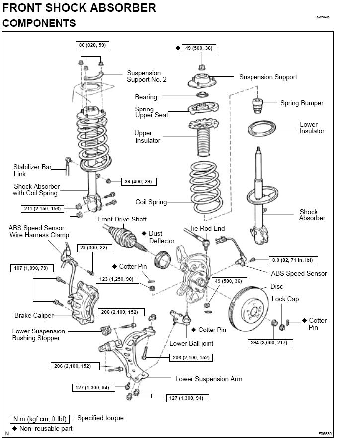 If either of these items are damaged, your strut may no longer be held properly by the strut mount. If this is the case, you will definitely want to replace these parts as one of the things that can happen is that the spring may slide off the strut when hitting a bump. This will cause some pretty severe problems. The strut mount is pretty expensive...but it is definetely not worth it to wait. Here are the TSBs for 1997 xle v6: TSB # PG027-02 for Steering/Suspension - Ball Joint Inspection TSB # ST008-01 for Front Suspension - Squeaking TSB # SU001-00 for Suspension - Front Support Change Reduces Noise (a redesigned suspension support at the top of the strut tower) TSB # SU003-98 for Suspension - Groans From Front Driving Over Bumps (involves replacing the "bump" rubber on the strut shaft with a new piece featuring six additional ribs) TSB #SU00796 for Suspension - Rattle/Popping Noise From Front Q: What years of Camrys are susceptable to getting this noise from the defective strut towers? A: All Camrys '97 - '00 Q: Are the strut mounts easy to replace? having no experience w/ macpherson struts, my worst fear is unbolting the top off the strut mount and my last sight is seeing a spring launching out like a minuteman missile  A: You have to remove the strut from the car as an assembly, then use a spring compressor. Q: Are the front spring bumpers easy to replace? actually, i have no idea what this is. i'm assuming its probably some type of polyurethane or rubber bumper/bushing between the strut tower and the strut mount. please correct me if i'm wrong here. A: Spring Bumper- you will see it under the Upper strut mount/Upper Spring seat at the top of the strut shaft. Yes, they are easy to replace if you have a spring compressor to disassemble the strut. Q: Do i need any special tools? SST from Toyota? A: No. Just a spring compressor if you replace the shock. After changing these parts out, do i need to do a 2 wheel or 4 wheel alignment? A: No. Replacing the strut mounts does not change the steering or suspension geometry. Cautions: 1) Do not remove the center nut (on the upper strut mount) while you have the strut assembly removed from the car without the spring compressor installed properly on the spring (tension off the center nut). 2) If the Car has ABS Brakes be very careful with the ABS Sensor/ Wire ($$Expensive). When the strut is removed don't let the lower control arm hang by the ABS wire! Struts still in good shape? Now would be the time to change them! HINTS FOR THE WISE OK, I had the famous '97-99 clonking problem. After changing the sway bar links and bushings it was still there and I opted to change the strut mount. This is actually not hard at all, a little sweat and time is all it takes if you are aware of the following, which I learned: First lesson: The strut to control arm bolts are 22mm. Of course I had 17,18,19,20,21,23,24,25 mm but no 22mm. Now I have. Set me back 1/2 hour. Second lesson: The left and right side are different. It dos not say on the strut mount box (from KYB) nor in the Haynes (I think). It is not stamped on the new mounts. BUT it is stamped on the old ones. This is done so that when you throw out the old ones you realized that there is a difference. And have to do it over again, due to Murphys law. (You had 50% chance of getting it right, but you will get it wrong). I had the left strut out while I had put the left mount in the right side! So I thought: "Just use the old left mount, but change the bearing as these are the ones always wearing out on other cars, then I can just change the right mount back mount". This brings me to lesson #3: Thrid Lesson: It is the strut mount that is worn, not the bearing. After finishing up, I drove to the Diner. And the left side with the old mount/new bearing was still making noise. !$#@. Back on the Jack Stand, changing the strut mount and putting it back together. But now everything is quiet. That is, now I can hear my rear mounts clonking.......... All in all, with some help from my father in law compressing the springs (this helps) it took me from 10:30AM to 5PM, including lunch and a trip for the right socket. Hope this will help someone not do the same mistakes I did and get the job done faster. ----------------------- PS Use a torque wrench 'cause it is surprising how tight some of the nuts have to be tightened and others not. PPS I got my strut mounts (KYB OEM) at autopartswarehouse.com. ~$65 each + two day shipping.. Much cheaper than local, non-oem. PPS My struts are original ('97) and in fine shape, rear ones just changed 'cause they were out. Thanks joopa
__________________
Forum Guidelines:http://www.automotiveforums.com/vbulletin/guidelines.html "What we've got here is a failure to communicate" Last edited by Brian R.; 01-18-2008 at 11:42 PM. |
|
|
|
|
06-30-2005, 01:34 AM
|
#20 | |
|
Resident Chemist
Join Date: Feb 2004
Location: Rockville, Maryland
Posts: 8,586
Thanks: 105
Thanked 157 Times in 157 Posts
|
Re: Camry FAQs and Information
CHECK ENGINE LIGHT IN '94 CAMRY
Q: My 94 Camry check engine light has just come on recently. I've never seen it on until now and I don't know why. The car has 148k miles on it, what could be the problem? I have tried checking the code myself using the paperclip method that I found on this site, but could not get anything out of it. The light just stays on and does not blink once. How can I check the code? Is there a reset button or anything I can do? Any help is appreciated. TIA. A: Your car maybe OBDII compliant which means you need a code reader. Check on the label attached to the underside of your hood. See if it says OBDII certified. http://www.iequus.com/assets/manuals/3100E.pdf OBD Codes: http://autorepair.about.com/od/obdco...gine_Codes.htm Q: Can I purchase a reader at any autoshop? How much are they? A: You need an adapter that is specific for Toyota. Most readers will work with the appropriate adapter. I have had trouble finding the right adapter at my local stores. I think online is the best place to buy one. I think prices are $100 on up. One that monitors engine functions is particularly useful - feeds data into computer like notebook or hand-held pc. If you live near an Autozone store, they will check it for free. Q: I went to a Autozone store and they said that they could only do 96 and up. Is that true? A: 1996 and later cars have to be OBDII compliant. Toyota made their 1994 and 1995 V6 Camrys OBDII compliant. If your car is, then point it out to him and they should check it. Check your emissions sticker under the hood. It will tell you if your car is OBDII compliant or not.
__________________
Forum Guidelines:http://www.automotiveforums.com/vbulletin/guidelines.html "What we've got here is a failure to communicate" Last edited by Brian R.; 05-24-2008 at 04:18 PM. |
|
|
|
|
06-30-2005, 01:44 AM
|
#21 | |
|
Resident Chemist
Join Date: Feb 2004
Location: Rockville, Maryland
Posts: 8,586
Thanks: 105
Thanked 157 Times in 157 Posts
|
Re: Camry FAQs and Information
OBDII DTC CODES
Get DENSO (OEM) part numbers here. A primer on OBDII DTC codes: http://www.overboost.com/story.asp?id=1286&r=1 See also: http://www.obd-codes.com/trouble_codes/index.php Here are a list of generic and Toyota-specific DTC codes from http://www.iequus.com/assets/manuals/3100E.pdf DTC Codes in BOLD have additional information or troubleshooting guide at the end of this post. The above document also provided Manufacturer-specific DTC codes for Honda, General Motors, Ford, and Chrysler. DIAGNOSTIC TROUBLE CODE DEFINITIONS The following Diagnostic Trouble Code Definitions lists represent the most complete information currently available. OBD II is an evolving system, and new codes and definitions will be added as the system matures. ALWAYS consult the vehicle’s service manual for code definitions not included in these lists. The following code definition lists provide both Generic Diagnostic Trouble Code Definitions and Manufacturer-Specific Diagnostic Trouble Code Definitions for the following vehicles: • OBD II Powertrain “GENERIC” (P0XXX) Diagnostic Trouble Codes. OBD II Generic Diagnostic Trouble Codes and their definitions apply to all makes and models of import and domestic vehicles that are “OBD II COMPLIANT”. • OBD II Powertrain “MANUFACTURER SPECIFIC” (P1XXX) Diagnostic Trouble Codes. OBD II Manufacturer-Specific Diagnostic Trouble Codes and their definitions apply only to vehicles produced by the specific manufacturer (Ford, GM, Toyota etc.). GENERIC OBD II CODE DEFINITIONS P0010 "A" Camshaft Position Actuator Circuit (Bank 1) P0011 "A" Camshaft Position - Timing Over-Advanced or System Performance (Bank 1) P0012 "A" Camshaft Position - Timing Over-Retarded (Bank 1) P0013 "B" Camshaft Position - Actuator Circuit (Bank 1) P0014 "B" Camshaft Position - Timing Over-Advanced or System Performance (Bank 1) P0015 "B" Camshaft Position - Timing Over-Retarded (Bank 1) P0016 Crankshaft Position - Camshaft Position Correlation - Bank 1 Sensor A P0020 "A" Camshaft Position Actuator Circuit (Bank 2) P0021 "A" Camshaft Position - Timing Over-Advanced or System Performance (Bank 2) P0022 "A" Camshaft Position - Timing Over-Retarded (Bank 2) P0023 "B" Camshaft Position - Actuator Circuit (Bank 2) P0024 "B" Camshaft Position - Timing Over-Advanced or System Performance (Bank 2) P0025 "B" Camshaft Position - Timing Over-Retarded (Bank 2) P0030 HO2S Heater Control Circuit (Bank 1 Sensor 1) P0031 HO2S Heater Control Circuit Low (Bank 1 Sensor 1) P0032 HO2S Heater Control Circuit High (Bank 1 Sensor 1) P0033 Turbo Charger Bypass Valve Control Circuit P0034 Turbo Charger Bypass Valve Control Circuit Low P0035 Turbo Charger Bypass Valve Control Circuit High P0036 HO2S Heater Control Circuit (Bank 1 Sensor 2) P0037 HO2S Heater Control Circuit Low (Bank 1 Sensor 2) P0038 HO2S Heater Control Circuit High (Bank 1 Sensor 2) P0042 HO2S Heater Control Circuit (Bank 1 Sensor 3) P0043 HO2S Heater Control Circuit Low (Bank 1 Sensor 3) P0044 HO2S Heater Control Circuit High (Bank 1 Sensor 3) P0050 HO2S Heater Control Circuit (Bank 2 Sensor 1) P0051 HO2S Heater Control Circuit Low (Bank 2 Sensor 1) P0052 HO2S Heater Control Circuit High (Bank 2 Sensor 1) P0056 HO2S Heater Control Circuit (Bank 2 Sensor 2) P0057 HO2S Heater Control Circuit Low (Bank 2 Sensor 2) P0058 HO2S Heater Control Circuit High (Bank 2 Sensor 2) P0062 HO2S Heater Control Circuit (Bank 2 Sensor 3) P0063 HO2S Heater Control Circuit Low (Bank 2 Sensor 3) P0064 HO2S Heater Control Circuit High (Bank 2 Sensor 3) P0065 Air Assisted Injector Control Range/Performance P0066 Air Assisted Injector Control Circuit or Circuit Low P0067 Air Assisted Injector Control Circuit High P0070 Ambient Air Temperature Sensor Circuit P0071 Ambient Air Temperature Sensor Range/Performance P0072 Ambient Air Temperature Sensor Circuit Low Input P0073 Ambient Air Temperature Sensor Circuit High Input P0074 Ambient Air Temperature Sensor Circuit Intermittent P0075 Intake Valve Control Solenoid Circuit (Bank 1) P0076 Intake Valve Control Solenoid Circuit Low (Bank 1) P0077 Intake Valve Control Solenoid Circuit High (Bank 1) P0078 Exhaust Valve Control Solenoid Circuit (Bank 1) P0079 Exhaust Valve Control Solenoid Circuit Low (Bank 1) P0080 Exhaust Valve Control Solenoid Circuit High (Bank 1) P0081 Intake Valve Control Solenoid Circuit (Bank 2) P0082 Intake Valve Control Solenoid Circuit Low (Bank 2) P0083 Intake Valve Control Solenoid Circuit High (Bank 2) P0084 Exhaust Valve Control Solenoid Circuit (Bank 2) P0085 Exhaust Valve Control Solenoid Circuit Low (Bank 2) P0086 Exhaust Valve Control Solenoid Circuit High (Bank 2) P0100 Mass or Volume Air Flow Circuit Malfunction P0101 Mass or Volume Circuit Range/Performance Problem P0102 Mass or Volume Circuit Low Input P0103 Mass or Volume Circuit High Input P0104 Mass or Volume Circuit Intermittent P0105 Manifold Absolute Pressure/Barometric Pressure Circuit Malfunction P0106 Manifold Absolute Pressure/Barometric Pressure Circuit Range/Performance Problem P0107 Manifold Absolute Pressure/Barometric Pressure Circuit Low Input P0108 Manifold Absolute Pressure/Barometric Pressure Circuit High Input P0109 Manifold Absolute Pressure/Barometric Pressure Circuit Intermittent P0110 Intake Air Temperature Circuit Malfunction P0111 Intake Air Temperature Circuit Range/Performance Problem P0112 Intake Air Temperature Circuit Low Input P0113 Intake Air Temperature Circuit High Input P0114 Intake Air Temperature Circuit Intermittent P0115 Engine Coolant Temperature Circuit Malfunction P0116 Engine Coolant Temperature Circuit Range/Performance Problem P0117 Engine Coolant Temperature Circuit Low Input P0118 Engine Coolant Temperature Circuit High Input P0119 Engine Coolant Temperature Circuit Intermittent P0120 Throttle/Pedal Position Sensor/Switch A Circuit Malfunction P0121 Throttle/Pedal Position Sensor/Switch A Circuit Range/Performance Problem P0122 Throttle/Pedal Position Sensor/Switch A Circuit Low Input P0123 Throttle/Pedal Position Sensor/Switch A Circuit High Input P0124 Throttle/Pedal Position Sensor/Switch A Circuit Intermittent P0125 Insufficient Coolant Temperature for Closed Loop Fuel Control P0126 Insufficient Coolant Temperature for Stable Operation P0127 Intake Air Temperature Too High P0128 Coolant Thermostat (Coolant Temperature Below Thermostat Regulating Temperature) P0130 O2 Sensor Circuit Malfunction (Bank 1 Sensor 1) P0131 O2 Sensor Circuit Low Voltage (Bank 1 Sensor 1) P0132 O2 Sensor Circuit High Voltage (Bank 1 Sensor 1) P0133 O2 Sensor Circuit Slow Response (Bank 1 Sensor 1) P0134 O2 Sensor Circuit No Activity Detected (Bank 1 Sensor 1) P0135 O2 Sensor Heater Circuit Malfunction (Bank 1 Sensor 1) P0136 O2 Sensor Circuit Malfunction (Bank 1 Sensor 2) P0137 O2 Sensor Circuit Low Voltage (Bank 1 Sensor 2) P0138 O2 Sensor Circuit High Voltage (Bank 1 Sensor 2) P0139 O2 Sensor Circuit Slow Response (Bank 1 Sensor 2) P0140 O2 Sensor Circuit No Activity Detected (Bank 1 Sensor 2) P0141 O2 Sensor Heater Circuit Malfunction (Bank 1 Sensor 2) P0142 O2 Sensor Circuit Malfunction (Bank 1 Sensor 3) P0143 O2 Sensor Circuit Low Voltage (Bank 1 Sensor 3) P0144 O2 Sensor Circuit High Voltage (Bank 1 Sensor 3) P0145 O2 Sensor Circuit Slow Response (Bank 1 Sensor 3) P0146 O2 Sensor Circuit No Activity Detected (Bank 1 Sensor 3) P0147 O2 Sensor Heater Circuit Malfunction (Bank 1 Sensor 3) P0148 Fuel Delivery Error P0149 Fuel Timing Error P0150 O2 Sensor Circuit Malfunction (Bank 2 Sensor 1) P0151 O2 Sensor Circuit Low Voltage (Bank 2 Sensor 1) P0152 O2 Sensor Circuit High Voltage (Bank 2 Sensor 1) P0153 O2 Sensor Circuit Slow Response (Bank 2 Sensor 1) P0154 O2 Sensor Circuit No Activity Detected (Bank 2 Sensor 1) P0155 O2 Sensor Heater Circuit Malfunction (Bank 2 Sensor 1) P0156 O2 Sensor Circuit Malfunction (Bank 2 Sensor 2) P0157 O2 Sensor Circuit Low Voltage (Bank 2 Sensor 2) P0158 O2 Sensor Circuit High Voltage (Bank 2 Sensor 2) P0159 O2 Sensor Circuit Slow Response (Bank 2 Sensor 2) P0160 O2 Sensor Circuit No Activity Detected (Bank 2 Sensor 2) P0161 O2 Sensor Heater Circuit Malfunction (Bank 2 Sensor 2) P0162 O2 Sensor Circuit Malfunction (Bank 2 Sensor 3) P0163 O2 Sensor Circuit Low Voltage (Bank 2 Sensor 3) P0164 O2 Sensor Circuit High Voltage (Bank 2 Sensor 3) P0165 O2 Sensor Circuit Slow Response (Bank 2 Sensor 3) P0166 O2 Sensor Circuit No Activity Detected (Bank 2 Sensor 3) P0167 O2 Sensor Heater Circuit Malfunction (Bank 2 Sensor 3) P0168 Fuel Temperature Too High P0169 Incorrect Fuel Composition P0170 Fuel Trim Malfunction (Bank 1) P0171 System too Lean (Bank 1) P0172 System too Rich (Bank 1) P0173 Fuel Trim Malfunction (Bank 2) P0174 System too Lean (Bank 2) P0175 System too Rich (Bank 2) P0176 Fuel Composition Sensor Circuit Malfunction P0177 Fuel Composition Sensor Circuit Range/Performance P0178 Fuel Composition Sensor Circuit Low Input P0179 Fuel Composition Sensor Circuit High Input P0180 Fuel Temperature Sensor A Circuit Malfunction P0181 Fuel Temperature Sensor A Circuit Range/Performance P0182 Fuel Temperature Sensor A Circuit Low Input P0183 Fuel Temperature Sensor A Circuit High Input P0184 Fuel Temperature Sensor A Circuit Intermittent P0185 Fuel Temperature Sensor B Circuit Malfunction P0186 Fuel Temperature Sensor B Circuit Range/Performance P0187 Fuel Temperature Sensor B Circuit Low Input P0188 Fuel Temperature Sensor B Circuit High Input P0189 Fuel Temperature Sensor B Circuit Intermittent P0190 Fuel Rail Pressure Sensor Circuit Malfunction P0191 Fuel Rail Pressure Sensor Circuit Range/Performance P0192 Fuel Rail Pressure Sensor Circuit Low Input P0193 Fuel Rail Pressure Sensor Circuit High Input P0194 Fuel Rail Pressure Sensor Circuit Intermittent P0195 Engine Oil Temperature Sensor Malfunction P0196 Engine Oil Temperature Sensor Range/Performance P0197 Engine Oil Temperature Sensor Low P0198 Engine Oil Temperature Sensor High P0199 Engine Oil Temperature Sensor Intermittent P0200 Injector Circuit Malfunction P0201 Injector Circuit Malfunction - Cylinder 1 P0202 Injector Circuit Malfunction - Cylinder 2 P0203 Injector Circuit Malfunction - Cylinder 3 P0204 Injector Circuit Malfunction - Cylinder 4 P0205 Injector Circuit Malfunction - Cylinder 5 P0206 Injector Circuit Malfunction - Cylinder 6 P0207 Injector Circuit Malfunction - Cylinder 7 P0208 Injector Circuit Malfunction - Cylinder 8 P0209 Injector Circuit Malfunction - Cylinder 9 P0210 Injector Circuit Malfunction - Cylinder 10 P0211 Injector Circuit Malfunction - Cylinder 11 P0212 Injector Circuit Malfunction - Cylinder 12 P0213 Cold Start Injector 1 Malfunction P0214 Cold Start Injector 2 Malfunction P0215 Engine Shutoff Solenoid Malfunction P0216 Injection Timing Control Circuit Malfunction P0217 Engine Overtemp Condition P0218 Transmission Over Temperature Condition P0219 Engine Overspeed Condition P0220 Throttle/Pedal Position Sensor/Switch B Circuit Malfunction P0221 Throttle/Pedal Position Sensor/Switch B Circuit Range/Performance Problem P0222 Throttle/Pedal Position Sensor/Switch B Circuit Low Input P0223 Throttle/Pedal Position Sensor/Switch B Circuit High Input P0224 Throttle/Pedal Position Sensor/Switch B Circuit Intermittent P0225 Throttle/Pedal Position Sensor/Switch C Circuit Malfunction P0226 Throttle/Pedal Position Sensor/Switch C Circuit Range/Performance Problem P0227 Throttle/Pedal Position Sensor/Switch C Circuit Low Input P0228 Throttle/Pedal Position Sensor/Switch C Circuit High Input P0229 Throttle/Pedal Position Sensor/Switch C Circuit Intermittent P0230 Fuel Pump Primary Circuit Malfunction P0231 Fuel Pump Secondary Circuit Low P0232 Fuel Pump Secondary Circuit High P0233 Fuel Pump Secondary Circuit Intermittent P0234 Engine Overboost Condition P0235 Turbocharger Boost Sensor A Circuit Malfunction P0236 Turbocharger Boost Sensor A Circuit Range/Performance P0237 Turbocharger Boost Sensor A Circuit Low P0238 Turbocharger Boost Sensor A Circuit High P0239 Turbocharger Boost Sensor B Circuit Malfunction P0240 Turbocharger Boost Sensor B Circuit Range/Performance P0241 Turbocharger Boost Sensor B Circuit Low P0242 Turbocharger Boost Sensor B Circuit High P0243 Turbocharger Wastegate Solenoid A Malfunction P0244 Turbocharger Wastegate Solenoid A Range/Performance P0245 Turbocharger Wastegate Solenoid A Low P0246 Turbocharger Wastegate Solenoid A High P0247 Turbocharger Wastegate Solenoid B Malfunction P0248 Turbocharger Wastegate Solenoid B Range/Performance P0249 Turbocharger Wastegate Solenoid B Low P0250 Turbocharger Wastegate Solenoid B High P0251 Injection Pump A Rotor/Cam Malfunction P0252 Injection Pump A Rotor/Cam Range/Performance P0253 Injection Pump A Rotor/Cam Low P0254 Injection Pump A Rotor/Cam High P0255 Injection Pump A Rotor/Cam Intermitted P0256 Injection Pump B Rotor/Cam Malfunction P0257 Injection Pump B Rotor/Cam Range/Performance P0258 Injection Pump B Rotor/Cam Low P0259 Injection Pump B Rotor/Cam High P0260 Injection Pump B Rotor/Cam Intermitted P0261 Cylinder 1 Injector Circuit Low P0262 Cylinder 1 Injector Circuit High P0263 Cylinder 1 Contribution/Balance Fault P0264 Cylinder 2 Injector Circuit Low P0265 Cylinder 2 Injector Circuit High P0266 Cylinder 2 Contribution/Balance Fault P0267 Cylinder 3 Injector Circuit Low P0268 Cylinder 3 Injector Circuit High P0269 Cylinder 3 Contribution/Balance Fault P0270 Cylinder 4 Injector Circuit Low P0271 Cylinder 4 Injector Circuit High P0272 Cylinder 4 Contribution/Balance Fault P0273 Cylinder 5 Injector Circuit Low P0274 Cylinder 5 Injector Circuit High P0275 Cylinder 5 Contribution/Balance Fault P0276 Cylinder 6 Injector Circuit Low P0277 Cylinder 6 Injector Circuit High P0278 Cylinder 6 Contribution/Balance Fault P0279 Cylinder 7 Injector Circuit Low P0280 Cylinder 7 Injector Circuit High P0281 Cylinder 7 Contribution/Balance Fault P0282 Cylinder 8 Injector Circuit Low P0283 Cylinder 8 Injector Circuit High P0284 Cylinder 8 Contribution/Balance Fault P0285 Cylinder 9 Injector Circuit Low P0286 Cylinder 9 Injector Circuit High P0287 Cylinder 9 Contribution/Balance Fault P0288 Cylinder 10 Injector Circuit Low P0289 Cylinder 10 Injector Circuit High P0290 Cylinder 10 Contribution/Balance Fault P0291 Cylinder 11 Injector Circuit Low P0292 Cylinder 11 Injector Circuit High P0293 Cylinder 11 Contribution/Balance Fault P0294 Cylinder 12 Injector Circuit Low P0295 Cylinder 12 Injector Circuit High P0296 Cylinder 12 Contribution/Balance Fault P0298 Engine Oil Over Temperature P0300 Random/Multiple Cylinder Misfire Detected P0301 Cylinder 1 Misfire Detected P0302 Cylinder 2 Misfire Detected P0303 Cylinder 3 Misfire Detected P0304 Cylinder 4 Misfire Detected P0305 Cylinder 5 Misfire Detected P0306 Cylinder 6 Misfire Detected P0307 Cylinder 7 Misfire Detected P0308 Cylinder 8 Misfire Detected P0309 Cylinder 9 Misfire Detected P0310 Cylinder 10 Misfire Detected P0311 Cylinder 11 Misfire Detected P0312 Cylinder 12 Misfire Detected P0313 Misfire Detected with Low Fuel P0314 Single Cylinder Misfire (Cylinder not specified) P0320 Ignition/Distributor Engine Speed Input Circuit Malfunction P0321 Ignition/Distributor Engine Speed Input Circuit Range/Performance P0322 Ignition/Distributor Engine Speed Input Circuit No Signal P0323 Ignition/Distributor Engine Speed Input Circuit Intermittent P0324 Knock Control System Error P0325 Knock Sensor 1 Circuit Malfunction (Bank 1 or Single Sensor) P0326 Knock Sensor 1 Circuit Range/Performance (Bank 1 or Single Sensor) P0327 Knock Sensor 1 Circuit Low Input (Bank 1 or Single Sensor) P0328 Knock Sensor 1 Circuit High Input (Bank 1 or Single Sensor) P0329 Knock Sensor 1 Circuit Intermittent (Bank 1 or Single Sensor) P0330 Knock Sensor 2 Circuit Malfunction (Bank 2) P0331 Knock Sensor 2 Circuit Range/Performance (Bank 2) P0332 Knock Sensor 2 Circuit Low Input (Bank 2) P0333 Knock Sensor 2 Circuit High Input (Bank 2) P0334 Knock Sensor 2 Circuit Intermittent (Bank 2) P0335 Crankshaft Position Sensor A Circuit Malfunction P0336 Crankshaft Position Sensor A Circuit Range/Performance P0337 Crankshaft Position Sensor A Circuit Low Input P0338 Crankshaft Position Sensor A Circuit High Input P0339 Crankshaft Position Sensor A Circuit Intermittent P0340 Camshaft Position Sensor Circuit Malfunction P0341 Camshaft Position Sensor Circuit Range/Performance P0342 Camshaft Position Sensor Circuit Low Input P0343 Camshaft Position Sensor Circuit High Input P0344 Camshaft Position Sensor Circuit Intermittent P0345 Camshaft Position Sensor "A" Circuit (Bank 2) P0346 Camshaft Position Sensor "A" Circuit Range/Performance (Bank 2) P0347 Camshaft Position Sensor "A" Circuit Low Input (Bank 2) P0348 Camshaft Position Sensor "A" Circuit High Input (Bank 2) P0349 Camshaft Position Sensor "A" Circuit Intermittent (Bank 2) P0350 Ignition Coil Primary/Secondary Circuit Malfunction P0351 Ignition Coil A Primary/Secondary Circuit Malfunction P0352 Ignition Coil B Primary/Secondary Circuit Malfunction P0353 Ignition Coil C Primary/Secondary Circuit Malfunction P0354 Ignition Coil D Primary/Secondary Circuit Malfunction P0355 Ignition Coil E Primary/Secondary Circuit Malfunction P0356 Ignition Coil F Primary/Secondary Circuit Malfunction P0357 Ignition Coil G Primary/Secondary Circuit Malfunction P0358 Ignition Coil H Primary/Secondary Circuit Malfunction P0359 Ignition Coil I Primary/Secondary Circuit Malfunction P0360 Ignition Coil J Primary/Secondary Circuit Malfunction P0361 Ignition Coil K Primary/Secondary Circuit Malfunction P0362 Ignition Coil L Primary/Secondary Circuit Malfunction P0365 Camshaft Position Sensor "B" Circuit (Bank 1) P0366 Camshaft Position Sensor "B" Circuit Range/Performance (Bank 1) P0367 Camshaft Position Sensor "B" Circuit Low Input (Bank 1) P0368 Camshaft Position Sensor "B" Circuit High Input (Bank 1) P0369 Camshaft Position Sensor "B" Circuit Intermittent (Bank 1) P0370 Timing Reference High Resolution Signal A Malfunction P0371 Timing Reference High Resolution Signal A Too Many Pulses P0372 Timing Reference High Resolution Signal A Too Few Pulses P0373 Timing Reference High Resolution Signal A Intermittent/ Erratic Pulses P0374 Timing Reference High Resolution Signal A No Pulses P0375 Timing Reference High Resolution Signal B Malfunction P0376 Timing Reference High Resolution Signal B Too Many Pulses P0377 Timing Reference High Resolution Signal B Too Few Pulses P0378 Timing Reference High Resolution Signal B Intermittent/ Erratic Pulses P0379 Timing Reference High Resolution Signal B No Pulses P0380 Glow Plug/Heater Circuit Malfunction P0381 Glow Plug/Heater Indicator Circuit Malfunction P0382 Glow Plug/Heater Circuit "B" Malfunction P0385 Crankshaft Position Sensor B Circuit Malfunction P0386 Crankshaft Position Sensor B Circuit Range/Performance P0387 Crankshaft Position Sensor B Circuit Low Input P0388 Crankshaft Position Sensor B Circuit High Input P0389 Crankshaft Position Sensor B Circuit Intermittent P0390 Camshaft Position Sensor "B" Circuit (Bank 2) P0391 Camshaft Position Sensor "B" Circuit Range/Performance (Bank 2) P0392 Camshaft Position Sensor "B" Circuit Low Input (Bank 2) P0393 Camshaft Position Sensor "B" Circuit High Input (Bank 2) P0394 Camshaft Position Sensor "B" Circuit Intermittent (Bank 2) P0400 Exhaust Gas Recirculation Flow Malfunction P0401 Exhaust Gas Recirculation Flow Insufficient Detected P0402 Exhaust Gas Recirculation Flow Excessive Detected P0403 Exhaust Gas Recirculation Circuit Malfunction P0404 Exhaust Gas Recirculation Circuit Range/Performance P0405 Exhaust Gas Recirculation Sensor A Circuit Low P0406 Exhaust Gas Recirculation Sensor A Circuit High P0407 Exhaust Gas Recirculation Sensor B Circuit Low P0408 Exhaust Gas Recirculation Sensor B Circuit High P0409 Exhaust Gas Recirculation Sensor "A" Circuit P0410 Secondary Air Injection System Malfunction P0411 Secondary Air Injection System Incorrect Flow Detected P0412 Secondary Air Injection System Switching Valve A Circuit Malfunction P0413 Secondary Air Injection System Switching Valve A Circuit Open P0414 Secondary Air Injection System Switching Valve A Circuit Shorted P0415 Secondary Air Injection System Switching Valve B Circuit Malfunction P0416 Secondary Air Injection System Switching Valve B Circuit Open P0417 Secondary Air Injection System Switching Valve B Circuit Shorted P0418 Secondary Air Injection System Relay "A" Circuit Malfunction P0419 Secondary Air Injection System Relay "B" Circuit Malfunction P0420 Catalyst System Efficiency Below Threshold (Bank 1) P0421 Warm Up Catalyst Efficiency Below Threshold (Bank 1) P0422 Main Catalyst Efficiency Below Threshold (Bank 1) P0423 Heated Catalyst Efficiency Below Threshold (Bank 1) P0424 Heated Catalyst Temperature Below Threshold (Bank 1) P0425 Catalyst Temperature Sensor (Bank 1) P0426 Catalyst Temperature Sensor Range/Performance (Bank 1) P0427 Catalyst Temperature Sensor Low Input (Bank 1) P0428 Catalyst Temperature Sensor High Input (Bank 1) P0429 Catalyst Heater Control Circuit (Bank 1) P0430 Catalyst System Efficiency Below Threshold (Bank 2) P0431 Warm Up Catalyst Efficiency Below Threshold (Bank 2) P0432 Main Catalyst Efficiency Below Threshold (Bank 2) P0433 Heated Catalyst Efficiency Below Threshold (Bank 2) P0434 Heated Catalyst Temperature Below Threshold (Bank 2) P0435 Catalyst Temperature Sensor (Bank 2) P0436 Catalyst Temperature Sensor Range/Performance (Bank 2) P0437 Catalyst Temperature Sensor Low Input (Bank 2) P0438 Catalyst Temperature Sensor High Input (Bank 2) P0439 Catalyst Heater Control Circuit (Bank 2) P0440 Evaporative Emission Control System Malfunction P0441 Evaporative Emission Control System Incorrect Purge Flow P0442 Evaporative Emission Control System Leak Detected (small leak) P0443 Evaporative Emission Control System Purge Control Valve Circuit Malfunction P0444 Evaporative Emission Control System Purge Control Valve Circuit Open P0445 Evaporative Emission Control System Purge Control Valve Circuit Shorted P0446 Evaporative Emission Control System Vent Control Circuit Malfunction P0447 Evaporative Emission Control System Vent Control Circuit Open P0448 Evaporative Emission Control System Vent Control Circuit Shorted P0449 Evaporative Emission Control System Vent Valve/Solenoid Circuit Malfunction P0450 Evaporative Emission Control System Pressure Sensor Malfunction P0451 Evaporative Emission Control System Pressure Sensor Range/Performance P0452 Evaporative Emission Control System Pressure Sensor Low Input P0453 Evaporative Emission Control System Pressure Sensor High Input P0454 Evaporative Emission Control System Pressure Sensor Intermittent P0455 Evaporative Emission Control System Leak Detected (gross leak) P0456 Evaporative Emission Control System Leak Detected (very small leak) P0457 Evaporative Emission Control System Leak Detected (fuel cap loose/off) P0460 Fuel Level Sensor Circuit Malfunction P0461 Fuel Level Sensor Circuit Range/Performance P0462 Fuel Level Sensor Circuit Low Input P0463 Fuel Level Sensor Circuit High Input P0464 Fuel Level Sensor Circuit Intermittent P0465 Purge Flow Sensor Circuit Malfunction P0466 Purge Flow Sensor Circuit Range/Performance P0467 Purge Flow Sensor Circuit Low Input P0468 Purge Flow Sensor Circuit High Input P0469 Purge Flow Sensor Circuit Intermittent P0470 Exhaust Pressure Sensor Malfunction P0471 Exhaust Pressure Sensor Range/Performance P0472 Exhaust Pressure Sensor Low P0473 Exhaust Pressure Sensor High P0474 Exhaust Pressure Sensor Intermittent P0475 Exhaust Pressure Control Valve Malfunction P0476 Exhaust Pressure Control Valve Range/Performance P0477 Exhaust Pressure Control Valve Low P0478 Exhaust Pressure Control Valve High P0479 Exhaust Pressure Control Valve Intermittent P0480 Cooling Fan 1 Control Circuit Malfunction P0481 Cooling Fan 2 Control Circuit Malfunction P0482 Cooling Fan 3 Control Circuit Malfunction P0483 Cooling Fan Rationality Check Malfunction P0484 Cooling Fan Circuit Over Current P0485 Cooling Fan Power/Ground Circuit Malfunction P0486 Exhaust Gas Recirculation Sensor "B" Circuit P0487 Exhaust Gas Recirculation Throttle Position Control Circuit P0488 Exhaust Gas Recirculation Throttle Position Control Range/Performance P0491 Secondary Air Injection System (Bank 1) P0492 Secondary Air Injection System (Bank 2) P0500 Vehicle Speed Sensor Malfunction P0501 Vehicle Speed Sensor Range/Performance P0502 Vehicle Speed Sensor Circuit Low Input P0503 Vehicle Speed Sensor Intermittent/Erratic/High P0505 Idle Control System Malfunction P0506 Idle Control System RPM Lower Than Expected P0507 Idle Control System RPM Higher Than Expected P0508 Idle Control System Circuit Low P0509 Idle Control System Circuit High P0510 Closed Throttle Position Switch Malfunction P0512 Starter Request Circuit P0513 Incorrect Immobilizer Key ("Immobilizer" pending SAE J1930 approval) P0515 Battery Temperature Sensor Circuit P0516 Battery Temperature Sensor Circuit Low P0517 Battery Temperature Sensor Circuit High P0520 Engine Oil Pressure/Switch Circuit Malfunction P0521 Engine Oil Pressure/Switch Range/Performance P0522 Engine Oil Pressure/Switch Low Voltage P0523 Engine Oil Pressure/Switch High Voltage P0524 Engine Oil Pressure Too Low P0530 A/C Refrigerant Pressure Sensor Circuit Malfunction P0531 A/C Refrigerant Pressure Sensor Circuit Range/Performance P0532 A/C Refrigerant Pressure Sensor Circuit Low Input P0533 A/C Refrigerant Pressure Sensor Circuit High Input P0534 Air Conditioner Refrigerant Charge Loss P0540 Intake Air Heater Circuit P0541 Intake Air Heater Circuit Low P0542 Intake Air Heater Circuit High P0544 Exhaust Gas Temperature Sensor Circuit (Bank 1) P0545 Exhaust Gas Temperature Sensor Circuit Low (Bank 1) P0546 Exhaust Gas Temperature Sensor Circuit High (Bank 1) P0547 Exhaust Gas Temperature Sensor Circuit (Bank 2) P0548 Exhaust Gas Temperature Sensor Circuit Low (Bank 2) P0549 Exhaust Gas Temperature Sensor Circuit High (Bank 2) P0550 Power Steering Pressure Sensor Circuit Malfunction P0551 Power Steering Pressure Sensor Circuit Range/Performance P0552 Power Steering Pressure Sensor Circuit Low Input P0553 Power Steering Pressure Sensor Circuit High Input P0554 Power Steering Pressure Sensor Circuit Intermittent P0560 System Voltage Malfunction P0561 System Voltage Unstable P0562 System Voltage Low P0563 System Voltage High P0564 Cruise Control Multi-Function Input Signal P0565 Cruise Control On Signal Malfunction P0566 Cruise Control Off Signal Malfunction P0567 Cruise Control Resume Signal Malfunction P0568 Cruise Control Set Signal Malfunction P0569 Cruise Control Coast Signal Malfunction P0570 Cruise Control Accel Signal Malfunction P0571 Cruise Control/Brake Switch A Circuit Malfunction P0572 Cruise Control/Brake Switch A Circuit Low P0573 Cruise Control/Brake Switch A Circuit High P0574 Cruise Control System - Vehicle Speed Too High P0575 Cruise Control Input Circuit P0576 Cruise Control Input Circuit Low P0577 Cruise Control Input Circuit High P0578-P0580 Reserved for Cruise Control Codes P0600 Serial Communication Link Malfunction P0601 Internal Control Module Memory Check Sum Error P0602 Control Module Programming Error P0603 Internal Control Module Keep Alive Memory (KAM) Error P0604 Internal Control Module Random Access Memory (RAM) Error P0605 Internal Control Module Read Only Memory (ROM) Error P0606 PCM Processor Fault P0607 Control Module Performance P0608 Control Module VSS Output "A" Malfunction P0609 Control Module VSS Output "B" Malfunction P0610 Control Module Vehicle Options Error P0615 Starter Relay Circuit P0616 Starter Relay Circuit Low P0617 Starter Relay Circuit High P0618 Alternative Fuel Control Module KAM Error P0619 Alternative Fuel Control Module RAM/ROM Error P0620 Generator Control Circuit Malfunction P0621 Generator Lamp "L" Control Circuit Malfunction P0622 Generator Field "F" Control Circuit Malfunction P0623 Generator Lamp Control Circuit P0624 Fuel Cap Lamp Control Circuit P0630 VIN Not Programmed or Mismatch - ECM/PCM P0631 VIN Not Programmed or Mismatch - TCM P0635 Power Steering Control Circuit P0636 Power Steering Control Circuit Low P0637 Power Steering Control Circuit High P0638 Throttle Actuator Control Range/Performance (Bank 1) P0639 Throttle Actuator Control Range/Performance (Bank 2) P0640 Intake Air Heater Control Circuit P0645 A/C Clutch Relay Control Circuit P0646 A/C Clutch Relay Control Circuit Low P0647 A/C Clutch Relay Control Circuit High P0648 Immobilizer Lamp Control Circuit ("Immobilizer" pending SAE J1930 approval) P0649 Speed Control Lamp Control Circuit P0650 Malfunction Indicator Lamp (MIL) Control Circuit Malfunction P0654 Engine RPM Output Circuit Malfunction P0655 Engine Hot Lamp Output Control Circuit Malfunction P0656 Fuel Level Output Circuit Malfunction P0660 Intake Manifold Tuning Valve Control Circuit (Bank 1) P0661 Intake Manifold Tuning Valve Control Circuit Low (Bank 1) P0662 Intake Manifold Tuning Valve Control Circuit High (Bank 1) P0663 Intake Manifold Tuning Valve Control Circuit (Bank 2) P0664 Intake Manifold Tuning Valve Control Circuit Low (Bank 2) P0665 Intake Manifold Tuning Valve Control Circuit High (Bank 2) P0700 Transmission Control System Malfunction P0701 Transmission Control System Range/Performance P0702 Transmission Control System Electrical P0703 Torque Converter/Brake Switch B Circuit Malfunction P0704 Clutch Switch Input Circuit Malfunction P0705 Transmission Range Sensor Circuit Malfunction (PRNDL Input) P0706 Transmission Range Sensor Circuit Range/Performance P0707 Transmission Range Sensor Circuit Low Input P0708 Transmission Range Sensor Circuit High Input P0709 Transmission Range Sensor Circuit Intermittent P0710 Transmission Fluid Temperature Sensor Circuit Malfunction P0711 Transmission Fluid Temperature Sensor Circuit Range/Performance P0712 Transmission Fluid Temperature Sensor Circuit Low Input P0713 Transmission Fluid Temperature Sensor Circuit High Input P0714 Transmission Fluid Temperature Sensor Circuit Intermittent P0715 Input/Turbine Speed Sensor Circuit Malfunction P0716 Input/Turbine Speed Sensor Circuit Range/Performance P0717 Input/Turbine Speed Sensor Circuit No Signal P0718 Input/Turbine Speed Sensor Circuit Intermittent P0719 Torque Converter/Brake Switch B Circuit Low P0720 Output Speed Sensor Circuit Malfunction P0721 Output Speed Sensor Circuit Range/Performance P0722 Output Speed Sensor Circuit No Signal P0723 Output Speed Sensor Circuit Intermittent P0724 Torque Converter/Brake Switch B Circuit High P0725 Engine Speed Input Circuit Malfunction P0726 Engine Speed Input Circuit Range/Performance P0727 Engine Speed Input Circuit No Signal P0728 Engine Speed Input Circuit Intermittent P0730 Incorrect Gear Ratio P0731 Gear 1 Incorrect Ratio P0732 Gear 2 Incorrect Ratio P0733 Gear 3 Incorrect Ratio P0734 Gear 4 Incorrect Ratio P0735 Gear 5 Incorrect Ratio P0736 Reverse Incorrect Ratio P0737 TCM Engine Speed Output Circuit P0738 TCM Engine Speed Output Circuit Low P0739 TCM Engine Speed Output Circuit High P0740 Torque Converter Clutch Circuit Malfunction P0741 Torque Converter Clutch Circuit Performance or Stuck Off P0742 Torque Converter Clutch Circuit Stuck On P0743 Torque Converter Clutch Circuit Electrical P0744 Torque Converter Clutch Circuit Intermittent P0745 Pressure Control Solenoid Malfunction P0746 Pressure Control Solenoid Performance or Stuck Off P0747 Pressure Control Solenoid Stuck On P0748 Pressure Control Solenoid Electrical P0749 Pressure Control Solenoid Intermittent P0750 Shift Solenoid A Malfunction P0751 Shift Solenoid A Performance or Stuck Off P0752 Shift Solenoid A Stuck On P0753 Shift Solenoid A Electrical P0754 Shift Solenoid A Intermittent P0755 Shift Solenoid B Malfunction P0756 Shift Solenoid B Performance or Stuck Off P0757 Shift Solenoid B Stuck On P0758 Shift Solenoid B Electrical P0759 Shift Solenoid B Intermittent P0760 Shift Solenoid C Malfunction P0761 Shift Solenoid C Performance or Stuck Off P0762 Shift Solenoid C Stuck On P0763 Shift Solenoid C Electrical P0764 Shift Solenoid C Intermittent P0765 Shift Solenoid D Malfunction P0766 Shift Solenoid D Performance or Stuck Off P0767 Shift Solenoid D Stuck On P0768 Shift Solenoid D Electrical P0769 Shift Solenoid D Intermittent P0770 Shift Solenoid E Malfunction P0771 Shift Solenoid E Performance or Stuck Off P0772 Shift Solenoid E Stuck On P0773 Shift Solenoid E Electrical P0774 Shift Solenoid E Intermittent P0775 Pressure Control Solenoid "B" P0776 Pressure Control Solenoid "B" Performance or Stuck Off P0777 Pressure Control Solenoid "B" Stuck On P0778 Pressure Control Solenoid "B" Electrical P0779 Pressure Control Solenoid "B" Intermittent P0780 Shift Malfunction P0781 1-2 Shift Malfunction P0782 2-3 Shift Malfunction P0783 3-4 Shift Malfunction P0784 4-5 Shift Malfunction P0785 Shift/Timing Solenoid Malfunction P0786 Shift/Timing Solenoid Range/Performance P0787 Shift/Timing Solenoid Low P0788 Shift/Timing Solenoid High P0789 Shift/Timing Solenoid Intermittent P0790 Normal/Performance Switch Circuit Malfunction P0791 Intermediate Shaft Speed Sensor Circuit P0792 Intermediate Shaft Speed Sensor Circuit Range/Performance P0793 Intermediate Shaft Speed Sensor Circuit No Signal P0794 Intermediate Shaft Speed Sensor Circuit Intermittent P0795 Pressure Control Solenoid "C" P0796 Pressure Control Solenoid "C" Performance or Stuck Off P0797 Pressure Control Solenoid "C" Stuck On P0798 Pressure Control Solenoid "C" Electrical P0799 Pressure Control Solenoid "C" Intermittent P0801 Reverse Inhibit Control Circuit Malfunction P0803 1-4 Upshift (Skip Shift) Solenoid Control Circuit Malfunction P0804 1-4 Upshift (Skip Shift) Lamp Control Circuit Malfunction P0805 Clutch Position Sensor Circuit P0806 Clutch Position Sensor Circuit Range/Performance P0807 Clutch Position Sensor Circuit Low P0808 Clutch Position Sensor Circuit High P0809 Clutch Position Sensor Circuit Intermittent P0810 Clutch Position Control Error P0811 Excessive Clutch Slippage P0812 Reverse Input Circuit P0813 Reverse Output Circuit P0814 Transmission Range Display Circuit P0815 Upshift Switch Circuit P0816 Downshift Switch Circuit P0817 Starter Disable Circuit P0818 Driveline Disconnect Switch Input Circuit P0820 Gear Lever X-Y Position Sensor Circuit P0821 Gear Lever X Position Circuit P0822 Gear Lever Y Position Circuit P0823 Gear Lever X Position Circuit Intermittent P0824 Gear Lever Y Position Circuit Intermittent P0825 Gear Lever Push-Pull Switch (Shift Anticipate) P0830 Clutch Pedal Switch "A" Circuit P0831 Clutch Pedal Switch "A" Circuit Low P0832 Clutch Pedal Switch "A" Circuit High P0833 Clutch Pedal Switch "B" Circuit P0834 Clutch Pedal Switch "B" Circuit Low P0835 Clutch Pedal Switch "B" Circuit High P0836 Four Wheel Drive (4WD) Switch Circuit P0837 Four Wheel Drive (4WD) Switch Circuit Range/Performance P0838 Four Wheel Drive (4WD) Switch Circuit Low P0839 Four Wheel Drive (4WD) Switch Circuit High P0840 Transmission Fluid Pressure Sensor/Switch "A" Circuit P0841 Transmission Fluid Pressure Sensor/Switch "A" Circuit Range/Performance P0842 Transmission Fluid Pressure Sensor/Switch "A" Circuit Low P0843 Transmission Fluid Pressure Sensor/Switch "A" Circuit High P0844 Transmission Fluid Pressure Sensor/Switch "A" Circuit Intermittent P0845 Transmission Fluid Pressure Sensor/Switch "B" Circuit P0846 Transmission Fluid Pressure Sensor/Switch "B" Circuit Range/Performance P0847 Transmission Fluid Pressure Sensor/Switch "B" Circuit Low P0848 Transmission Fluid Pressure Sensor/Switch "B" Circuit High P0849 Transmission Fluid Pressure Sensor/Switch "B" Circuit Intermittent TOYOTA-SPECIFIC OBD II CODE DEFINITIONS P1100 BARO Sensor Circuit malfunction P1120 Accelerator Pedal Position Sensor Circuit Malfunction P1121 Accelerator Pedal Position Sensor Range/Performance Problem P1125 Throttle Control Motor Circuit Malfunction P1126 Magnetic Clutch Circuit Malfunction P1127 ETCS Actuator Power Source Circuit Malfunction P1128 Throttle Control Motor Lock Malfunction P1129 Electric Throttle Control System Malfunction P1130 Air-Fuel Sensor Circuit Range/Performance P1133 Air-Fuel Sensor Circuit Response Malfunction P1135 Air-Fuel Sensor Heater Circuit Response Malfunction P1150 A/F Sensor Circuit Range/Performance Malfunction P1153 A./F Sensor Circuit Response Malfunction P1155 A/F Sensor Heater Circuit Malfunction P1200 Fuel Pump Relay Circuit Malfunction P1300 Igniter Circuit Malfunction No. 1 P1305 Igniter Circuit Malfunction No. 2 (1998-2000 Land Cruiser, 2000 Celica & Tundra) P1310 Igniter Circuit Malfunction No. 2 (Except 1998-2000 Land Cruiser, 2000 Celica & Tundra) P1310 Igniter Circuit Malfunction No. 3 (1998-2000 Land Cruiser, 2000 Celica & Tundra) P1315 Igniter Circuit Malfunction No. 4 (1998-2000 Land Cruiser, 2000 Celica & Tundra) P1320 Igniter Circuit Malfunction No. 5 (1998-2000 Land Cruiser & 2000 Tundra) P1325 Igniter Circuit Malfunction No. 6 (1998-2000 Land Cruiser & 2000 Tundra) P1330 Igniter Circuit Malfunction No. 7 (1998-2000 Land Cruiser & 2000 Tundra) P1335 No CKP Sensor Signal Engine Running P1340 Igniter Circuit Malfunction No. 8 (1998-2000 Land Cruiser & 2000 Tundra) P1346 VVT Sensor /Camshaft Position Sensor Circuit Range/Performance Problem (Bank 1) P1349 VVT System Malfunction P1351 VVT Sensor /Camshaft Position Sensor Circuit Range/Performance Problem (Bank 2) P1400 Sub-Throttle Position Sensor Malfunction P1401 Sub-Throttle Position Sensor Range/Performance Problem P1405 Turbo Pressure Sensor Circuit Malfunction P1406 Turbo Pressure Sensor Range/Performance Problem P1410 EGR Valve Position Sensor Circuit Malfunction P1411 EGR Valve Position Sensor Circuit Ranger/Performance P1500 Starter Signal Circuit Malfunction P1510 Boost Pressure Control Circuit Malfunction P1511 Boost Pressure Low Malfunction P1512 Boost Pressure High Malfunction P1520 Stop Lamp Switch Signal Malfunction P1565 Cruise Control Main Switch Circuit Malfunction P1600 ECM BATT Malfunction P1605 Knock Control CPU Malfunction P1630 Traction Control System Malfunction P1633 ECM Malfunction ECTS Circuit P1645 Body ECU Malfunction P1652 IACV Control Circuit Malfunction P1656 OCV Circuit Malfunction P1658 Waste Gate Valve Control Circuit Malfunction P1661 EGR Circuit Malfunction P1662 EGR By-Pass Valve Control Circuit Malfunction P1690 OCV Circuit Malfunction P1692 OCV Open Malfunction P1693 OCV Closed Malfunction P1780 PNP Switch Malfunction **************************** TROUBLESHOOTING SOME COMMON CODES P0011 "A" Camshaft Position - Timing Over-Advanced or System Performance (Bank 1) P0012 "A" Camshaft Position - Timing Over-Retarded (Bank 1) P0016 Crankshaft Position - Camshaft Position Correlation - Bank 1 Sensor A See: http://www.automotiveforums.com/vbul...d.php?t=692332 P0100 Mass or volume sensor or circuit Possible Problems MAF may be disconnected, or a wiring connection may be bad. MAF sensor may be faulty. Reset the code and see if it comes back. Verify that the Mass Air Flow Sensor wiring is connected properly and that there are no broken /frayed wires. Unplug and reconnect the MAF wiring harness Check the voltage of the MAF sensor (refer to a repair manual for vehicle specific information) Replace the MAF sensor P0101 Mass or volume Circuit Range/Performance Problem Possible Problems Mass Air Flow (MAF) sensor or circuit. The PCM detects that the actual MAF sensor frequency signal is not within a predetermined range of the calculated MAF value for more than 4.0 seconds. Reset the code and see if it comes back Inspect for the following conditions: An incorrectly routed harness--Inspect the harness of the MAF sensor in order to verify that it is not routed too close to the following components: - The secondary ignition wires or coils - Any solenoids - Any relays - Any motors A low minimum air rate through the sensor bore may cause this DTC to set at idle or during deceleration. Inspect for any vacuum leaks downstream of the MAF sensor. A wide open throttle (WOT) acceleration from a stop should cause the MAF sensor g/s display on the scan tool to increase rapidly. This increase should be from 6-12 g/s at idle to 230 g/s or more at the time of the 1-2 shift. If the increase is not observed, inspect for a restriction in the induction system or the exhaust system. The barometric pressure (BARO) that is used in order to calculate the predicted MAF value is initially based on the MAP sensor at key ON. When the engine is running the MAP sensor value is continually updated near WOT. A skewed MAP sensor will cause the calculated MAF value to be inaccurate. The value shown for the MAP sensor display varies with the altitude. With the ignition ON and the engine OFF, 103 kPa is the approximate value near sea level. This value will decrease by approximately 3 kPa for every 305 meters (1,000 feet) of altitude. A high resistance on the ground circuit of the MAP sensor can cause this DTC to set. Any loss of vacuum to the MAP sensor can cause this DTC to set. P0102 Mass or volume Circuit Low Input Mass Air Flow (MAF) sensor or circuit. MAF circuit had lower than expected voltage (air flow). Possible Problems The MAF may be disconnected, or a wiring connection may be bad The MAF may be dirty or otherwise contaminated (if you use an oiled air filter such as a K&N air filter, some of the oil may have made it's way onto the MAF sensor). The MAF sensor may be faulty The vehicle computer may be faulty (very rare) reset the code and see if it comes back. Verify that the Mass Air Flow Sensor wiring is connected properly and that there are no broken / frayed wires. Inspect for any air leaks near the MAF sensor. Take the MAF out and clean it using a spray cleaner such as brake cleaner or electrical contact cleaner. Be gentle with the sensor. Check the voltage of the MAF sensor (refer to a repair manual for vehicle specific information) Replace the MAF sensor. P0103 Mass or Volume Circuit High Input. Possible Problems Mass Air Flow High (MAF) sensor or circuit. MAF circuit had higher than expected voltage (air flow). The MAF may be disconnected, or a wiring connection may be bad The MAF sensor may be damaged The vehicle computer may be faulty (very rare) reset the code and see if it comes back. Verify that the Mass Air Flow Sensor wiring is connected properly and that there are no broken / frayed wires. Inspect for any air leaks near the MAF sensor. Take the MAF out and clean it using a spray cleaner such as brake cleaner or electrical contact cleaner. Be gentle with the sensor. Check the voltage of the MAF sensor (refer to a repair manual for vehicle specific information) Replace the MAF sensor. P0104 Mass or Volume Circuit Intermittent Possible Problems Mass Air Flow High (MAF) sensor or circuit. MAF is producing incorrect air flow readings. The mass air flow (MAF) circuit is incomplete (broken/frayed wire, etc.) There is an air leak in the intake system Reset the code and see if it comes back. Verify that the Mass Air Flow Sensor wiring is connected properly and that there are no broken / frayed wires. Inspect for any air leaks near the MAF sensor. Check the voltage of the MAF sensor (refer to a repair manual for vehicle specific information) Replace the MAF sensor. P0105 The description of the expected voltages for the MAP sensor output (backprobing Terminal 2) in the Haynes manual is incorrect. The voltages listed are not the expected voltages, they are the voltage drops expected from the reference voltage. With the MAP connector attached and the ignition on and the vacuum line disconnected, measure the reference voltage by backprobing terminals 2 and 1. Measure the voltages at these same connectors while applying different vacuums at the port. If your reference voltage without vacuum is 3 volts (for example), then you should see the following voltages at these vacuums: 3.94 in Hg 2.5-2.7 V [3.0 V (reference voltage) minus 0.5-0.3 V] 7.87 in Hg 2.1-2.3 V (3.0 minus 0.9-0.7 V) 11.81 in Hg 1.7-1.9 V (3.0 minus 1.3-1.1 V) 15.75 in Hg 1.3-1.5 V (3.0 minus 1.7-1.5 V) 19.69 in Hg 0.9-1.1 V (3.0 minus 2.1-1.9 V) Although your MAP may not exactly match what is listed above, the trend should be the same. I don't think there is anything magical about these absolute numbers, it is having a smooth trend that is important. There is bound to be some variation. P0123 Throttle/Pedal Position Sensor/Switch A Circuit High Input Possible Problems Computer has detected that the TPS (throttle position sensor) is reporting too high a voltage. Symptoms may include: Rough idle, High idle, Surging, or other symptoms may also be present TPS not mounted securely TPS circuit short to ground or another wire Faulty TPS Damaged computer (PCM) If there are no symptoms, the simplest thing to do is to reset the code and see if it comes back. If engine is stumbling or hesitating, carefully inspect all wiring and connectors that lead to the TPS. More than likely the problem is with the TPS wiring. Check the voltage at the TPS (refer to a service manual for your vehicle for this specific information). If the voltage spikes or is too high (over 4.65 volts with key on, engine off), then that is indicative of a problem. Carefully trace each wire from the TPS wiring harness to check for breaks, rubbing against other components, etc. P0125 Insufficient Coolant Temperature for Closed Loop Fuel Control Possible Problems After the engine is warmed up, oxygen sensor output does not indicated RICH even once when conditions warrant and continue for at least 1.5 min. Conditions: Engine speed 1,500 rpm or more, and speed 25-62 mph and throttle valve not completely closed. Open or short in HO2 sensor circuit or oxygen sensor or Engine coolant temperature (ECT) sensor indicates that the engine has not reached the required temperature level to enter closed-loop operation within a specified amount of time after starting the engine. Insufficient warm up time Low engine coolant level Leaking or stuck open thermostat Faulty coolant temperature sensor P0128 Coolant Thermostat (Coolant Temperature Below Thermostat Regulating Temperature) Low engine coolant level Leaking or stuck open thermostat <= Most likely if coolant level is adequate. Insufficient warm up time Faulty engine coolant temperature sensor Engine coolant temperature sensor harness is shorted or has an open circuit Engine coolant temperature sensor circuit has a poor electrical connection P0132 O2 Sensor Circuit High Voltage (Bank 1 Sensor 1) Possible Problems Front oxygen sensor on the driver's side reading is too high. The oxygen sensor heater circuit is shorted out The wiring to the sensor is broken / frayed (less likely) Replace Front driver's side front oxygen sensor. <= Most likely Other possibilities Check for wiring problems (shorted, frayed wires) Check the voltage of the oxygen sensor P0133 O2 Sensor Circuit Slow Response (Bank 1 Sensor 1) Possible Problems Front oxygen sensor on the driver's side voltage output is slower than 1 second rich to lean or lean to rich during idling after engine is warmed up (2 trip detection logic). Bad HO2 sensor<= Most likely Check and fix any exhaust leaks Check for wiring problems (shorted, frayed wires) Check the frequency and amplitude of the oxygen sensor (advanced) Check for a deteriorating / contaminated oxygen sensor, replace if necessary Check for inlet air leaks Check the MAF sensor for proper operation See also P0125 above. P0139 O2 Sensor Circuit Slow Response (Bank 1 Sensor 2) Possible Problems Rear oxygen sensor on the driver's side or the ECM does not adjust the air fuel ratio as expected to do so, or not adjusted as often as expected to do so once the engine is warmed or under normal engine use. Faulty oxygen sensor The wiring to the sensor is broken/frayed There is an exhaust leak Faulty HO2 Sensor 2 <= Most likely Check and fix any exhaust leaks Check for wiring problems (shorted, frayed wires) Check the frequency and amplitude of the oxygen sensor (advanced) Check for a deteriorating / contaminated oxygen sensor, replace if necessary Check for inlet air leaks Check the MAF sensor for proper operation P0153 O2 Sensor Circuit Slow Response (Bank 2 Sensor 1) Possible Problems Front oxygen sensor on the passenger's side voltage output is slower than 1 second rich to lean or lean to rich during idling after engine is warmed up (2 trip detection logic). Bad HO2 sensor<= Most likely Check and fix any exhaust leaks Check for wiring problems (shorted, frayed wires) Check the frequency and amplitude of the oxygen sensor (advanced) Check for a deteriorating / contaminated oxygen sensor, replace if necessary Check for inlet air leaks Check the MAF sensor for proper operation See also P0125 above. P0159 O2 Sensor Circuit Slow Response (Bank 2 Sensor 2) Possible Problems Rear oxygen sensor on the passenger side or the ECM is not adjusting the air fuel ratio as expected to do so, or not adjusted as often as expected to do so once the engine is warmed or under normal engine use. Faulty oxygen sensor Wiring to the sensor is broken/frayed Exhaust leak Replace rear passenger side oxygen sensor. Check and fix any exhaust leaks Check for wiring problems (shorted, frayed wires) Check the frequency and amplitude of the oxygen sensor (advanced) Check for a deteriorating/contaminated oxygen sensor, replace if necessary Check for inlet air leaks Check the MAF sensor for proper operation See also P0125 above. P0171 System too Lean (Bank 1) Possible Problems When the air fuel ratio feedback is stable after engine warming up, the fuel trim is considerably in error on the LEAN side (2 trip detection logic) For a good video on fuel trim diagnosis, see https://www.youtube.com/watch?v=BlcWBZ-iaTY Air intake hose loose Fuel line pressure low (may be from running out of gas) Injector blockage HO2 sensor malfuction MAF meter or MAP sensor malfunction Engine coolant temperature sensor malfunction Clean MAF meter with electronic circuit cleaner or replace<= most likely if in engine Check MAP sensor if no MAF meter Fix vacuum/intake leak downstream of MAF meter Inspect fuel lines for cracks, leaks, or pinches Replace fuel filter Check fuel pressure at the fuel rail Check output of HO2 sensor Check injector performance Check ECT sensor Check PCV valve and hose fittings for tightness P0172 System too Rich (Bank 1) Possible Problems When the air fuel ratio feedback is stable after engine warming up, the fuel trim is considerably in error on the RICH side (2 trip detection logic) For a good video on fuel trim diagnosis, see https://www.youtube.com/watch?v=BlcWBZ-iaTY Fuel line pressure high Injector leak HO2 sensor malfuction MAF meter malfunction Engine coolant temperature sensor malfunction Clean MAF meter with electronic circuit cleaner<= most likely Inspect all vacuum and PCV hoses, replace if necessary Inspect fuel lines for cracks, leaks, or pinches Check fuel pressure at the fuel rail Check output of HO2 sensor Check injector performance Check ECT sensor Check for adequate spark and ignition P0174 System too Lean (Bank 2) See P0171 for Bank 1 For a good video on fuel trim diagnosis, see https://www.youtube.com/watch?v=BlcWBZ-iaTY P0175 System too Rich (Bank 2) See P0172 for Bank 1 For a good video on fuel trim diagnosis, see https://www.youtube.com/watch?v=BlcWBZ-iaTY P0325 No knock sensor 1 signal to ECM with engine speed 2,000 rpm or more. Possible Problems Open or short in knock sensor 1 circuit <= Most likely problem. Check sensor connector for good connection and check wire for damage. Wire is easily damaged when head is removed or similar repair work has been accomplished. Sensor can be tested with ohmmeter. There should be no continuity between the sensor terminal and the sensor body. Replace if there is continuity. Knock sensor 1 loosness - tighten sensor ECM P0330 No knock sensor 2 signal to ECM with engine speed 2,000 rpm or more. Possible Problems Open or short in knock sensor 2 circuit <= Most likely problem.Check sensor connector for good connection and check wire for damage. Wire is easily damaged when head is removed or similar repair work has been accomplished. Sensor can be tested with ohmmeter. There should be no continuity between the sensor terminal and the sensor body. Replace if there is continuity. Knock sensor 2 loosness - tighten sensor ECM P0401 After the engine is warmed up, the intake manifold absolute pressure is larger than the value calculated by the ECM while the EGR system is ON (2 trip detection logic). Possible Problems EGR valve stuck closed <= Most common Clean EGR valve EGR Vacuum Switching Valve (VSV) Open or short in VSV circuit for EGR EGR valve position sensor open or short circuit Vacuum or EGR hose disconnected EGR valve position sensor Manifold absolute pressure sensor malfunction <=See P0105 above for testing MAP sensor ECM P0402 After the engine is warmed up, conditions (a) and (b) continue. (a) The intake manifold absolute pressure is larger than the value calculated by the ECM while the EGR system is ON. (b) Misfiring is detected during idling (2 trip detection logic). Possible Problems EGR valve stuck open <= Most common Clean EGR valve Vacuum or EGR hose is connected to wrong post Manifold absolute pressure sensor malfunction ECM P0420 Catalyst System Efficiency Below Threshold (Bank 1) HO2 sensor after the catalytic converter is not responding normally. 1. Check for leaks in the exhaust system between the engine and the cat converter (loose connection, rusted area, or burned out seal) 2. HO2 or A/F ratio sensor before cat converter is bad (remove connector and measure resistance between terminals +B and HT - should be 0.8-1.4 ohms cold). 3. HO2 sensor after cat converter is bad (measure resistance as above - should be 11-16 ohms cold). 4. Cat converter is bad. If you need to replace a sensor, bring your VIN to a Toyota dealer and get the correct part number for your engine. There is only one that works correctly, but at least two available. You don't have to buy the part from Toyota, but you have to have the correct part number. P0440 The fuel tank pressure is atmospheric pressure after the vehicle is driven for 20 min (2 trip detection logic). Possible Problems Fuel tank cap incorrectly installed <= Most common Fuel tank cap cracked or damaged (Toyota part only) Bad vapor pressure sensor/circuit Vacuum hose cracked, holed, blocked, damaged or disconnected Hose or tube cracked, holed, damaged, or loose Fuel tank/filler neck cracked, holed, or damaged Charcoal canister cracked, holed, or damaged (collision) In above description, check hoses between vapor pressure sensor and VSV for vapor pressure sensor and charcoal canister. Also, hose between charcoal canister and fuel tank. TSB for 5S-FE EG013-02 '98 and '99 Camry and Solara "Under certain driving conditions, some 1998 - 1999 model year Camry and Solara vehicles may exhibit a M.I.L. "ON" with DTCs P0440, P0441 and P0446 stored due to an inoperative Vapor Pressure Sensor 3 way Vacuum Switching Valve (VSV). An improved Vapor Pressure Sensor VSV has been developed to correct this condition." TSB for 5S-FE 1998 EG003-98 Repair Procedure P0441 and/or P0446 A. Diagnostics for PO441: 1. Remove and replace Vacuum Hoses between EVAP VSV and Charcoal Canister. 2. If there is a metal vapor pipe between EVAP VSV and Charcoal Canister, clean inside of vaporpipe 3. Replace EVAP VSV and Charcoal Canister assembly with new parts. B. Diagnostics for P0446: 1. Inspect vacuum hoses and pipes between EVAP (Purge) VSV and Charcoal Canister for leaks. 2. Replace Vapor Pressure VSV and Canister. NOTE :When performing diagnostics for an occurrence of a MIL "ON" condition, Diagnostic Trouble Code (DTC) P0441 may be result of debris in Evaporative Emission Control System. This may cause blockage of a vapor line, or a stuck VSV, as described in troubleshooting area of Repair Manual. Possible Problems Open or short in VSV circuit for vapor pressure sensor VSV for vapor pressure sensor Open or short in vapor pressure sensor circuit Vapor pressure sensor Open or short in VSV circuit for EVAP VSV for EVAP Vacuum hose cracks, hole, blocked, damaged or disconnected Charcoal canister cracks, hole, or damaged (P0446 is not normally associated with a loose or non-sealing gas cap. A loose or non-sealing gas cap triggers P0440 - see below diagrams) 1. Check the VSV connector for EVAP, VSV connector for vapor pressure sensor and vapor pressure sensor connector for looseness and disconnection 2. Check the vacuum hose between intake manifold and VSV for EVAP, VSV for EVAP and charcoal canister, charcoal canister and VSV for vapor pressure sensor, and VSV for vapor pressure sensor and vapor pressure sensor. Check these hoses for correct connection, looseness, cracks, holes, damage, and blockage. 3. Check voltage between terminals VC and E2 of ECM connector (4.5-5.5 V). (replace ECM if faulty) 4. Check voltages between terminals PTNK and E2 of ECM connector while applying vacuum to vapor pressure sensor (2.9-3.7 V). If faulty, check for open and short in harness and connector between vapor pressure sensor and ECM. If ok at this point, replace vapor pressure sensor. If voltage above is ok, Check VSV for EVAP. When ECM terminal EVP is grounded (ignition "ON"), Air should flow in pipe E (inboard on tube) on VSV and out F (outboard on tube) on VSV (Don't use high pressure air for this test). When EVP is not grounded, air does not flow in E and out F. 5. Check operation of VSV for EVAP. Remove VSV from engine. Check that there is continuity between the two terminals (30-34 ohms). If there is no continuity, replace VSV for EVAP. Check that there is no continuity between either terminal and body. If there is continuity, replace VSV for EVAP. Check that air does not flow from inner port (E) to outboard port (F). Check that air flows from port E to F when you apply battery voltage across terminals. If no air flows, replace VSV for EVAP. 6. Check the vacuum hose between intake manifold and VSV for EVAP, and VSV for EVAP and charcoal canister. Check as above. 7. Check for open or short in harness and connector between EFI main-relay and VSV for EVAP and ECM. If faulty, repair or replace harness or connector. If ok, check and replace ECM. 8. Check VSV for vapor pressure sensor. When ECM terminal TPC is grounded (ignition "ON"), Air should flow in pipe E (inboard on tube) on VSV and out F (outboard on tube) on VSV. When TPC is not grounded, air flows out G (outside of connector). If ok, check and replace charcoal canister. If not functioning correctly, check function of VSV for vapor pressure sensor. Remove from engine. Check that there is continuity between the terminals (33-39 ohms). Replace the VSV if there is no continuity. Check that air flows from port E (inboard in tube) to port G (side of connector). Check that air flows from port E to port F (outboard in tube) when battery voltage is applied across terminals. Replace VSV if function is incorrect. 9. If good, Check the vacuum hose between charcoal canister and VSV for vapor pressure sensor, and vapor pressure sensor and VSV for vapor pressure sensor - check as above. 11. Check for open and short in harness and connector between EFI main replay and VSV for vapor pressure sensor and ECM. To clarify the scope of the P0440, P0441 and P0446 DTCs, here are reproductions of part of the Diagnostics section of a 2000 Toyota Repair Manual. Note that the P0440 reflects uncharacteristic pressures in the components within the dotted line only. The same goes for the diagram of the components within the dotted line for the P0441 and P0446 DTCs. Only the P0440 code will show a problem with pressure (or lack of pressure) within the fuel tank. The fuel tank cap is only cited as a potential source of the DTC in P0440, not in P0441/P0446. Note that the potential problems are listed with the most probable culprit on the top of the list. 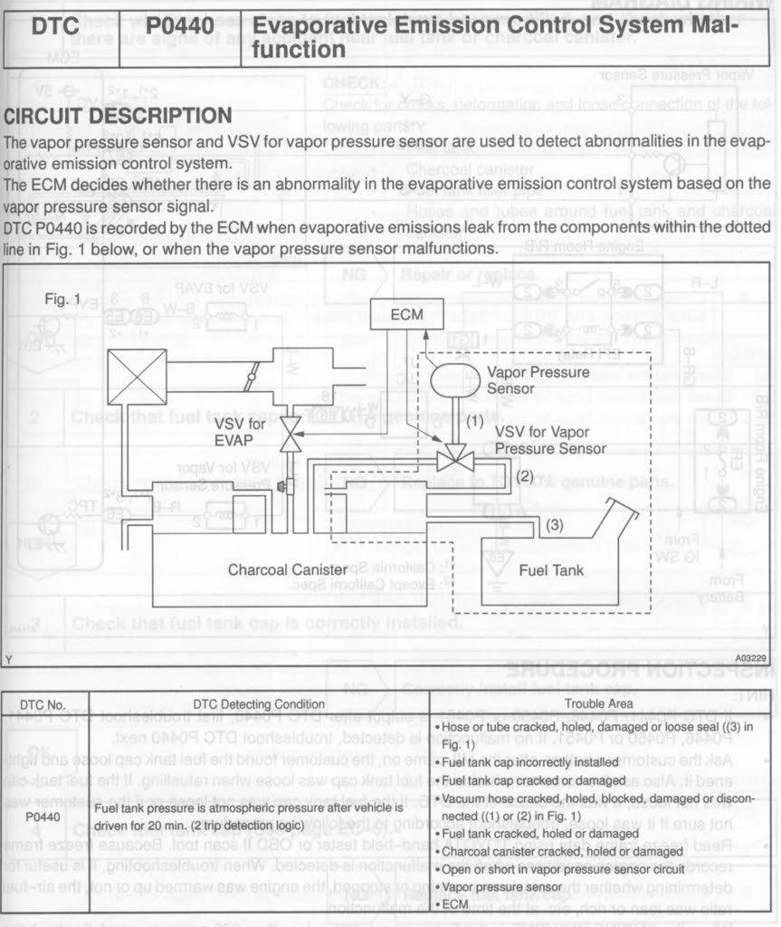 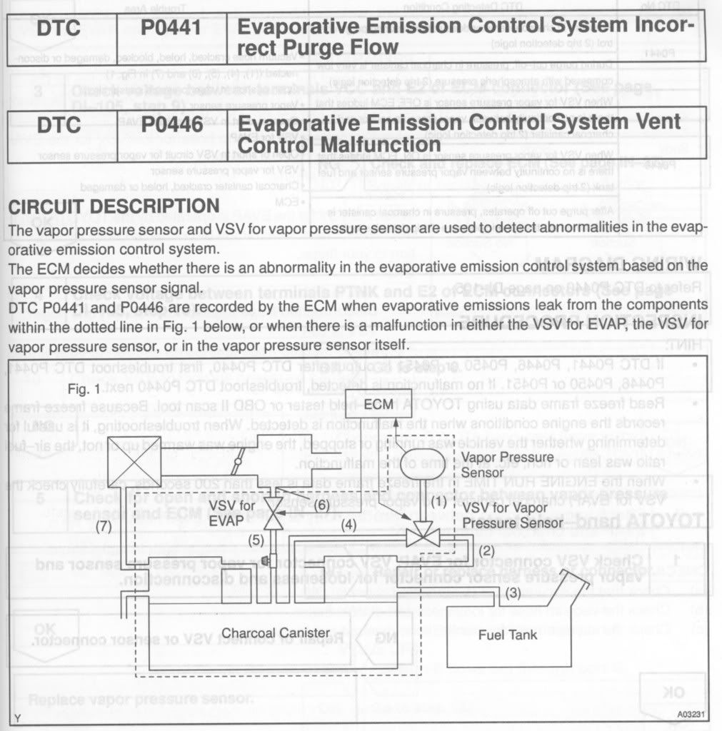 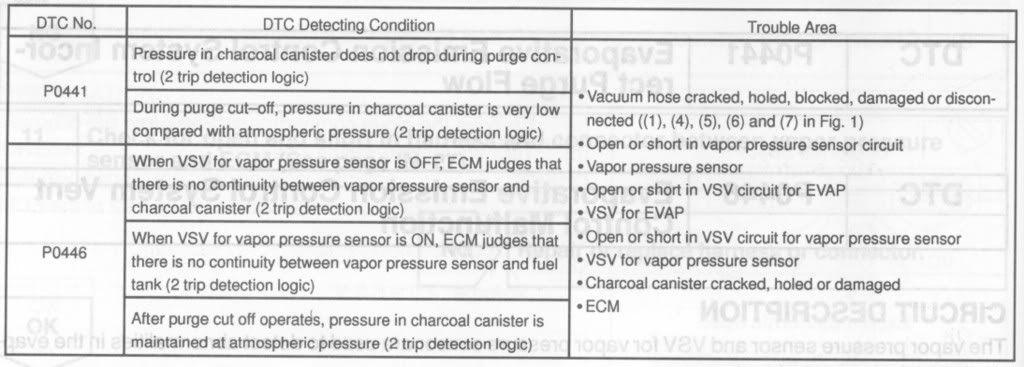 P0770 Shift Solenoid E Malfunction Solenoid E (SL) is the torque converter lock-up solenoid. If the torque converter is a little slow locking up, it will set this code. May only be a one-time thing owing to a small particle of something getting jammed in the solenoid. The code may disappear by itself. If it doesn't right away, check out the color of your tranny fluid. If it is pretty much red or brown and smells ok, then flush the tranny and see if that gets rid of the code. If not, pull out some fluid and add a bottle of Seafoam Trans Tune and run it for 1 or 2k miles. Then flush the transmission again. Check if the code is gone. If this problem persists, I've been told you'll have to replace the E-solenoid. There is a Service Bulleting (EG006-00) issued for '00 Siennas on this problem. They get a new torque converter to fix the problem permanently. The following discussion was submitted by csaxon: The ECM uses signals from throttle position sensor, airflow meter and crankshaft position sensor to monitor engagement of Torque Converter Clutch (TCC). The ECM compares engagement condition of TCC with lock-up schedule in memory to detect MECHANICAL trouble of lock-up solenoid, valve body and torque converter. A P0700 trouble code is set when TCC lock-up does not occur during appropriate speed, or lock-up does not release at appropriate speed. Possible causes are: * Solenoid is stuck open or closed. * Valve body clogged or valve stuck. * TCC malfunction. There are simple electrical tests to check the solenoid and plunger but the transmission pan must be removed to gain access. As Brian suggests, if you haven't had your system flushed or changed in awhile it may help but I'm not sure that's cheaper than actually removing the pan and checking the solenoid. The Toyota service tech can check the system without pan removal with his analyzer. P0793 "Intermediate Shaft Speed Sensor A" Thanks to hk rogers for the following information: Recently had a repair on a 2009 Toyota Matrix 2.4L with a CEL P0793 "Intermediate Shaft Speed Sensor A" code that I had a lot of difficulty finding good information on. Thought I'd post the repair info here to help out others in the future. 1. I pulled the codes at Autozone and they told me I needed a Transmission Speed Sensor (Part #SU40465) however they were unsure the location and that there were 2 sensors and no way to tell which is bad. 2. Took code to Toyota Dealership and they tried to sell me an ABS Wheel Speed Sensor for $250. 3. After digging through a variety of online resources I suspected Autozone was correct, ordered the part and set out to find the sensor. 4. On the 2.4L Matrix both sensors are located beneath the Air Filter box. Disconnect the intake hoses, pull off the box, loosen the three bolts holding on the box and voila you have access. The "A" Sensor is located directly beneath the air box in a vertical position. The other Sensor ("B" I assume) is a little further forward and angled toward the back of the battery. I would imagine the battery would have to be removed for ease of access. 5. 1 12mm Bolt and a rather sticky wiring harness later and you're in business. P1780 PNP Switch Malfunction Easiest solution: It is common on Camrys to have problems with the loom of wires inside the trunk, attached to the driver's side trunk hinge. That loom is subjected to a lot of flexing, each time the trunk opens and closes. Eventually some of the wires inside that loom fray and break. Open that loom of wires and look for frayed or broken wires. Repair what you find. For pics see here. Thanks to Mike Gerber For further diagnosis: http://www.automotiveforums.com/vbul...d.php?t=504073
__________________
Forum Guidelines:http://www.automotiveforums.com/vbulletin/guidelines.html "What we've got here is a failure to communicate" Last edited by Brian R.; 08-30-2019 at 12:11 PM. |
|
|
|
| The Following User Says Thank You to Brian R. For This Useful Post: |
yatri25 (05-14-2011)
|
|
06-30-2005, 04:16 PM
|
#22 | |
|
Resident Chemist
Join Date: Feb 2004
Location: Rockville, Maryland
Posts: 8,586
Thanks: 105
Thanked 157 Times in 157 Posts
|
Re: Camry FAQs and Information
HALF-SHAFT REPLACEMENT
Thanks Erndog1396 Q: I have a torn CV boot. What is the best way to fix it? A: Buy a remanufactured axle. Remove the large CV boot clamp just to the outside of the innermost bearing. Pull the inner joint apart, and when you get the new axle, do the same thing, and install the new half shaft and replace the clamp. This is the easiest way to do it, and you will still replace all the wearable parts of the axle. ASM used the following alternative method: "...The secret is to use a vary long brass punch, 24". Hold it against the raceway bearing and use a sludge hammer to hammer it out. This will require 2 people, as one must hold the punch and the other one work the hammer. What I also did was use A LOT of WD-40 (penetrating oil is better - Brian), and let it soak over night. When work the hammer, hit it hard, don't be shy. As most of replacement CV shaft came with new raceway bearing anyway." It is cheaper and less time consuming to replace the entire half-shaft with a rebuilt one than to dissassemble the half-shaft and CV joint, rebuild the contaminated CV joint, and then reassemble and install the half-shaft. http://www.automotiveforums.com/vbul...d.php?t=199055 Toyota-recommended procedures for removing and replacing the 1MZ-FE and 5S-FE half-shafts. 1MZ-FE http://i16.photobucket.com/albums/b8...Files/hs21.jpg http://i16.photobucket.com/albums/b8...Files/hs22.jpg http://i16.photobucket.com/albums/b8...Files/hs23.jpg http://i16.photobucket.com/albums/b8...Files/hs24.jpg http://i16.photobucket.com/albums/b8...Files/hs25.jpg http://i16.photobucket.com/albums/b8...Files/hs26.jpg http://i16.photobucket.com/albums/b8...Files/hs27.jpg 5S-FE http://i16.photobucket.com/albums/b8...Files/hs37.jpg http://i16.photobucket.com/albums/b8...Files/hs38.jpg http://i16.photobucket.com/albums/b8...Files/hs39.jpg http://i16.photobucket.com/albums/b8...Files/hs40.jpg http://i16.photobucket.com/albums/b8...Files/hs41.jpg http://i16.photobucket.com/albums/b8...Files/hs42.jpg For additional issues see the following threads: http://www.automotiveforums.com/vbul...d.php?t=348079 http://www.automotiveforums.com/vbul...d.php?t=362425 http://www.automotiveforums.com/vbul...d.php?t=324197 Toyota's procedure for rebuilding the 5S-FE half-shafts. http://i16.photobucket.com/albums/b8...DSRebuild1.jpg http://i16.photobucket.com/albums/b8...DSRebuild2.jpg http://i16.photobucket.com/albums/b8...DSRebuild3.jpg http://i16.photobucket.com/albums/b8...DSRebuild4.jpg http://i16.photobucket.com/albums/b8...DSRebuild5.jpg http://i16.photobucket.com/albums/b8...DSRebuild6.jpg http://i16.photobucket.com/albums/b8...DSRebuild7.jpg
__________________
Forum Guidelines:http://www.automotiveforums.com/vbulletin/guidelines.html "What we've got here is a failure to communicate" Last edited by Brian R.; 09-03-2005 at 12:29 PM. |
|
|
|
|
07-01-2005, 10:10 AM
|
#23 | |
|
Resident Chemist
Join Date: Feb 2004
Location: Rockville, Maryland
Posts: 8,586
Thanks: 105
Thanked 157 Times in 157 Posts
|
Re: Camry FAQs and Information
ENGINE PARTS LOCATION
Q: Where is my PCV valve? I have a 1997 LE V6 Camry and I have no clue. A: Try Autozone Repair Information - click on "Component Location": http://www1.autozone.com/servlet/UiB...epair_info.jsp GENERAL MAINTENANCE AND TECHNIQUES Q: What maintenance should I do on my Camry? I am not an accomplished mechanic, but I have tools and can do simple stuff, given some instructions. Any hints and general information for guys like me? A: Here are instructions for recommended maintenance on a 3rd gen Camry. Other generation Camrys may differ slightly, but the concepts and techniques are the same and the specific requirements are very close to general information for all Toyotas. 1MZ-FE 3.0L V6 http://i16.photobucket.com/albums/b8...ce/Maint15.jpg http://i16.photobucket.com/albums/b8...ce/Maint16.jpg http://i16.photobucket.com/albums/b8...ce/Maint17.jpg http://i16.photobucket.com/albums/b8...ce/Maint18.jpg http://i16.photobucket.com/albums/b8...ce/Maint19.jpg http://i16.photobucket.com/albums/b8...ce/Maint20.jpg http://i16.photobucket.com/albums/b8...ce/Maint21.jpg http://i16.photobucket.com/albums/b8...ce/Maint22.jpg http://i16.photobucket.com/albums/b8...ce/Maint23.jpg http://i16.photobucket.com/albums/b8...ce/Maint24.jpg http://i16.photobucket.com/albums/b8...ce/Maint25.jpg http://i16.photobucket.com/albums/b8...ce/Maint26.jpg http://i16.photobucket.com/albums/b8...ce/Maint27.jpg http://i16.photobucket.com/albums/b8...ce/Maint28.jpg http://i16.photobucket.com/albums/b8...ce/Maint29.jpg 5S-FE 2.2L I4 http://i16.photobucket.com/albums/b8...ce/Maint01.jpg http://i16.photobucket.com/albums/b8...ce/Maint02.jpg http://i16.photobucket.com/albums/b8...ce/Maint03.jpg http://i16.photobucket.com/albums/b8...ce/Maint04.jpg http://i16.photobucket.com/albums/b8...ce/Maint05.jpg http://i16.photobucket.com/albums/b8...ce/Maint06.jpg http://i16.photobucket.com/albums/b8...ce/Maint07.jpg http://i16.photobucket.com/albums/b8...ce/Maint08.jpg http://i16.photobucket.com/albums/b8...ce/Maint09.jpg http://i16.photobucket.com/albums/b8...ce/Maint10.jpg http://i16.photobucket.com/albums/b8...ce/Maint11.jpg http://i16.photobucket.com/albums/b8...ce/Maint12.jpg http://i16.photobucket.com/albums/b8...ce/Maint13.jpg http://i16.photobucket.com/albums/b8...ce/Maint14.jpg COMMENTS AND ADDITIONAL INFORMATION ON ABOVE RECOMMENDATIONS What Brand of Air Filter Performs Best? Here is a study of a number of brands of air filters: http://www.bobistheoilguy.com/airfilter/airtest1.htm http://home.usadatanet.net/~jbplock/ISO5011/SPICER.htm Power Steering Fluid Change Here is a procedure from toyotanation with pics: http://www.toyotanation.com/forum/t19334.html Spark Plug Change http://www.automotiveforums.com/vbul...d.php?t=419457 Use only Toyota-recommended spark plugs. Since the heads on both the above engines are aluminum, you must coat the spark plug threads with a small amount of anti-seize compound before you install them. Start threading the spark plugs by using a rubber hose pushed over the insulator of the spark plug so that you don't accidentally damage the threads in the head. If one doesn't go in easily, back it out and try again. Don't force them. Cross-threading the spark plug holes will eventually cost you money. Oil Weight Recommendation Use 5W-30 oil under all conditions unless you live in Arizona, Southern Texas, Fargo, etc. There is a significant benefit to getting the oil flowing immediately after start-up. Replacing Engine Coolant. Make sure you get all the air out of the system before you cap the radiator. Run the engine at idle with the radiator cap off and add coolant as necessary to keep the radiator full of coolant. Once the engine reaches operating temperature and the coolant begins to overflow, replace the radiator cap and fill the coolant reservoir to the hot line. Check the coolant level in the reservoir after the next time you drive it and it has had a chance to cool down. Valve Clearance Adjustment In general, you don't have to adjust the valve clearances in these engines unless you have modified the valve train in some way. Leave well-enough alone unless you have a specific need. Drive Shaft Boots Preventive Maintenance Spray them with silicone lubricant (WD-40 has also been recommended to me) every time you are under the car for an oil change. This will prevent them from drying out and they will last forever. Cracked and leaking boots are common after 6-8 years without some treatment and replacing the half-shafts because of this is expensive. Replacing Transmission Fluid It is preferable to flush the transmission and replace all the fluid this way, rather than just draining the small amount of fluid in the pan. The vast majority of the transmission fluid is trapped in the torque converter and the valve body and is not changed by draining the pan only. I have been told that it is unnecessary to change the filter in the transmission. It is wire mesh and only meant to keep chunks of stuff out of the valve body. If your serious about transmission maintenance, try this link for parts and transmission repair manuals: http://www.drivetrain.com/autotransoverhaulkits.html General Maintenance Always use a torque wrench to tighten fasteners to the recommended torque value. A pair of torque wrenches (one large and one small) are indespensible for auto maintenance, particularly when you have an aluminum engine/head. Two torque wrenches I recommend (or their equivalent) are: http://www.sears.com/sr/javasr/produ...&vertical=TOOL http://www.sears.com/sr/javasr/produ...id=00944593000 These are micrometer-style torque wrenches. You dial in the required torque and then the wrench clicks strongly when you exert the force necessary to tighten the bolt. To keep their accuracy, store them with the torque setting on a very low value. You can pay alot more for better wrenches, but these are more than adequate. Evenness of torque around a bolt pattern is more important that the actual torque value of the pattern. Don't extend the lever arm of a torque wrench with a crow's foot or other device. If you make the socket end of the torque wrench longer, you increase the torque applied to the bolt. If you have to use a lengthening adapter, use it at a 90 degree angle to the torque wrench shaft. Also, always make sure you are tightening a bolt or nut with lubricated threads (oil for steel hole, antiseize compound for aluminum hole). Bolts always have to go into clean holes. Run a flat-bottom tap into all holes that won't accept a bolt hand-tight to the bottom. Follow tightening sequences when provided - tighten gradually in three steps 1/3, 2/3, then recommended torque over entire bolt pattern. Tighten bolts in a bolt pattern only loosely until all the bolts have been inserted and are threaded into the holes. If you tighten some down prematurely, it will be very difficult or impossible to insert all the bolts and you will have to loosen the tight bolts anyway.
__________________
Forum Guidelines:http://www.automotiveforums.com/vbulletin/guidelines.html "What we've got here is a failure to communicate" Last edited by Brian R.; 04-01-2013 at 04:51 PM. |
|
|
|
|
07-01-2005, 09:43 PM
|
#25 | |
|
Resident Chemist
Join Date: Feb 2004
Location: Rockville, Maryland
Posts: 8,586
Thanks: 105
Thanked 157 Times in 157 Posts
|
Re: Camry FAQs and Information
GETTING RID OF BINDING STOCK ANTENNA
Q: My trunk keeps hitting my antenna since it won't go down the way it should. Is there a cheap fix for this? A: Some guys install a Honda S2000 antenna in place of the stock one. See this article: http://www.toyotanation.com/forum/t65507.html HAZY HEADLIGHT COVERS Q: My headlight covers are so hazy, I had to buy HID lights just so I would have enough light to drive buy. What can I do to polish them? A: See the solutions posted in this thread: http://www.automotiveforums.com/vbul...d.php?t=230436
__________________
Forum Guidelines:http://www.automotiveforums.com/vbulletin/guidelines.html "What we've got here is a failure to communicate" Last edited by Brian R.; 07-19-2005 at 12:11 PM. |
|
|
|
|
07-01-2005, 10:52 PM
|
#26 | |
|
Resident Chemist
Join Date: Feb 2004
Location: Rockville, Maryland
Posts: 8,586
Thanks: 105
Thanked 157 Times in 157 Posts
|
Re: Camry FAQs and Information
KNOCKING, THUMPING, OR CREAKING SOUND IN REAR/FRONT WHEN GOING OVER BUMPS
Q: I have been dealing with this weird noise for some time. I can hear the noise sounds like two pieces of heavy metal hitting each other. It sounds from the right rear area. It happens more often when speed is low say 30 mph on rough road. On highway, it does not happen as often. Anyone know what it can be? A: First thing to check is your sway bar (stabilizer bar) bushings. What causes the bushings to wear is when water and salt (or just water) gets into the bushing, it corrodes the surface of the sway bar and the surface becomes rough. This wears away the bushing. To get a long-term fix, you should polish the sway bar with a strip of emory cloth where the bushing rubs and then replace the bushing with a new one. Then the sway bar is smooth and the fix will last longer. If there is nothing loose (including the spare tire and jack) in the trunk, then the sway bar bushings are the first thing to check/replace. They are cheap to buy from Toyota ($10/pair) and easy to replace - 30 min at most. When I have bought bushings from Toyota, they even gave me a strip of emory cloth to polish the bar with. Here's a thread on the subject: http://www.automotiveforums.com/vbul...3&page=1&pp=15 Here are the components: 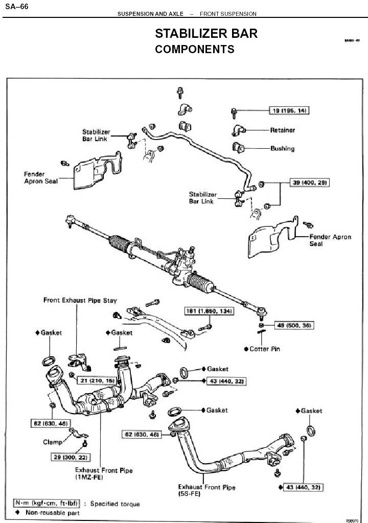 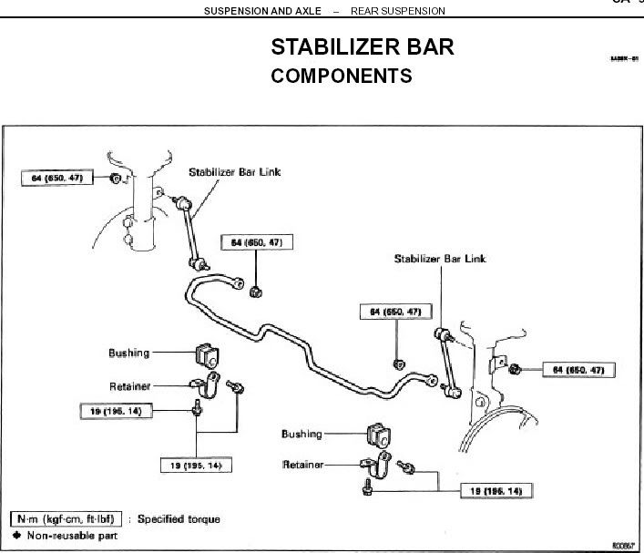
__________________
Forum Guidelines:http://www.automotiveforums.com/vbulletin/guidelines.html "What we've got here is a failure to communicate" |
|
|
|
|
07-02-2005, 01:56 PM
|
#27 | |
|
Resident Chemist
Join Date: Feb 2004
Location: Rockville, Maryland
Posts: 8,586
Thanks: 105
Thanked 157 Times in 157 Posts
|
Re: Camry FAQs and Information
CAR RUNS POORLY AT STOP LIGHT AND WANTS TO DIE
Q: My car starts good, runs ok going down the highway, but at a light it runs like poo-poo and wants to cut out. Any suggestions? A: I'll bet your EGR valve is clogged. To check: Get a common hammer, locate the EGR, make it run bad, rap the EGR with the hammer (don't break it). You should be able to get the valve to unstick and it will idle like magic! Clean out the EGR with a coat hanger and carb cleaner or replace. http://www.automotiveforums.com/vbul...d.php?t=375652 http://www.automotiveforums.com/vbul...d.php?t=201333 http://www.automotiveforums.com/vbul...d.php?t=280858 http://www.automotiveforums.com/vbul...d.php?t=194096
__________________
Forum Guidelines:http://www.automotiveforums.com/vbulletin/guidelines.html "What we've got here is a failure to communicate" |
|
|
|
|
07-02-2005, 11:27 PM
|
#28 | |
|
Resident Chemist
Join Date: Feb 2004
Location: Rockville, Maryland
Posts: 8,586
Thanks: 105
Thanked 157 Times in 157 Posts
|
Re: Camry FAQs and Information
FUEL FILTER LOCATION AND REMOVAL INSTRUCTIONS FOR '92 - '96 CAMRY
Q: Does anyone know where the fuel filter is located on a 4 cyl 95 Camry? Is it easy to change? Thanks! A: It is bolted to the wheel well behind the air filter housing. It is easy to change if you have small hands. Before you disconnect any fuel lines, go under the rear seat - access the top of the gas tank, and disconnect the fuel pump electrical connection. Start the engine and let it idle until it dies, then shut off the ignition switch. Disconnect the negative battery terminal. Then follow the diagram below. The fuel filter is removed physically by unbolting from the fender. Use a tubing wrench (or crows foot) instead of either an open-end wrench or adjustable jaw wrench to remove tubing connections. Use penetrating oil on the fitting first to help remove it. They are soft metal and easily rounded off if you are not careful. Instead of a crows foot, a box-end wrench with a slot cut out of one end will work in a pinch. Be careful not to twist the tubing when tightening or loosening a tubing fitting. 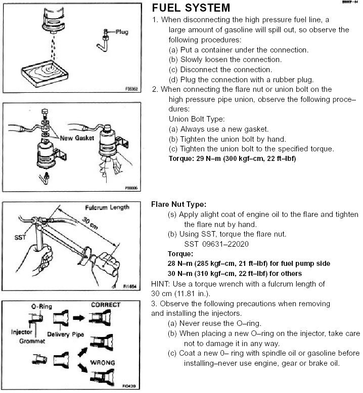
__________________
Forum Guidelines:http://www.automotiveforums.com/vbulletin/guidelines.html "What we've got here is a failure to communicate" Last edited by Brian R.; 07-27-2005 at 10:34 PM. |
|
|
|
|
07-10-2005, 08:10 PM
|
#29 | |
|
Resident Chemist
Join Date: Feb 2004
Location: Rockville, Maryland
Posts: 8,586
Thanks: 105
Thanked 157 Times in 157 Posts
|
Re: Camry FAQs and Information
REBUILDING YOUR OWN ALTERNATOR
Q: My brake and charge lights come on at the same time when the engine is running. What does that mean? A: If the brake and charge lights come on during revving of the engine then it's a sign that the carbon alternator brushes require replacing as this is the mileage for them to wear out. In alternators the brushes wear out on average every 140-170 000 miles where on the dashboard the brake & charge light both come on at the same time. About half of the auto electric shops in your local yellow pages sell carbon alternator brushes and copper solenoid starter contacts for about $5/pair.Another way to verify that the alternator is not charging is while the engine is running bring a metal screwdriver or any metal object near the alternator and if the alternator is working properly then it should act like a magnet and grab the screwdriver. For carbon brushes R&R: http://www.4x4wire.com/toyota/mainte...nator_brushes/ http://www.toyotaoffroad.net/afertig...torbrushes.htm http://perso.wanadoo.fr/adherence.4x...nateur_kzj.htm http://www.automotiveforums.com/vbul...d.php?t=166525 http://www.toyotanation.com/forum/sh...270&forumid=10 http://www.pirate4x4.com/forum/showt...r+brush+holder http://www.bitwalla.com/cruisers/art...lternator.html http://www.barneymc.com/toy_root/tec...c/altrnatr.htm For decoding the dashboard lights: http://www.powerbase-auto.co.uk/alternator_faults.htm http://members.1stconnect.com/anozir...alternator.htm Here are part #'s for Toyota alternator carbon brushes and copper solenoid starter contacts which are used in about 95% of all Toyota vehicles. Toyota alternator Brushes with holder: Toyota # 27370-35060=$29 CDN Honda # 31105-PZ1-003 Metro # 39-82003 (www.metroautoinc.com ,Pomona,California) Unknown brand name # F4019-53035 Alternator brush only (qty:1 brush unless otherwise stated): AC Delco # E724 AC Delco # E731 (side wire and concave tip) Ace Electric # DA-61 (brush only),S-5367 (brush holder) Beck Arnley # 178-1669 (side wire and concave tip) Beck Arnley # 178-1376 Borg Warner # X580 (side wire and concave tip) Canadian Tire # 19-2050-6=$4.49/pair Daihatsu # 27370-87302-000 Daihatsu # 27371-63020-000 Daihatsu # 27371-87501-000 Daihatsu # 27371-70300-000 Echlin # E601=$8.16 CDN/pair (UAP/NAPA) Echlin # ECHE601 Echlin # EC480 Echlin # ECHE480 GP Sorensen # 255047 (side wire and concave tip) GM # 94123056 GM # 96054118 Honda # 31144-PD1-004=$9.72 Honda # 31144-PD1-0040 Honda # 31144-PD1-0030 Honda # 31150-PR7-A01 Honda # 31150-PTO-003 Hino Industries # 021660-0390 Hino Industries # 021660-0510 Isuzu # 8-94123-056-0 Isuzu # 8-97032-308-0 Isuzu # 8-97032-310-0 Mazda # 021660-0390 Mazda # 021660-0510 Mazda # KL47-18-W75 Metro # 38-82001(side wire concave tip) (www.metroautoinc.com ,Pomona,California) Mileage Plus # E601SB Mitsubishi # MD604474 Mitsubishi # 21660-0510 Niehoff # WA571 (side wire and concave tip) NipponDenso # 021660-0390 NipponDenso # 021660-0510 Standard # JX-116 (side wire and concave tip) Subaru # 021660-0390 Subaru # 021660-0510 Suzuki # 31631-82610 Suzuki # 31656-82611 Suzuki # 021660-0510 Toyota # 27370-42010 Toyota # 27370-75060 Toyota # 27371-63020=$5.80 (up to 9105) (side wire and concave tip) Toyota # 27371-70300=$5.20 (9105-9511) Toyota # 27371-76004-71 UAP/NAPA # MPEE601SB Victory Lap # FAX57=$4.49 CDN/pair (Canadian Tire) Wilson's Electric # 26-29-7534 (side wire and concave tip)=$2.20 each CDN (Diesel Auto Electric)(Parts for Trucks, box of 10 for $3.40 CDN) Specifications: Length=15 mm Width=7 mm Thickness=5 mm Lead length=49 mm These Honda alternators are the same except the pulley must be swapped: 1986-89 Honda Accord (Carb),the EFI can be used but the voltage reg must be swapped 1990-93 Acura Integra Thanks to SydneyCanada for the above information
__________________
Forum Guidelines:http://www.automotiveforums.com/vbulletin/guidelines.html "What we've got here is a failure to communicate" Last edited by Brian R.; 11-10-2005 at 10:51 PM. |
|
|
|
|
07-12-2005, 11:47 PM
|
#30 | |
|
Resident Chemist
Join Date: Feb 2004
Location: Rockville, Maryland
Posts: 8,586
Thanks: 105
Thanked 157 Times in 157 Posts
|
Re: Camry FAQs and Information
MOBILE ELECTRONICS/STEREO INSTALLATION
Q: Where can I find information on how to install a new stereo in my Camry? A: The Install Doctor is a good source: http://www.installdr.com/ also see: http://www.autozone.com/servlet/UiBr...3d8013f150.jsp http://www.autozone.com/servlet/UiBr...3d8013fc58.jsp
__________________
Forum Guidelines:http://www.automotiveforums.com/vbulletin/guidelines.html "What we've got here is a failure to communicate" Last edited by Brian R.; 09-08-2005 at 03:18 PM. |
|
|
|
|
|
POST REPLY TO THIS THREAD |
 |
|
|

