|
|
|

|
|
| Search | Car Forums | Gallery | Articles | Helper | AF 350Z | IgorSushko.com | Corporate |
|
| Latest | 0 Rplys |
|
|||||||
| WIP - Motorsports Post topics for any "Work In Process" motorsports vehicles in this sub-forum. |
 |
 Show Printable Version | Show Printable Version |  Email this Page | Email this Page |  Subscribe to this Thread
|
|
|
Thread Tools |
 07-18-2020, 10:53 AM
|
#76 | |
|
AF Enthusiast
Thread starter
Join Date: Nov 2008
Location: Norwich
Posts: 649
Thanks: 21
Thanked 111 Times in 87 Posts
|
Re: 1/8 Porsche 956
...and back!
Hello everyone, First up, my lack of posts in recent weeks has not been in any way health-related. I returned to the workshop in mid-May, and once we got into June things just started getting busier and busier - we've had cars testing every week for the last five weeks, and our first race meeting last weekend. I've been making good progress with the 956, but started having issues uploading to Photobucket. It's taken a couple of weeks to get a response as to how to solve the problem, and hopefully things should be back to normal. The problem now is trying to remember exactly what I've been doing for the last couple of months! So, back when I was working on the front wishbones, I also made the initial components for the front dampers: 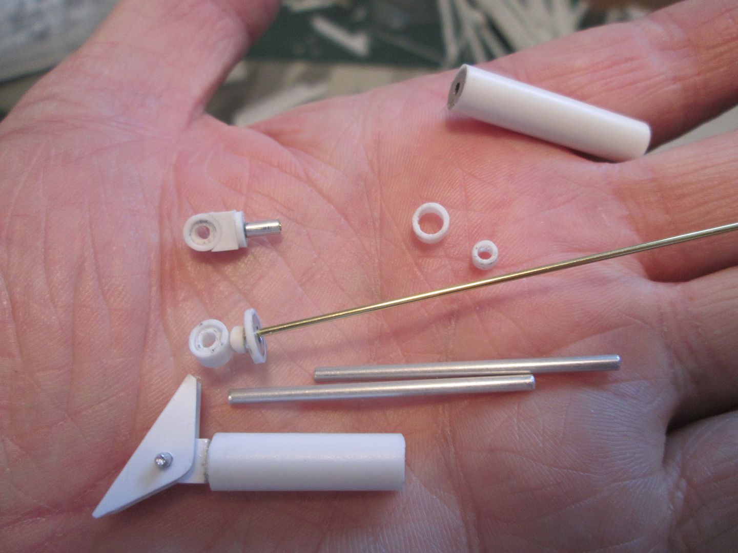 As usual it was a case of playing around with all the various sizes of brass rod and aluminium and styrene tube to have everything sliding properly, staying aligned, and being strong enough to survive. There's always a bit of juggling with getting the lengths right - allowing a bit of droop, providing enough compression on bump, and having it all looking right at ride-height. I still like to build my models with movement in the suspension - I'd hate everything to be fixed and then find one wheel kicked up in the air! At this stage I've made enough to be happy that they will work. The extra detailing - spring platforms, body threads, etc - can all happen later. The two front wishbones received outer skins of 0.4mm styrene and some greenstuff to fill in the gaps: 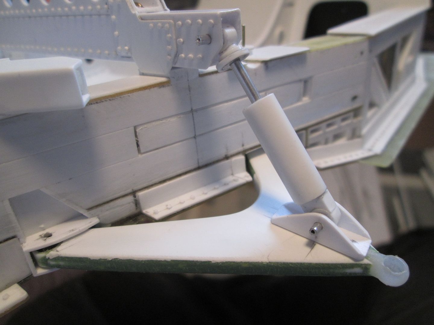 Since this photo the damper mounting brackets have been detailed with some reinforcing gussets and some greenstuff 'welding'. The wishbone pick-ups on the chassis have been drilled, so the whole lot can be set 'just so'. The next job was to make the front brake discs. Depending on which photo you find of which car in whatever year at whatever race, you'll see a mix of plain and drilled discs in use. While plain discs would be much easier to create, you know that I like making a mess with styrene! So, drilled and ventilated discs it would be. The pattern of holes in each side would be a sequence of three, three and two, repeated ten times. So, eighty holes per side, two sides per disc - a happy 320 holes to be marked, drilled and de-burred. And that's just for the fronts - I'll have to do the same later with the rears. To make life easier I made a simple template of the hole pattern, then marked the spacing on another piece of styrene sheet so that I could rotate the template around the disc: 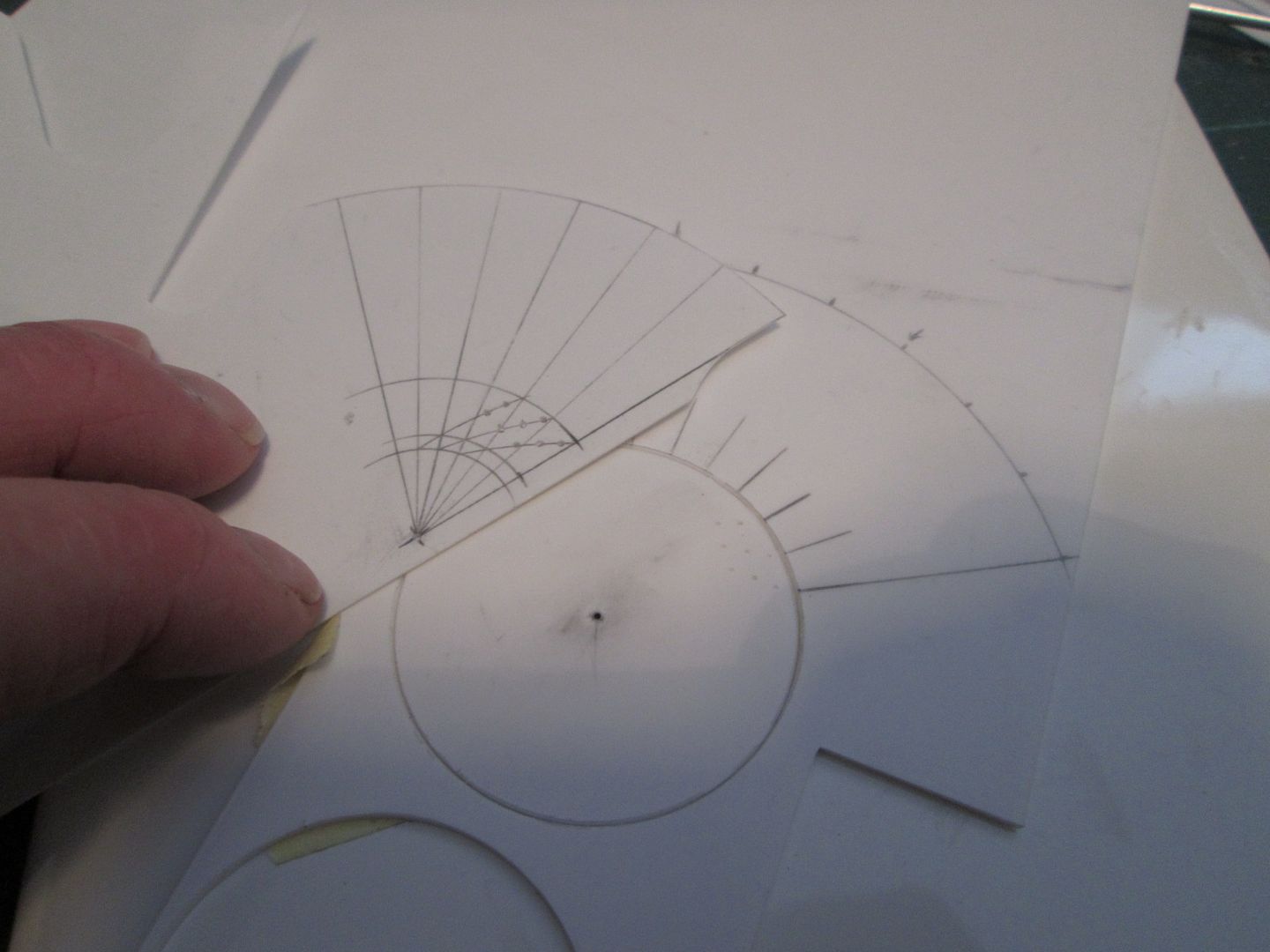 After making a lot of styrene swarf with the holes, I could fit the 1.5 x 1.5mm vanes to create the ventilated disc. The extra ten holes on the right-hand disc will match-up with the bell later: 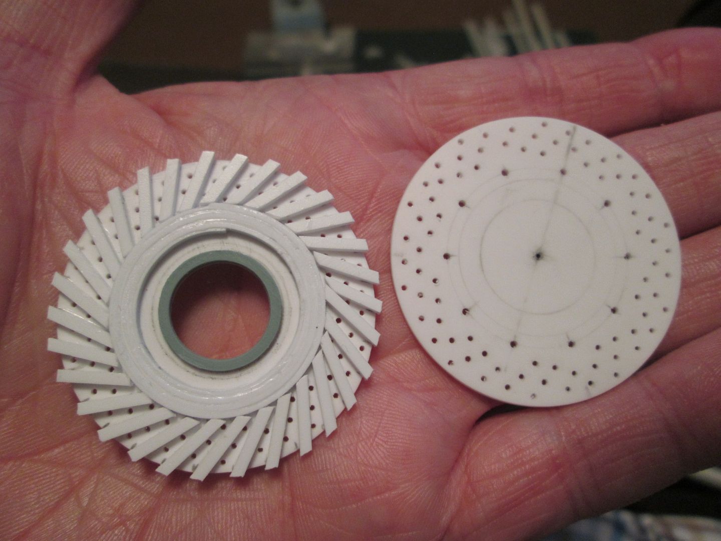 I painted the inner surfaces of the two sides before gluing everything together. The disc bells you see here will also eventually have a separate top cap which will trap the capscrew into the hub, and will also provide the seat for the wheels: 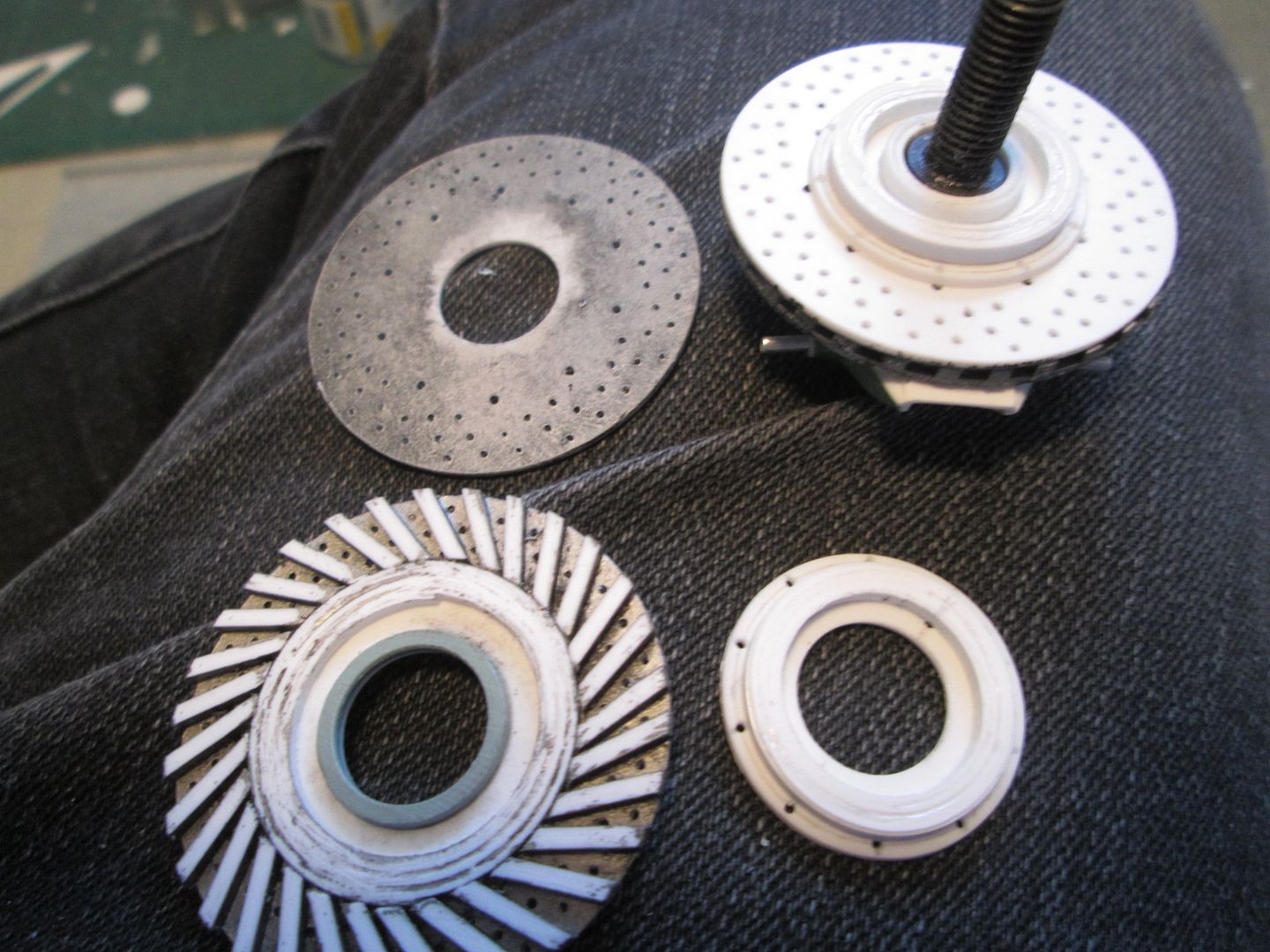 What's next? Before I could think about moulding the undertray bodywork I knew I had to finalise the position of the drivetrain. The original side-frames I'd made to suit the dummy cardboard tub were never intended to be used in the long-term, so it was now time to make the proper parts. I spent a good while making a Lego frame to support the engine and gearbox at the correct angle, keeping it square to the back of the tub: 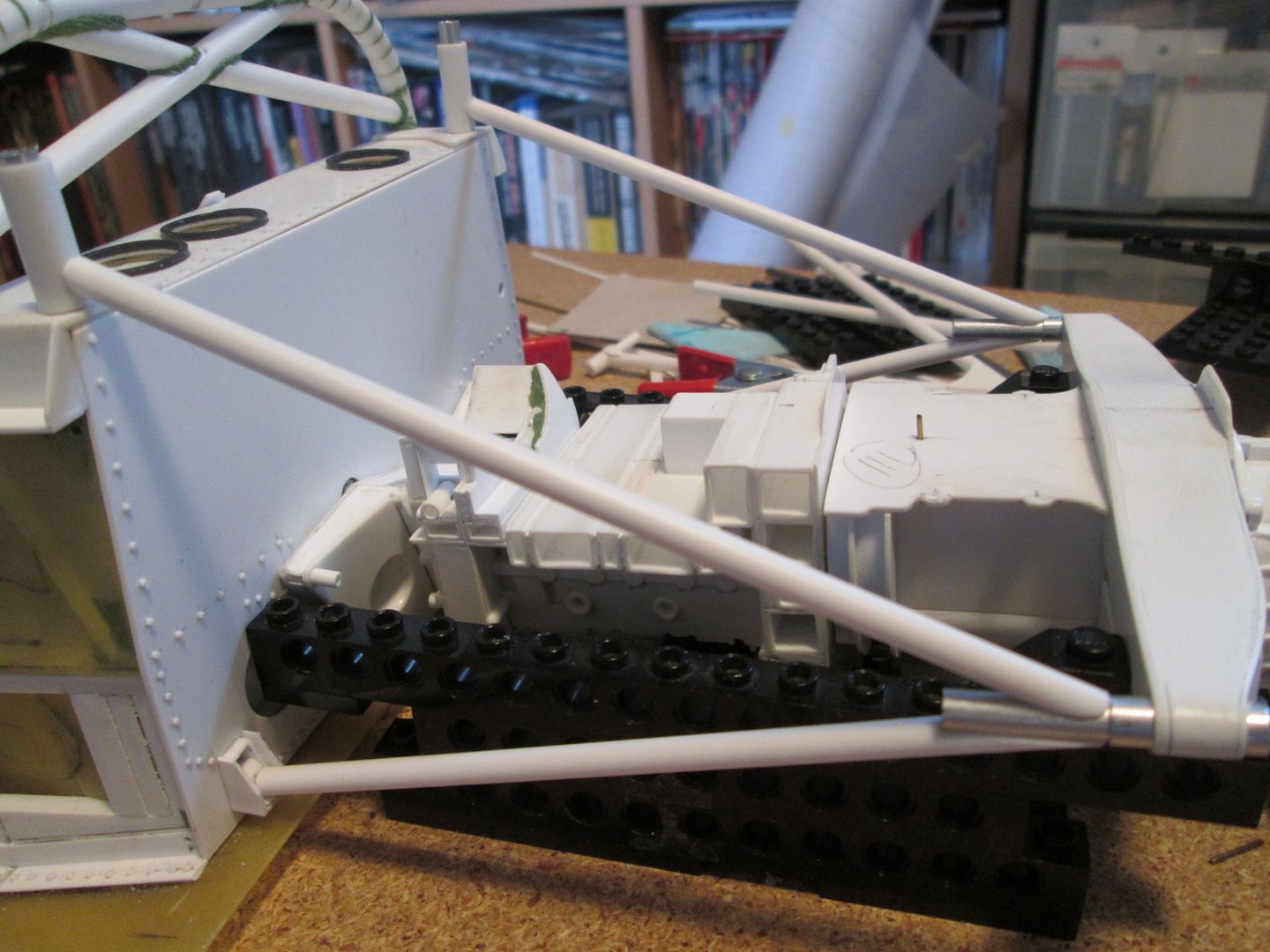 The main legs of the frames are 4mm styrene, with aluminium tubing up the inside, and the joints to the middle of the 'V' are heavily pinned. Strength is a big issue! You can't see the detail here, but the lower sockets into the bottom of the chassis tub have been made so that the legs pin through . The joints at the top of the tub were a little harder to create, but I managed to create a 'hook' which will give me a solid glued joint into the engine frame, and will also feed loads into the ali tubes I've hidden inside the tub: 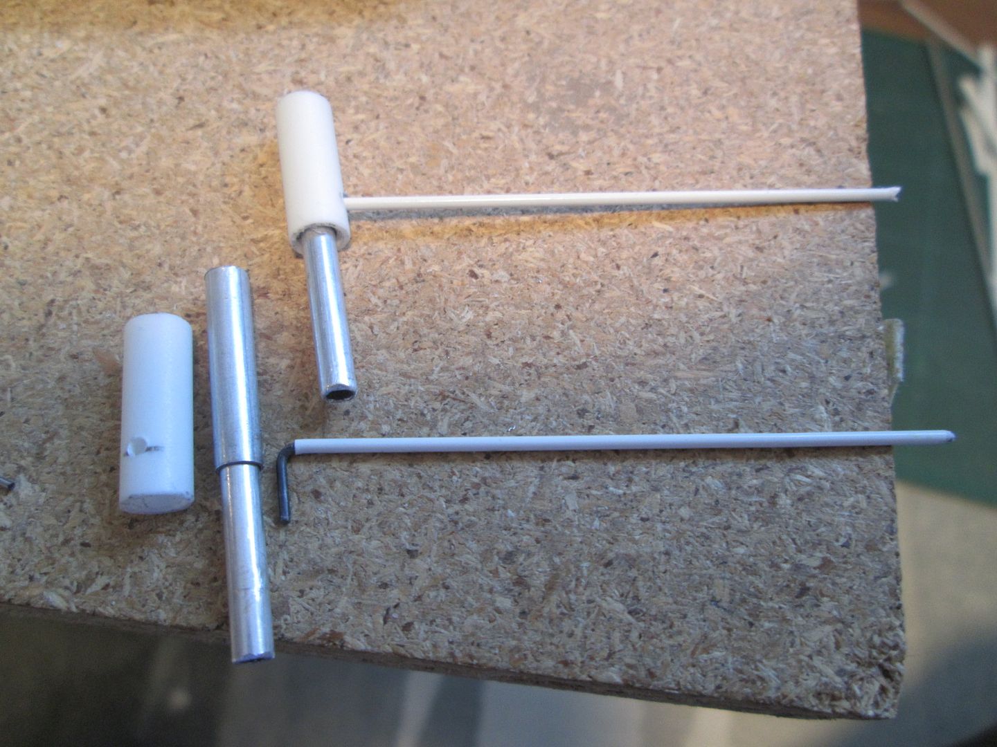 With these bits sorted out I could make the extra sections of roll-hoop: 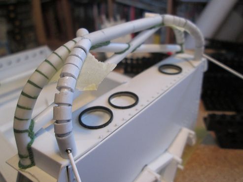 Next, I start making the undertray...but I'll cover that in the next post! Stay well, SB |
|

|

|
|
07-18-2020, 02:07 PM
|
#77 | |
|
Blarg! Wort Wort Wort!
Join Date: Mar 2006
Location: Quezon City
Posts: 2,120
Thanks: 64
Thanked 101 Times in 100 Posts
|
Re: 1/8 Porsche 956
great update!
...so, working brake caliper pistons? 
__________________
olly olly oxen free |
|
|
|
|
|
08-24-2020, 03:07 PM
|
#78 | |
|
AF Enthusiast
Thread starter
Join Date: Nov 2008
Location: Norwich
Posts: 649
Thanks: 21
Thanked 111 Times in 87 Posts
|
Re: 1/8 Porsche 956
Must update more often...must update more often!
Hello again, I didn't expect it to be another month between updates, but it's just the way things have been going recently. I keep thinking to myself 'I'll do a bit more then I'll update'...and another week goes by and it's 'I just need a couple more days to get this bit finished, then I'll update'...and so on. Then I forget why I took the photos I took, and realise I haven't taken all the photos I need to take! No problem - if I don't mention something you can see in any of the photos, I'm sure I'll get back to it eventually. First up - undertray. Looking at the photo info I seem to have spent most of June working on this - where did the weeks go? I started by marking out the basic reference points on my large board, then hotwiring two curved sections of foam to create the upsweep either side of the drivetrain: 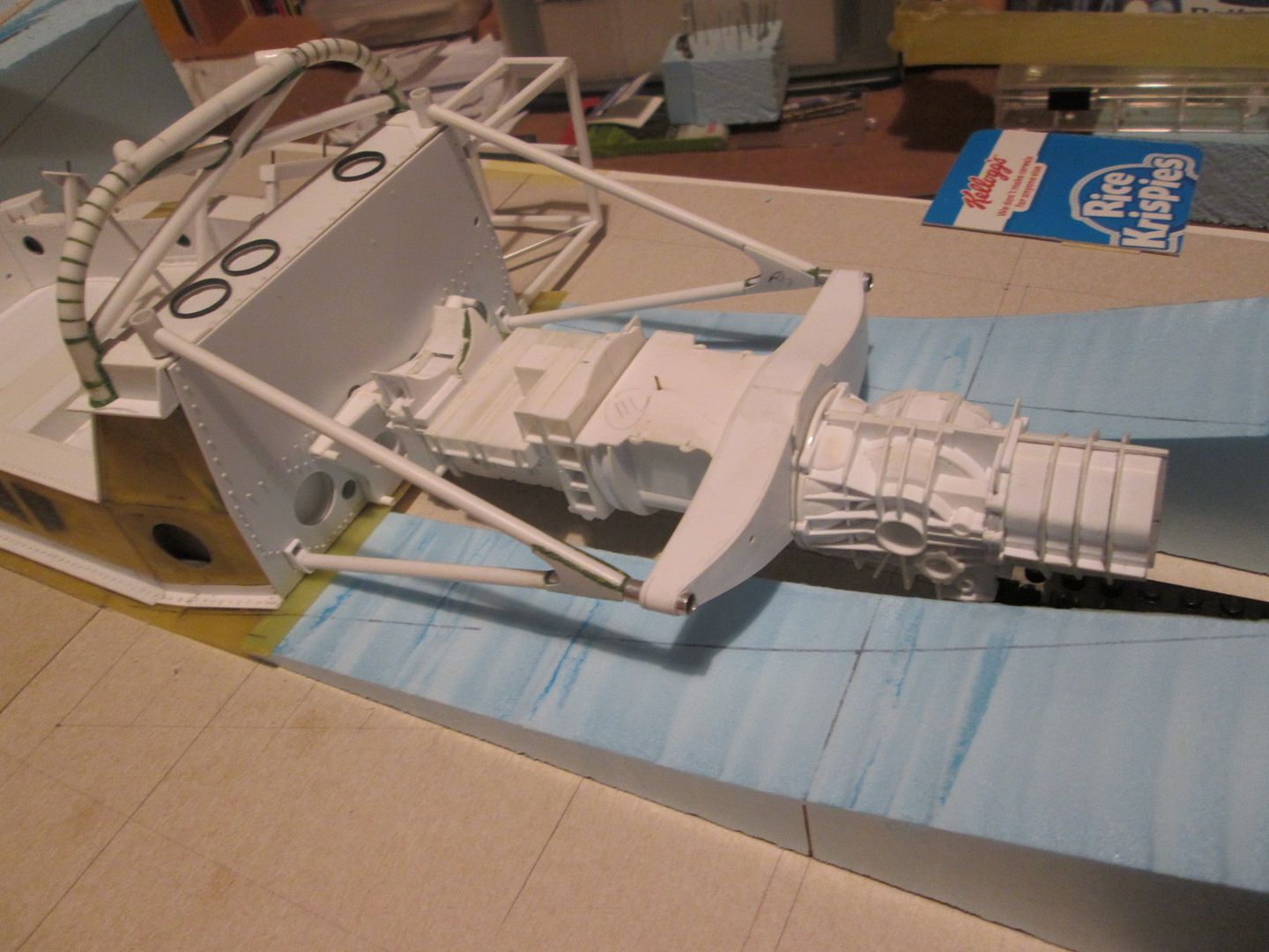 These first parts were then cut lengthwise, and another pair of sections added to create the main venturi tunnels: 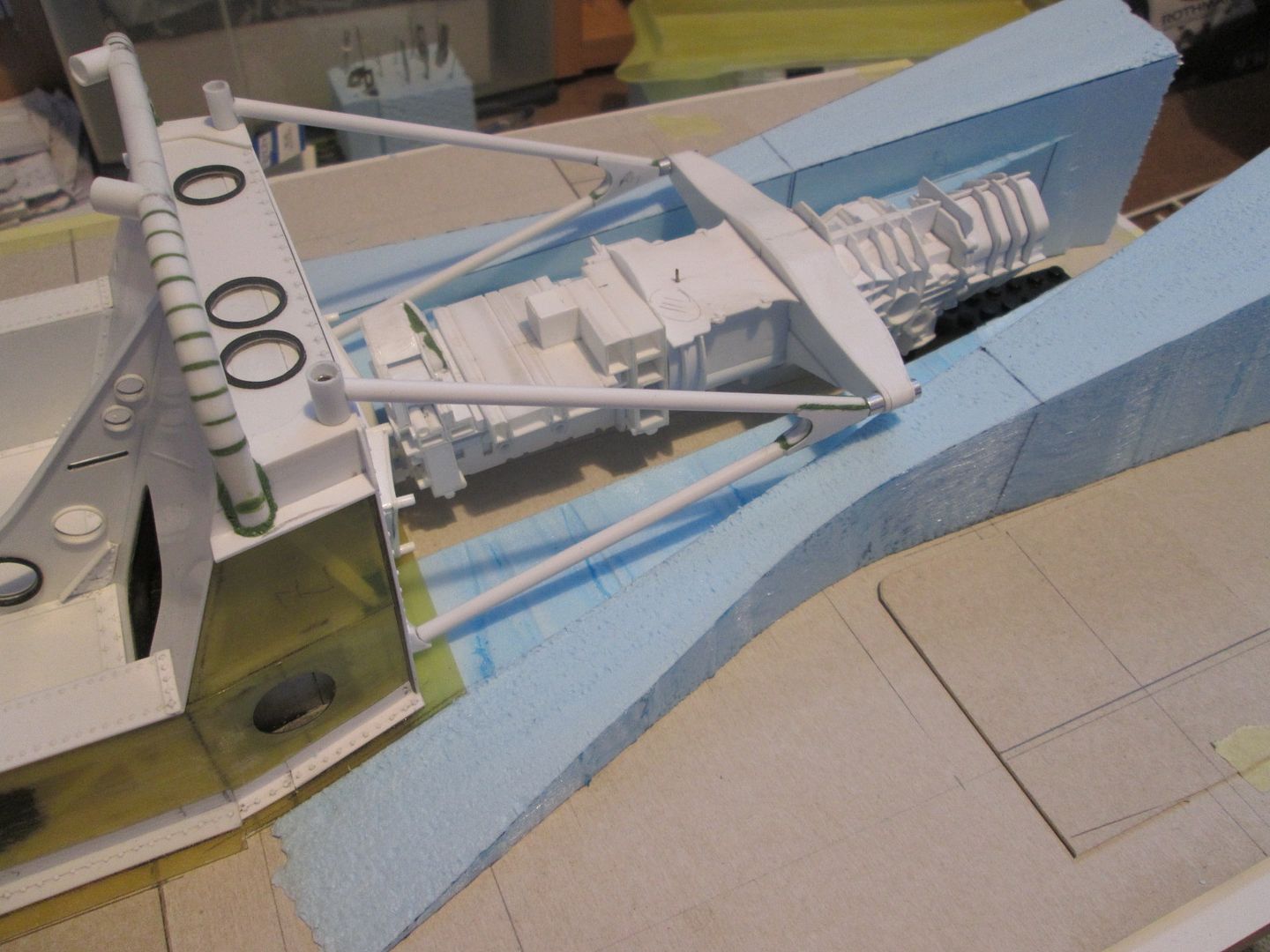 As you can see, the venturis and upward sweep of the undertray extend forwards of the engine bay - hence the angled underside of the back of the chassis, and the step in the radiator support frames. With a bit more foam, some balsa strip, filler and some cardboard, I had this: 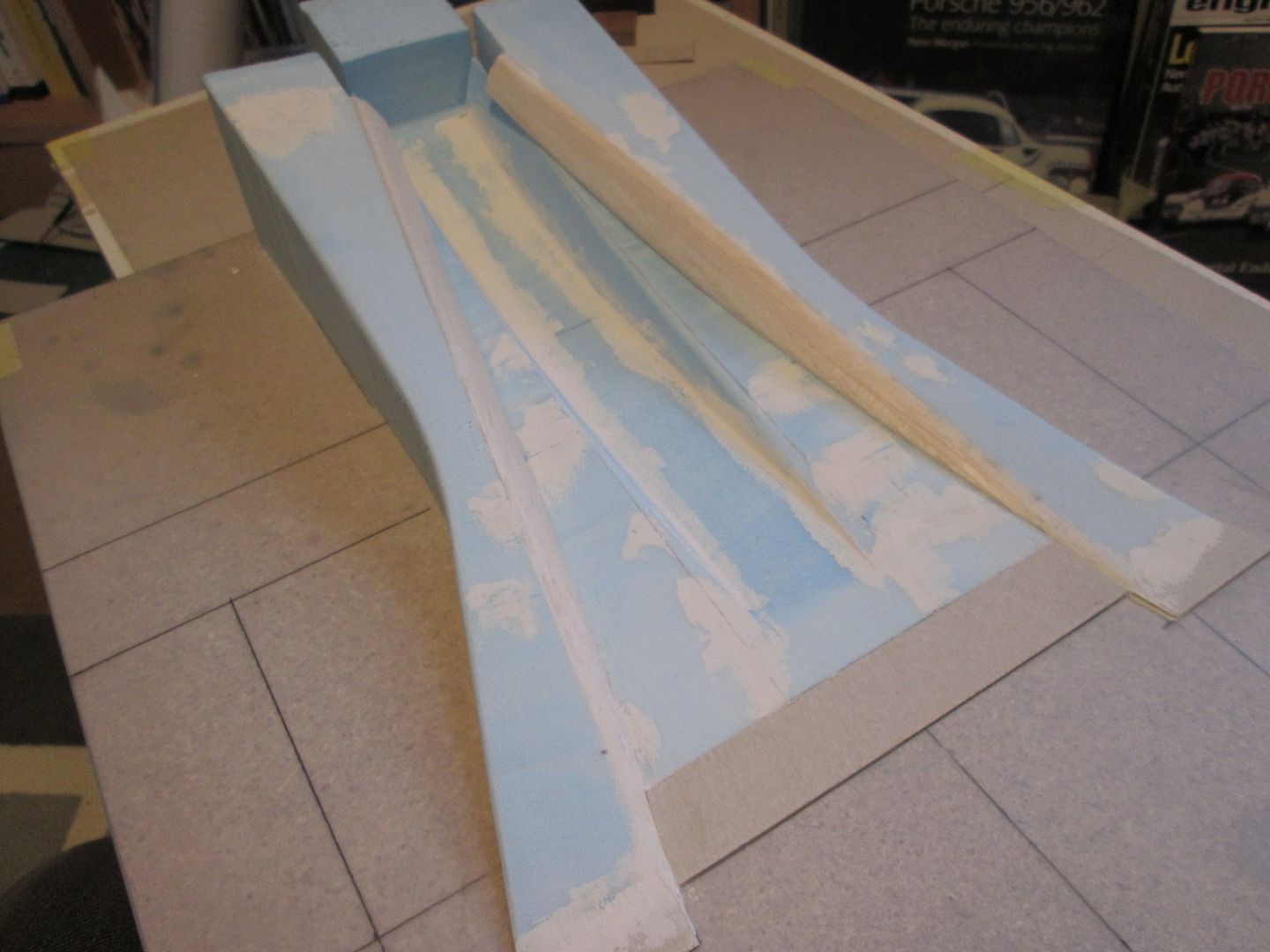 Yes, the far end by the back of the gearbox looks a bit rough - that's intentional. At this stage I didn't know exactly how long the gearbox was going to be, and I felt it would be too difficult to guess at the exact shape of this final section. My plan was to make the bulk of the undertray first, then make a second smaller mould just for the closing piece at the back. After a lot of cloth and a few nights work, I had this: 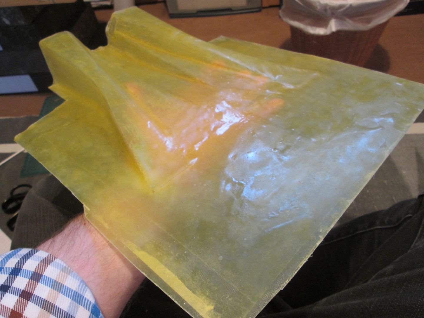 This was not as straightforward to make as it appears. It's the largest piece of fibreglass I've moulded since making the nose of the 935-78, and I couldn't put on a complete layer fast enough before the resin / hardener mix started going off in the pot! The large flat area under the cockpit was a help, but care had to be taken around the venturis to avoid the cloth lifting up and creating air bubbles. At this point I'm planning to leave the undertray as one complete section extending all the way forward under the cockpit - it'll save the problem of having to attach separate sidepods to the tub, and it helps to keep everything aligned at the back. A quick bit of trimming, and I could drop in the tub and drivetrain to check the fit: 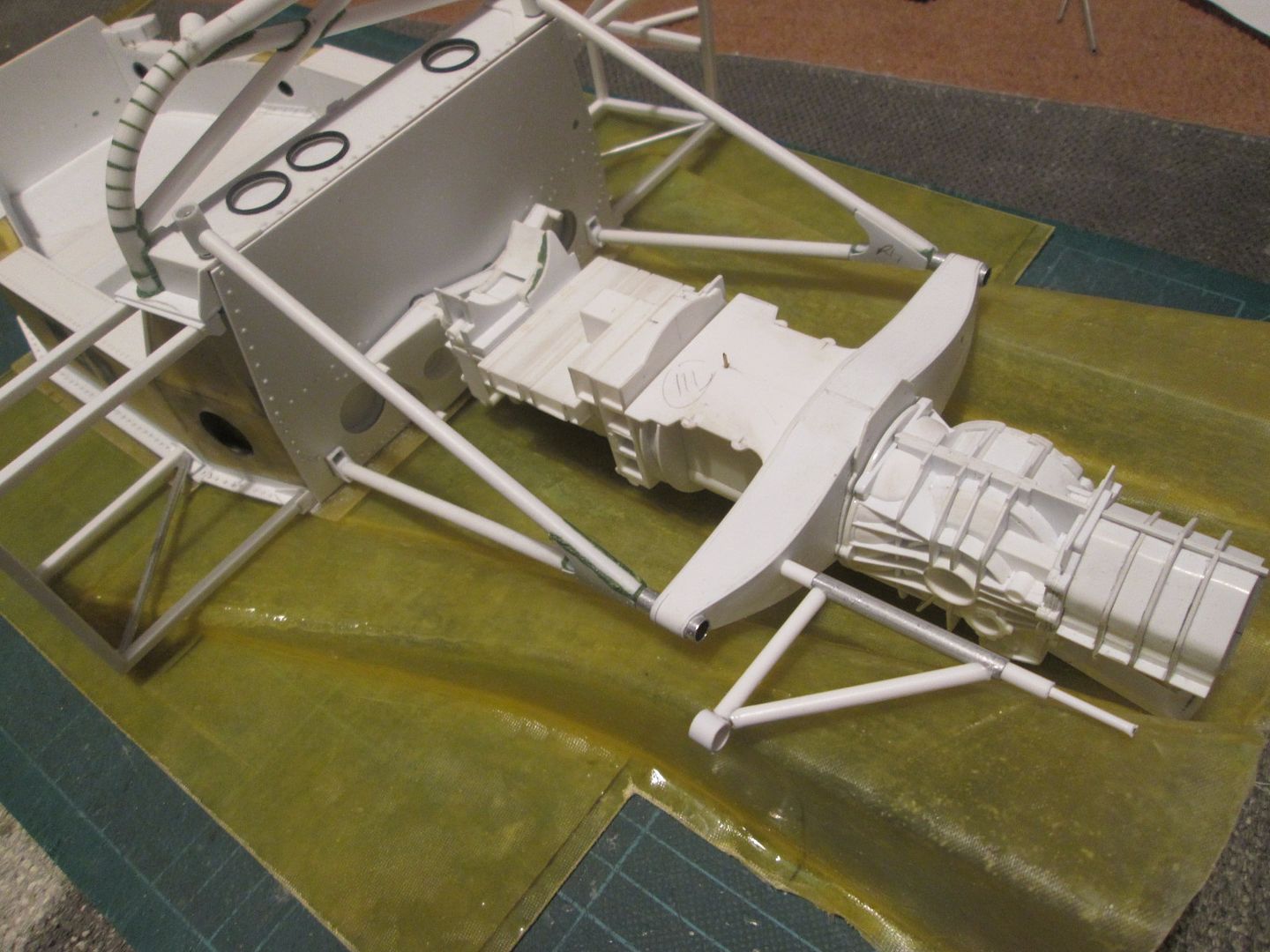 So far so good - nothing fouls, there's room to fit the exhaust pipes between the lower A-frame tube and the undertray to each side, and the rear top suspension arms sit above the venturi tunnels. It needs a lot more work before it's completed, but for now I'm pleased with how it's turned out. Next job was to start on the rear suspension - particularly the uprights and top wishbones. You can see that I'd made a start on the top wishbones in the photo above; here's a bit more progress: 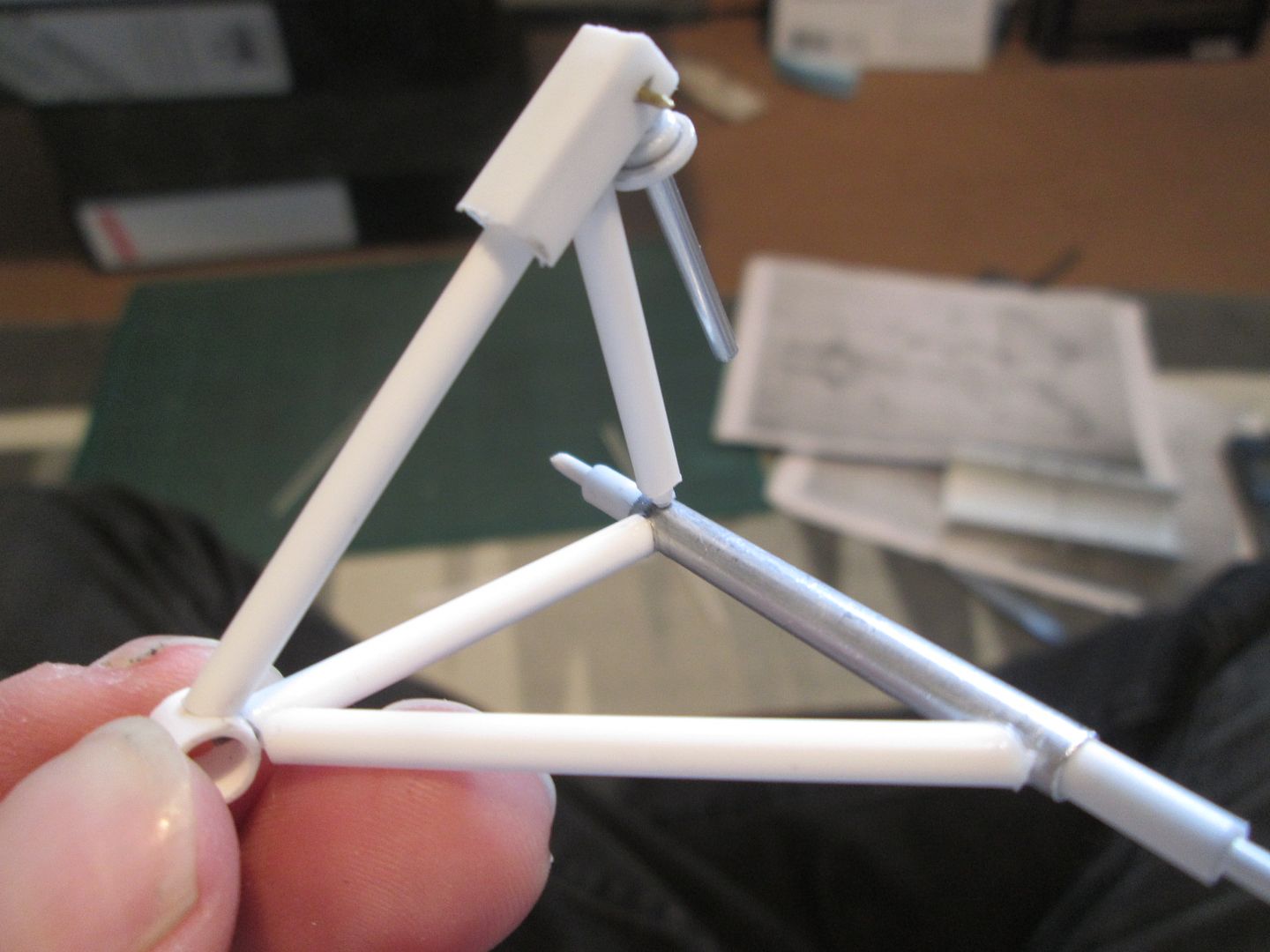 It's a mix of mainly 1/8" styrene and ali tube, with everything pinned together for strength. Later you'll see that I've added a closing plate to the damper support frame, plus there'll be another small frame on the inside to connect to the rear anti-roll bar, etc. Again, more work to do, but for now this is all I need to make progress. The rear uprights were a bigger challenge. Not necessarily a complicated shape, but complicated to work out how to make them accurately and strong enough as a fabrication, rather than as a casting. As usual, a piece of till-roll tube gave me the bearing housing section, and I added top and bottom extensions in styrene. The capscrew stub-axle was to be recessed into a series of plates which would form the front face of the upright: 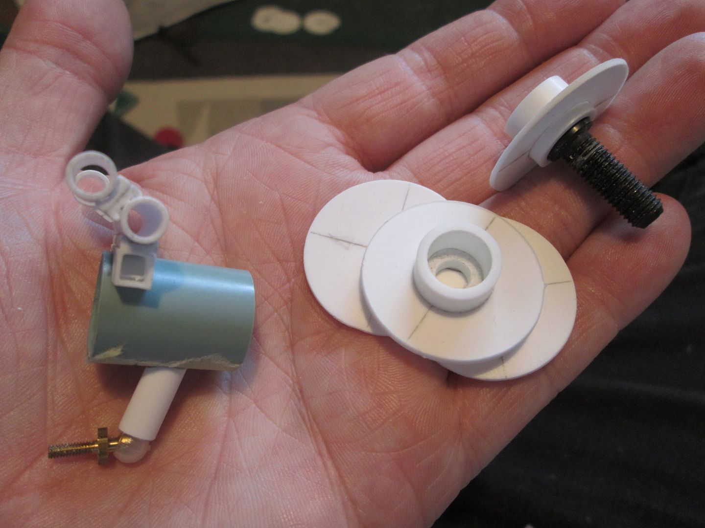 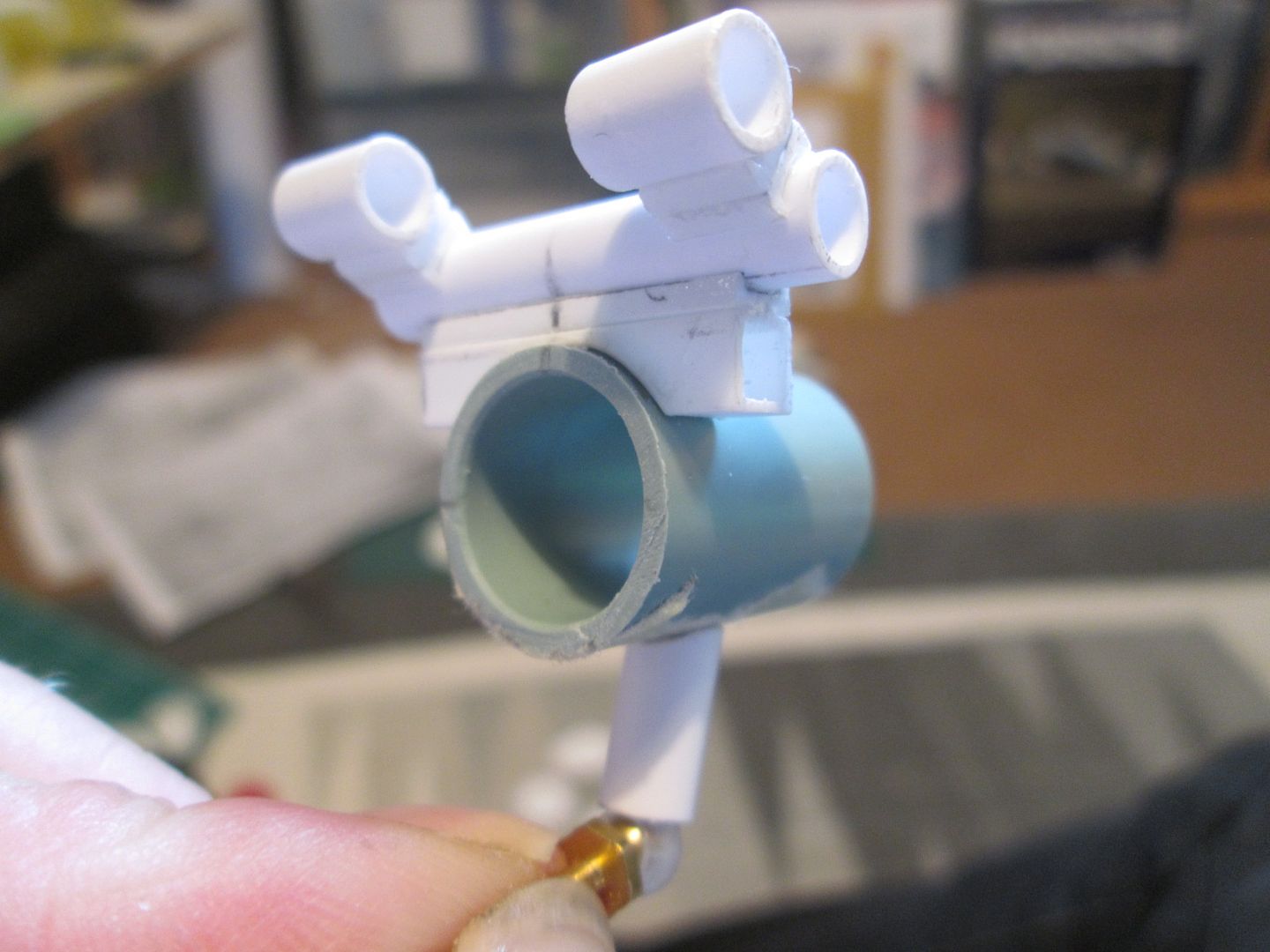 Then it was possible to start filling in the gaps around this core structure with more pieces of box-section, etc, and adding outer plates to create as much of the skin of the upright as possible. Four ali rods were drilled into the sides of each upright - these will be used to locate the brake calipers. You'll notice the way I fitted the RC car balljoints in the bottom - I usually incorporate the female section into the wishbone and the male part into the upright, but this time I've reversed them. I felt it would be easier this way - the lower wishbones are likely to be fairly 'lightweight' parts, and it would help if I didn't have to accommodate a relatively bulky socket piece into the design. I can still get enough angularity and movement, even though the joint is at right-angles to it's normal application. An extra bonus is that it'll be easier to adjust the final set-up of the suspension geometry by moving the male pin, rather than having to re-make the whole wishbone to move the socket. With a lot of greenstuff added to fill the gaps and smooth out the surfaces, I had these: 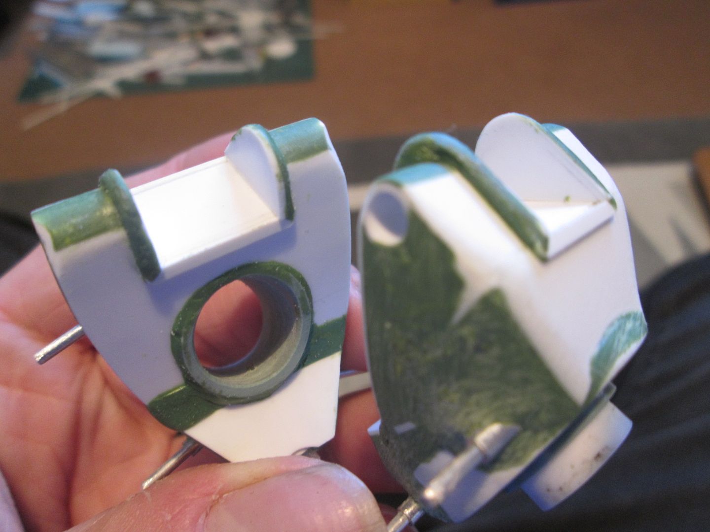 Not the best photo, but I think you get the idea! The final sequence of photos is what I've been working on for the last few weeks - gearbox bits. The front ends of the top wishbones locate into the 'ox-bow' across the back of the engine, but the rear ends are supported by a pair of fairly spindly-looking A-frames midway along the gearbox (which also extend beyond the wishbone to support the brake ducts). Problem one: how to make the frames strong enough. Problem two: how to control the accuracy of the two frames, and so the accuracy of the suspension. Problem three: how to mount everything to the gearbox so it doesn't fall off every five minutes. My solution to all three problems is below: 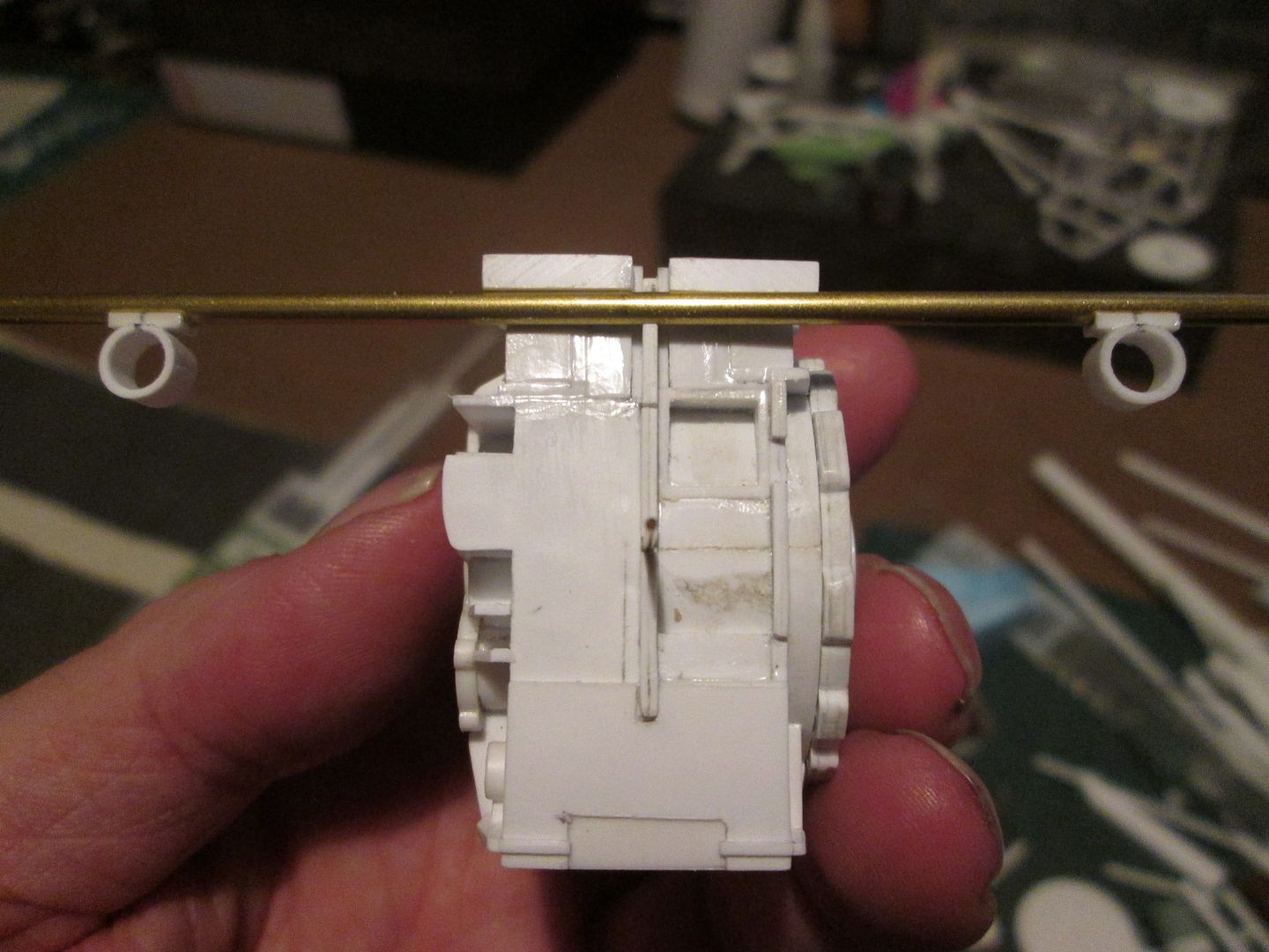 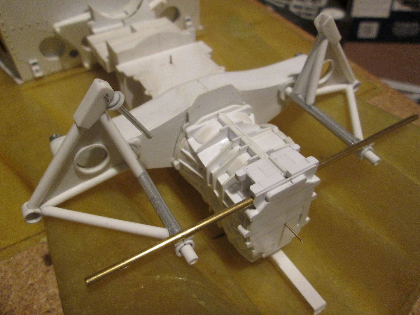 Instead of making two individual frames, I've made the main tube as a single length of brass rod, and will hang the pick-up bushes for the wishbone from this. A pair of stays will drop down to the lower part of the gearbox, either side. The top of the gearbox has been made so that the frame can either be lowered in from above, or slotted-in from behind. With the frame under control, I started making the end cover section: 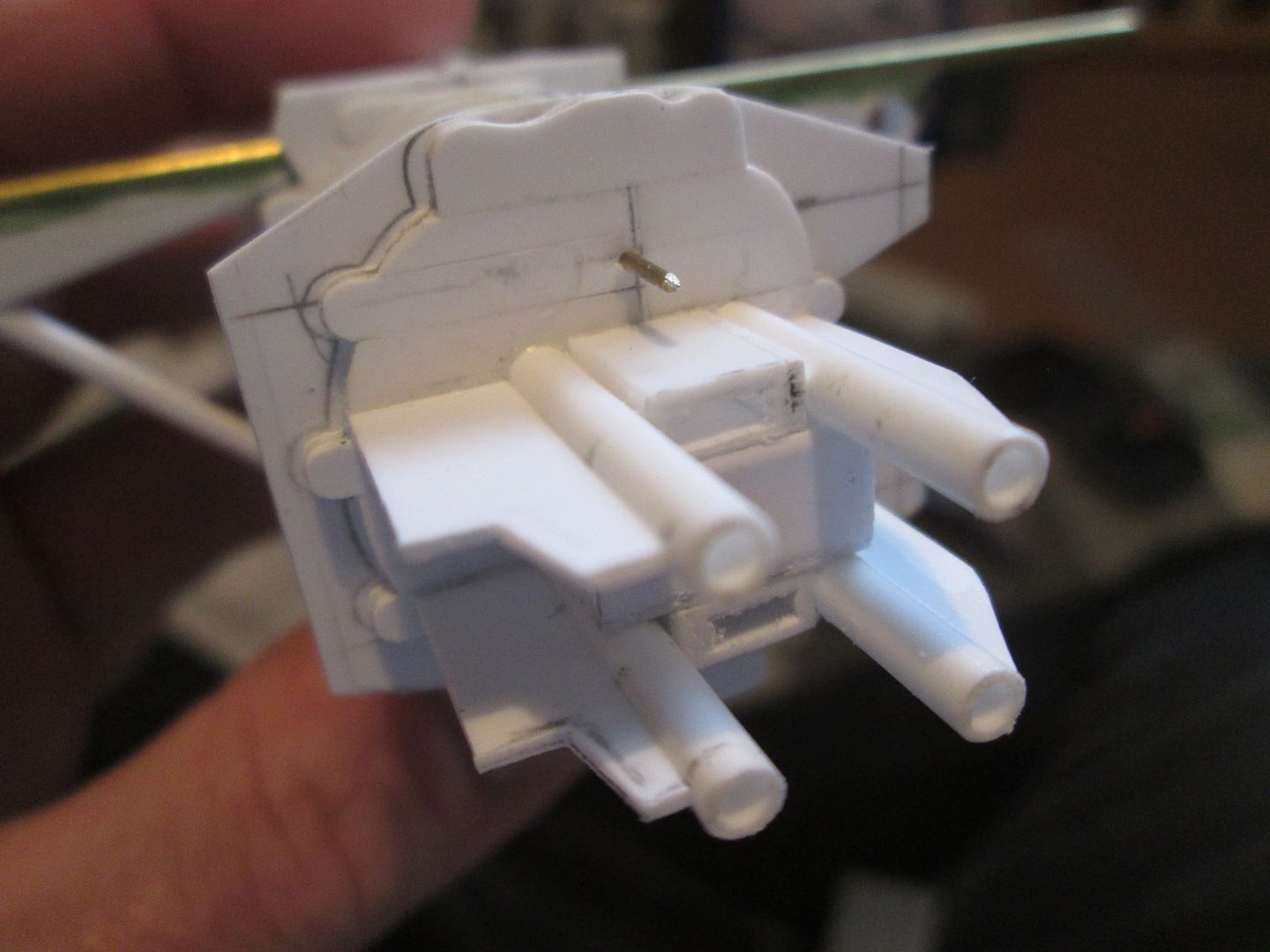 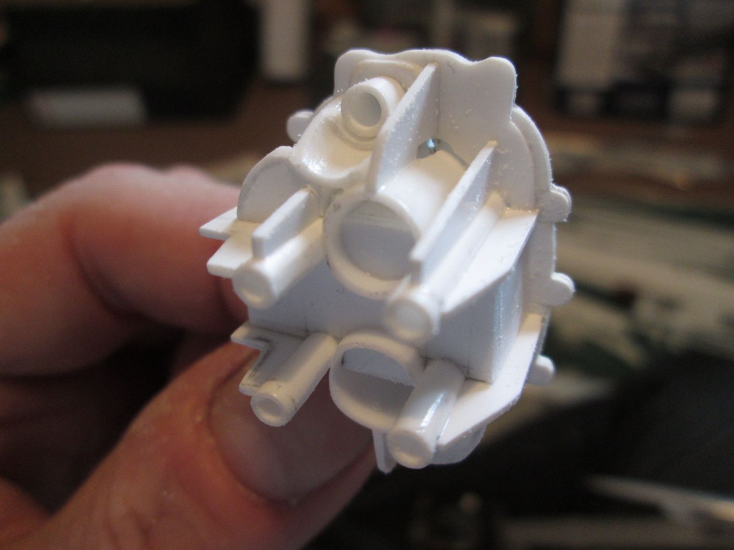 Again, it's a slightly odd shape to create, with the added complications of the various webs, curved sections, and the recess for the selector rod in the top. The four tubes in the middle are the mounting points for the rear air-jack - I've made these as a core part of the structure, just in case I decide to use the air jacks as a means of supporting the model at a later stage. After a week of working on the end cover, I've basically got a complete gearbox now: 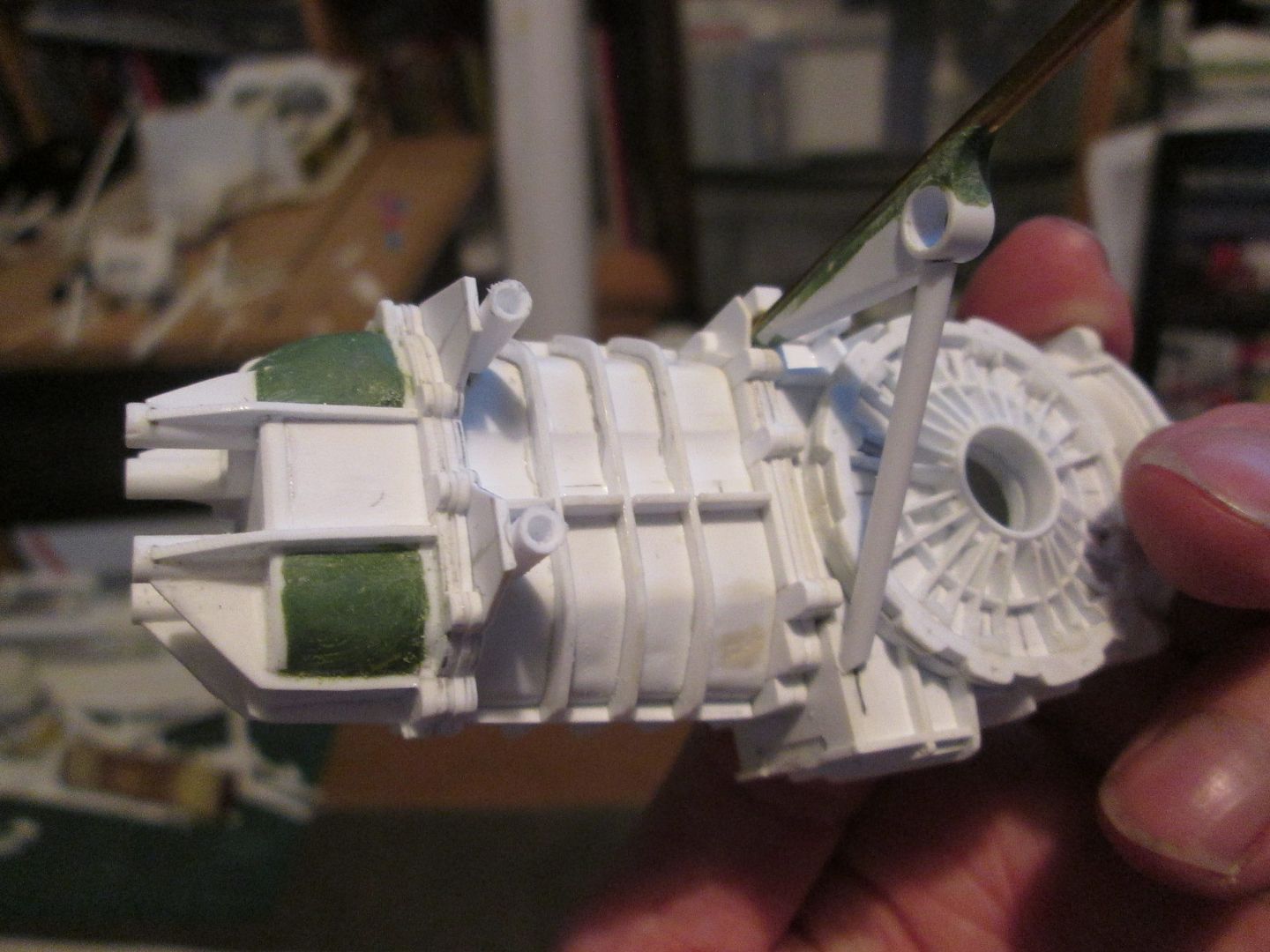 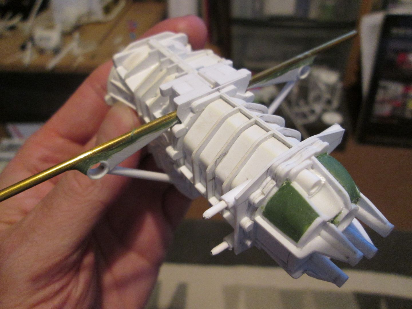 So, you can see that I've applied greenstuff to the end cover and to the wishbone support frame, plus I've made a start on the mounting points for the tail support frames. The lower legs of the wishbone frames are drilled and pinned and both ends - could give me problems when I do the final assembly, but I'll deal with that when it happens. There's more webbing and detailing to add on the gear-cluster section of the 'box, of course, and all sorts of other bits and pieces...but it's looking like a 956 gearbox! That's it for tonight - I'm officially now up-to-date! Have a good week, SB |
|
|
|
|
|
08-28-2020, 10:03 PM
|
#79 | |
|
Blarg! Wort Wort Wort!
Join Date: Mar 2006
Location: Quezon City
Posts: 2,120
Thanks: 64
Thanked 101 Times in 100 Posts
|
Re: 1/8 Porsche 956
another amazing update!
__________________
olly olly oxen free |
|
|
|
|
|
09-29-2020, 02:08 PM
|
#80 | |
|
AF Enthusiast
Thread starter
Join Date: Nov 2008
Location: Norwich
Posts: 649
Thanks: 21
Thanked 111 Times in 87 Posts
|
Re: 1/8 Porsche 956
Hello again!
I've spent the last few weeks continuing with work on the gearbox and associated parts. First up, I've added the horizontal web detailing on the gear cluster section of the 'box, various bosses and bushes, and the mounting tubes which will eventually support the tail brackets:  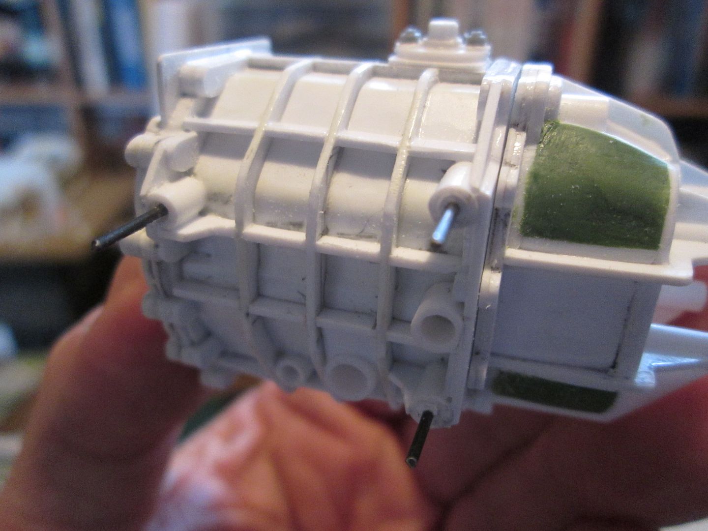 These two photos were taken a couple of weeks or so ago; in the last couple of days I've finished detailing the end cover with some oil feeds, extra webbing, hex nuts, etc: 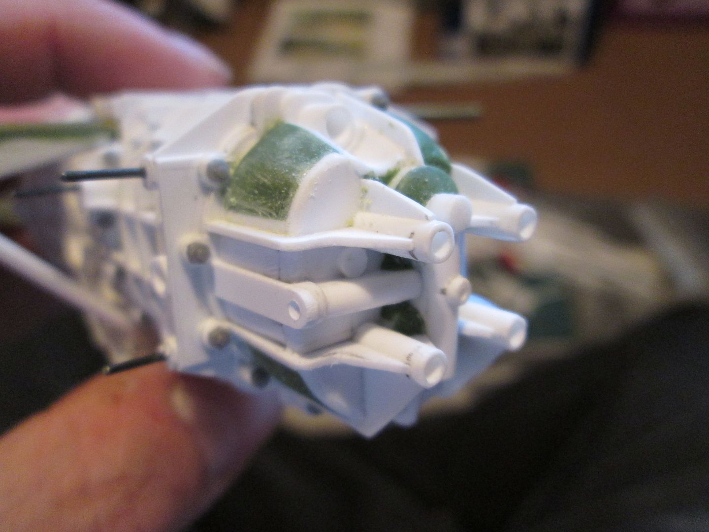 ...and a small oil pump down on the left-hand side: 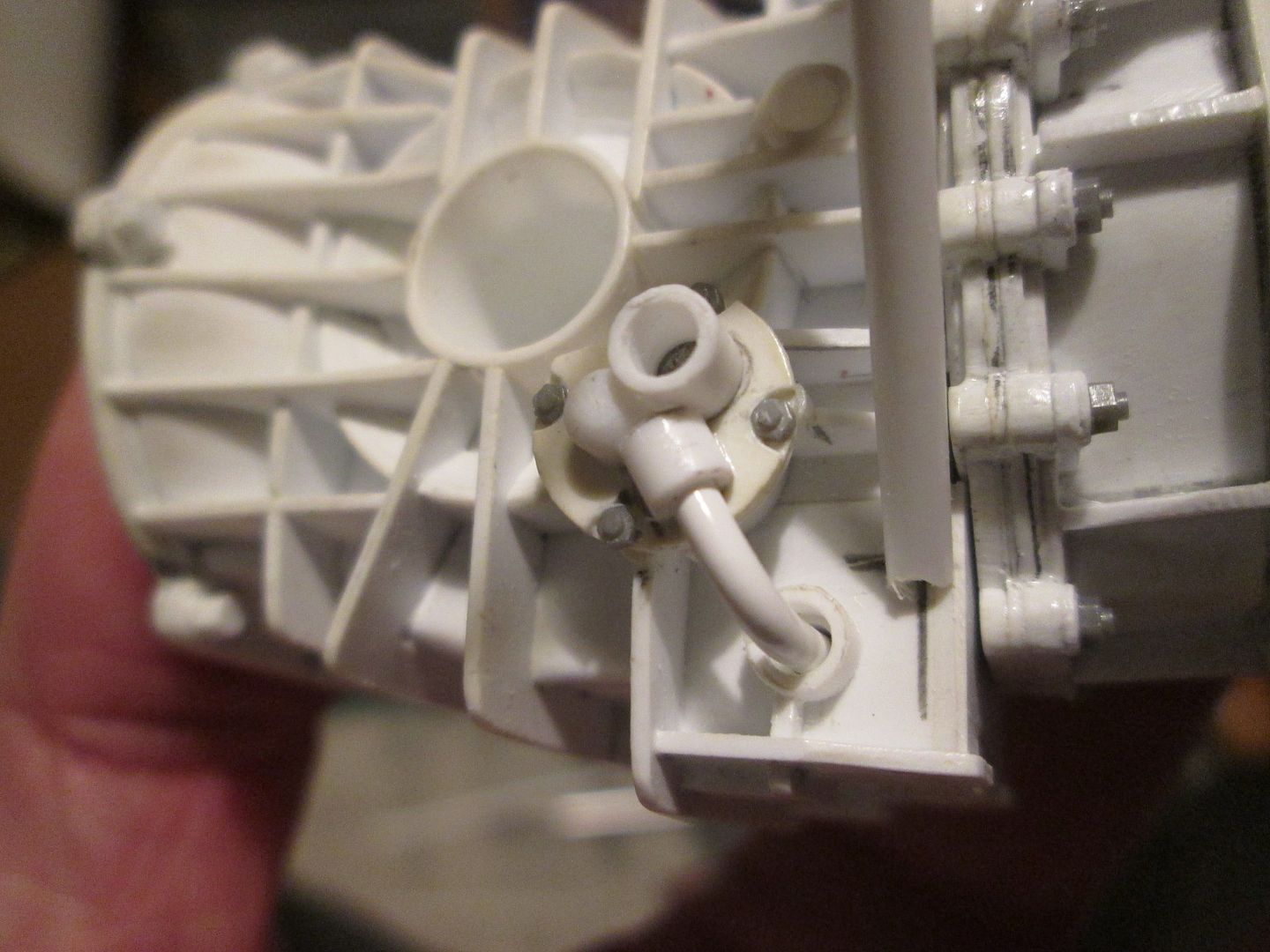 While in 'gearbox mode' I also made the rear anti-roll bar and mounting blocks: 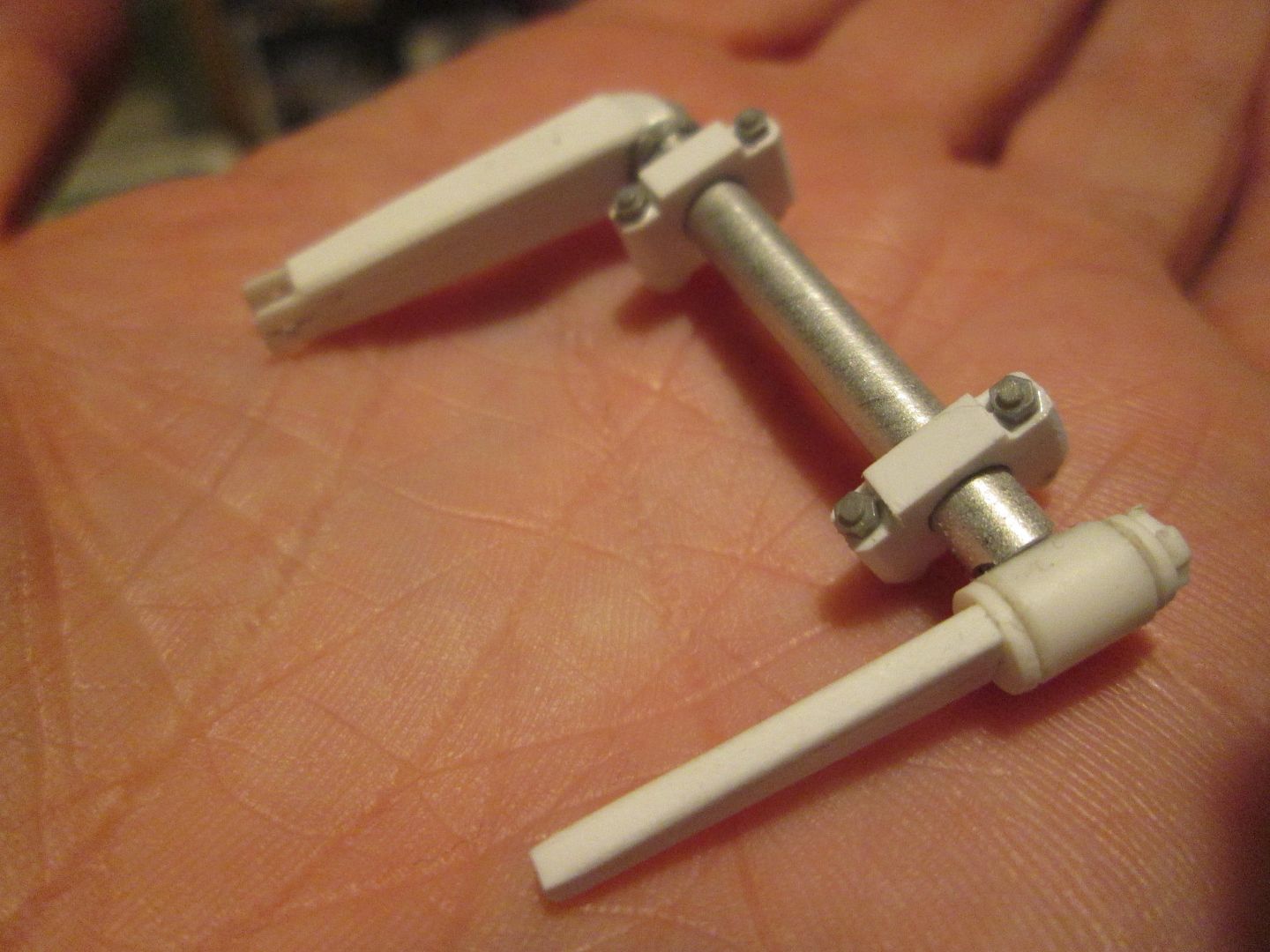 The aluminium crosstube section is in two pieces so the outer arms can rotate freely, rather than actually twisting the bar - what works in real life doesn't replicate in model scale. I've also made a start on the droplinks and the connecting arms which will be on the inner ends of the rear top wishbones, but these need more work when I've got the rear suspension in a more assembled state. Next, I returned to the 'ox-bow' adaptor between the engine and gearbox. This has an upper cover section which allows access to the clutch mechanism and mounts the slave cylinder, ignition coil, etc. I made the baseplate for this early last year while making the rest of the ox-bow, but didn't need to do anything with it for a while...until now. Here's the plate, with some of the other component parts in the early stages: 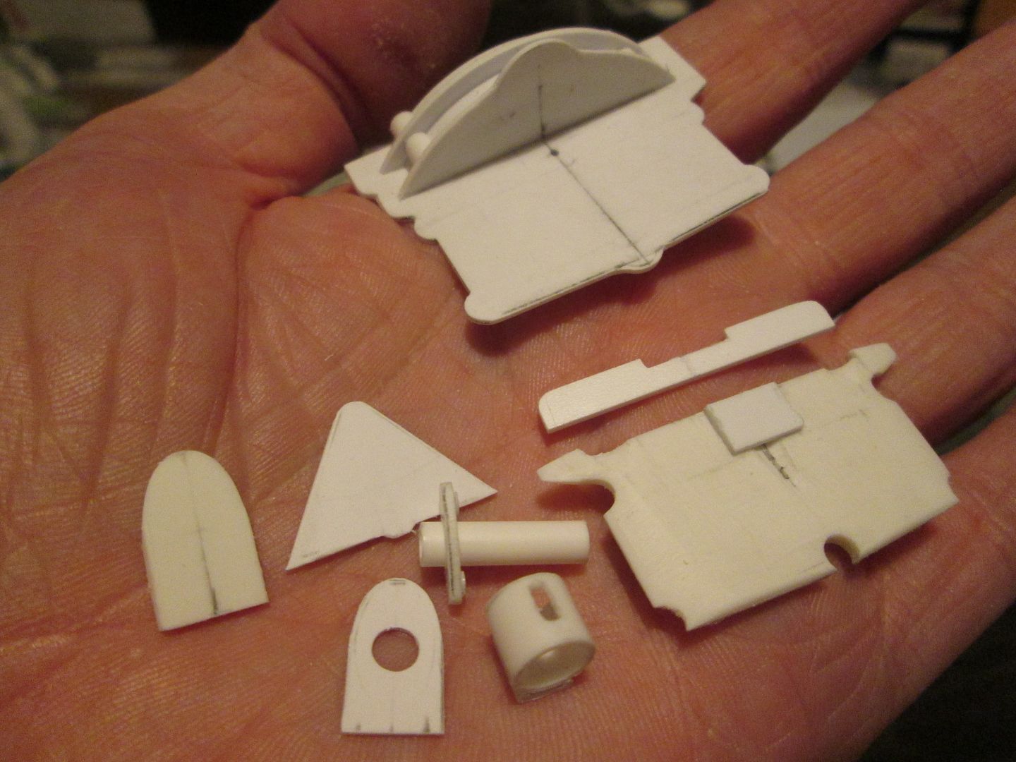 ...and after more work: 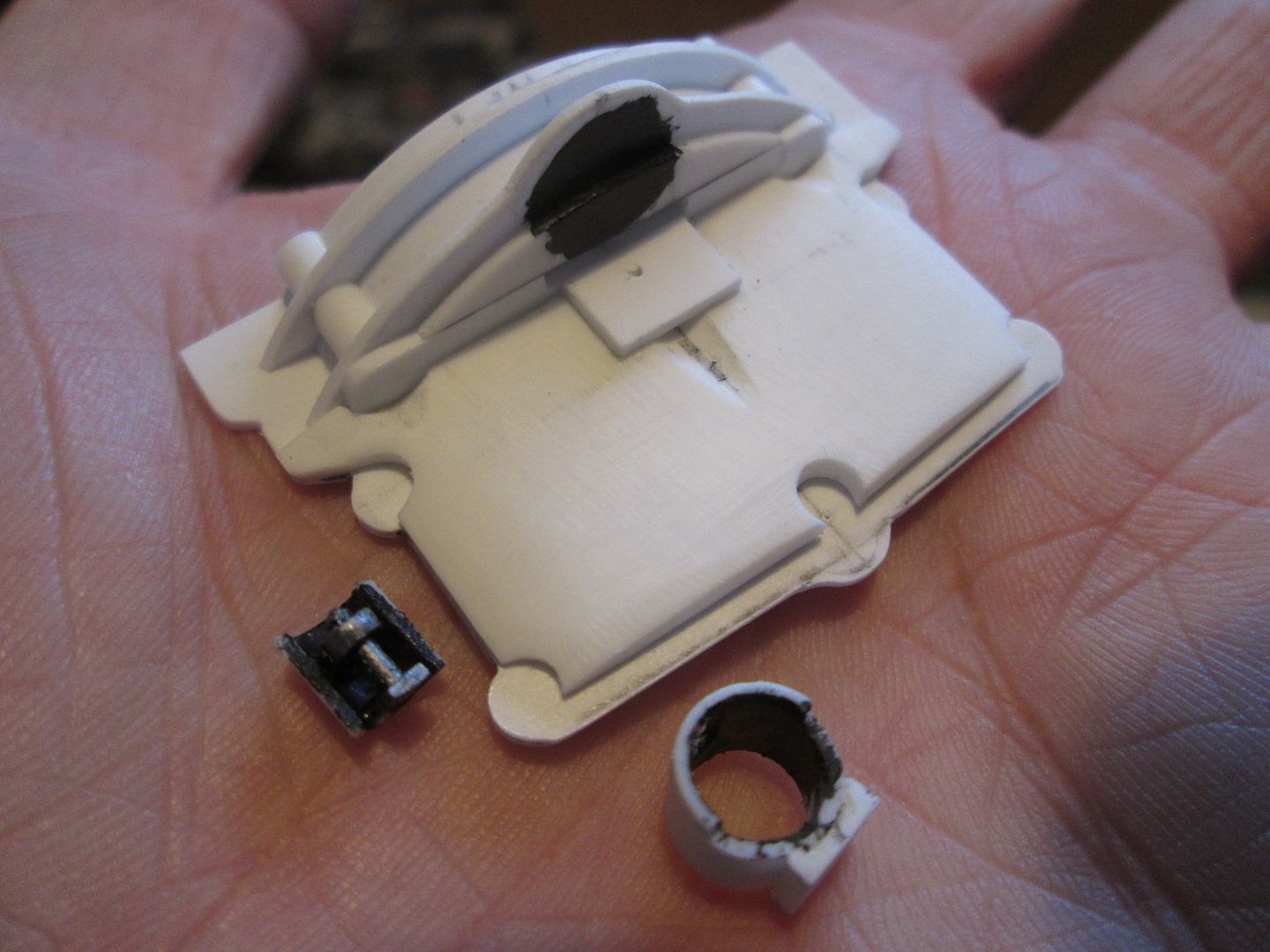 ...and with some more detailing: 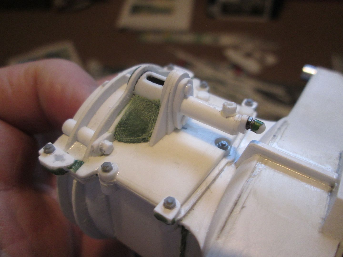 The little piece of painted mechanism you can see in the second photo is fitted inside the tube ahead of the slave cylinder, and is visible through the slot in the top. Another one of those little things that doesn't really need to be there and will only be seen properly by a handful of people! The slave cylinder was one of a few small parts made in the last couple of weeks: 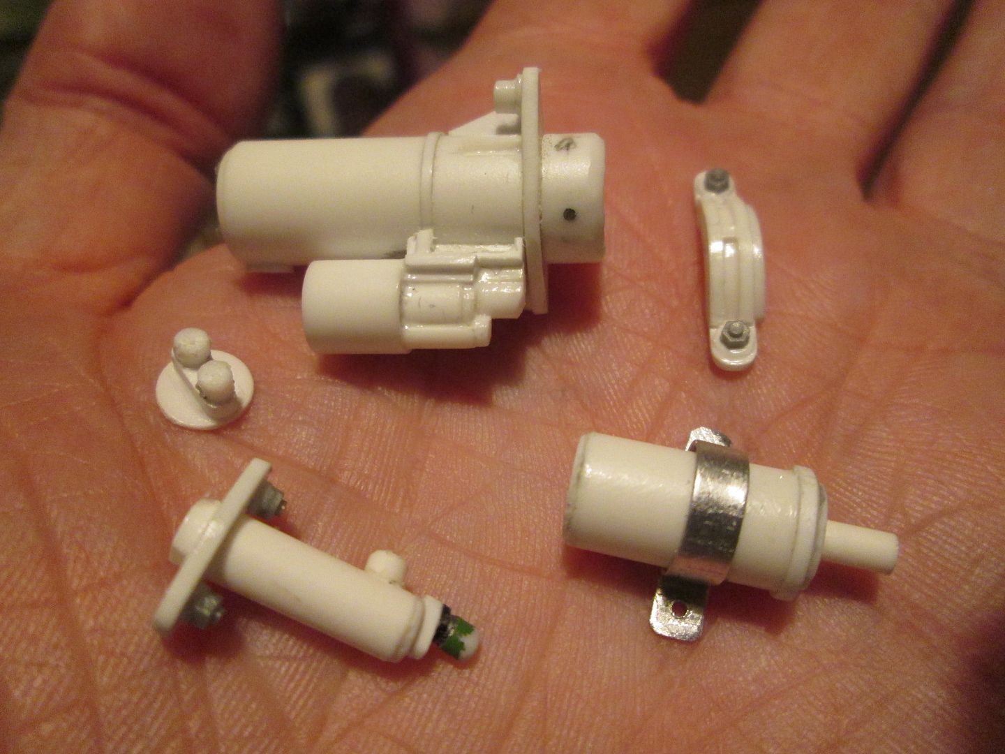 From the top moving clockwise: starter motor, starter motor 'bridge', ignition coil, clutch slave cylinder, starter solenoid end cap. The coil mounting varies from car to car - on some it attaches to a plate and then to the top of the ox-bow cover, on other cars it bolts straight onto the cover; I'll worry about this later. The starter motor was one of those satisfying weekend jobs - begin on Friday night with a collection of bits of tube and some photos, and by Sunday night it's pretty much ready to paint. Lots of small bits of strip and detailing where the solenoid connects to the main body, provision for the wiring to connect, etc, and a secure pinned connection into the side of the ox-bow. The 'bridge' piece fits onto the side and covers where the starter pinion would be, reinforcing the ox-bow casting: 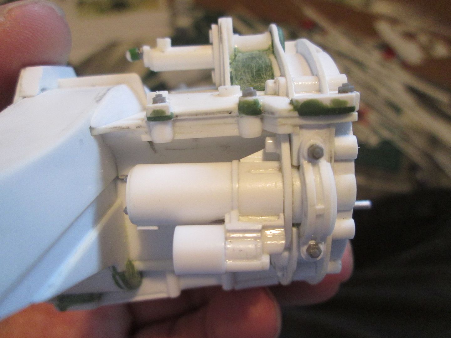 What next? I'm getting to the stage where I feel like a change from making gearbox parts - seems like that's all I've been doing all summer! I guess I can either go back into the cockpit - fuel pumps, fire extinguisher pipework, seat and seatbelts, etc - or make a start on the eight brake calipers, so I can then think about making some wheels. Or I give the radiators and intercoolers some serious thought - I really want to improve on how I make the fins on these, but I'm struggling to work out how I can do it (relatively) easily...and without losing my mind. If anyone out there can do custom photo-etch to spec, I might be interested in having a chat! All the best, SB |
|
|
|
|
|
09-30-2020, 07:48 AM
|
#81 | |
|
AF Enthusiast
Join Date: Jun 2006
Location: west bend, Wisconsin
Posts: 580
Thanks: 12
Thanked 72 Times in 67 Posts
|
Re: 1/8 Porsche 956
Always amazed at the craftsmanship and detail you put in! Stunning work so far!
Mike |
|
|
|
|
|
09-30-2020, 08:20 PM
|
#82 | |
|
AF Regular
Join Date: Mar 2005
Location: San Marcos, California
Posts: 331
Thanks: 52
Thanked 17 Times in 15 Posts
|
Re: 1/8 Porsche 956
Scratch Building at its finest.
|
|
|
|
|
|
10-19-2020, 02:17 PM
|
#83 | |
|
AF Enthusiast
Thread starter
Join Date: Nov 2008
Location: Norwich
Posts: 649
Thanks: 21
Thanked 111 Times in 87 Posts
|
Re: 1/8 Porsche 956
Cheers, guys!
Okay - time for a change of scene. Since the last update I've been working on the brake calipers - never my most favourite job but (A) I can't avoid them forever and (B) once they're done I can start thinking about making some wheels! Why am I not keen on them? They're always a complicated shape which doesn't immediately lend itself to construction using box-section or tube. They have to be accurate - you're trying to wrap them around the disc while keeping within the confines of the wheel. They require fiddly details like the pad retaining pins and the brake-line fittings. And in the case of the 956, you have to make eight of them, not just the normal four! So, the first step was to work from the drawings and mark out the basic measurements on 0.75mm styrene: 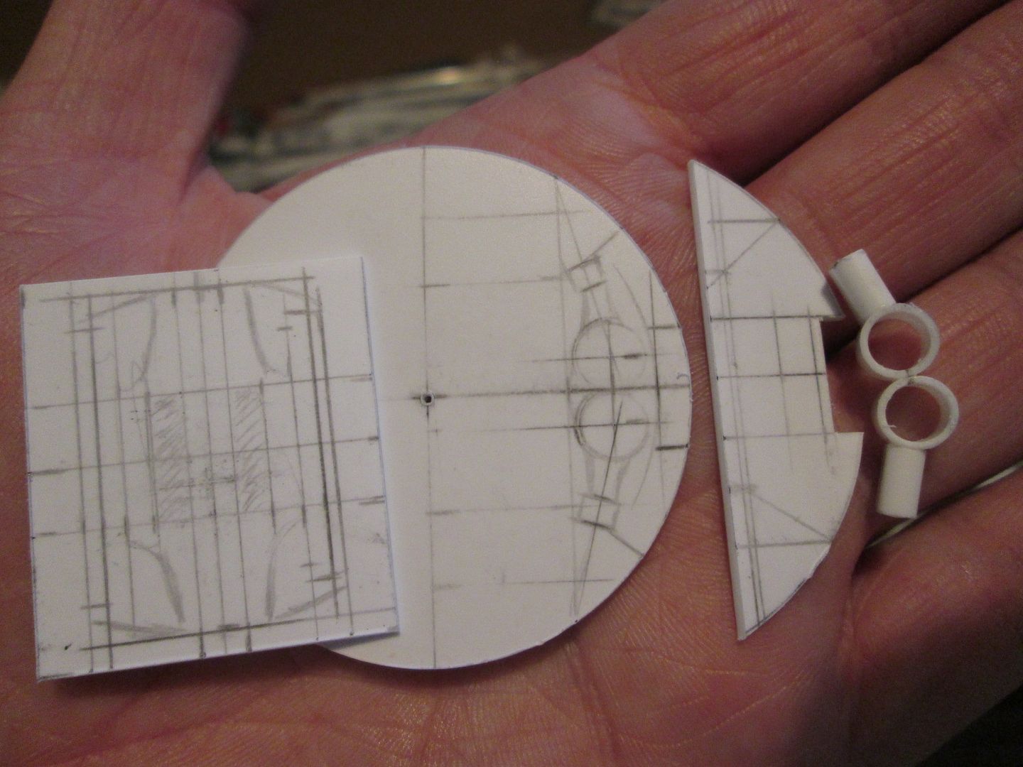 They're a four-piston design, but my first reaction once I'd drawn them up was that - compared to the 935's calipers - they seem really small! My plan was to make each caliper from two main side plates, space these either side of the disc using sections cut from suitable 8mm box, then layer on the detail. As with the 935 I'll have the pads as separate slide-in parts. I spent most of a weekend fiddling around until I came up with this: 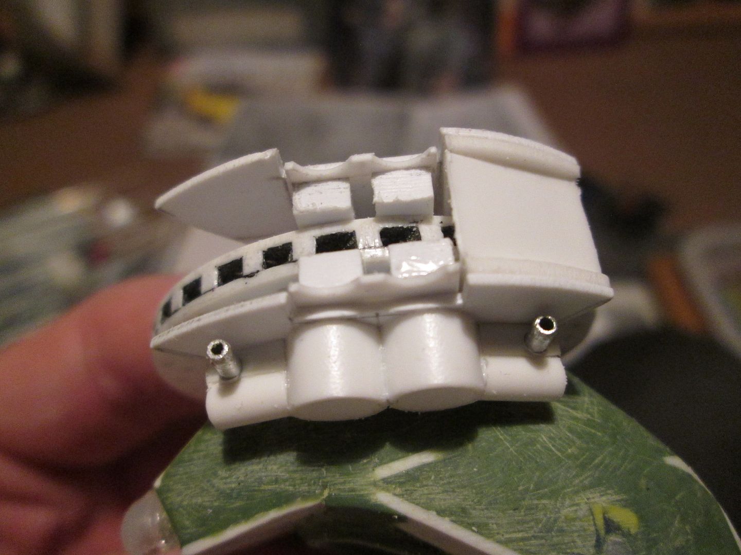 This prototype proved the concept would work - now to put it into production! I wanted to make the main parts with a minimum of measuring, which would hopefully keep the accuracy high, and also save a lot of time. Economy of effort, I think. I couldn't face the idea of making all eight calipers on one go, so I started by marking out the plates for the first four: 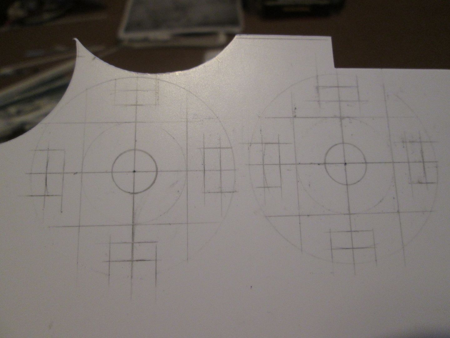 Laying them out like this meant a major reduction in time spent measuring and marking-out - I could just transfer everything from one side to the other. I could cut out the two discs with the compass-cutter, rather than trimming out each section separately then having to spend time filing and smoothing. The notch where the pads slide in could be fixed and cut accurately at this stage, and would then be the reference point for fitting the two tube sections for the pistons. 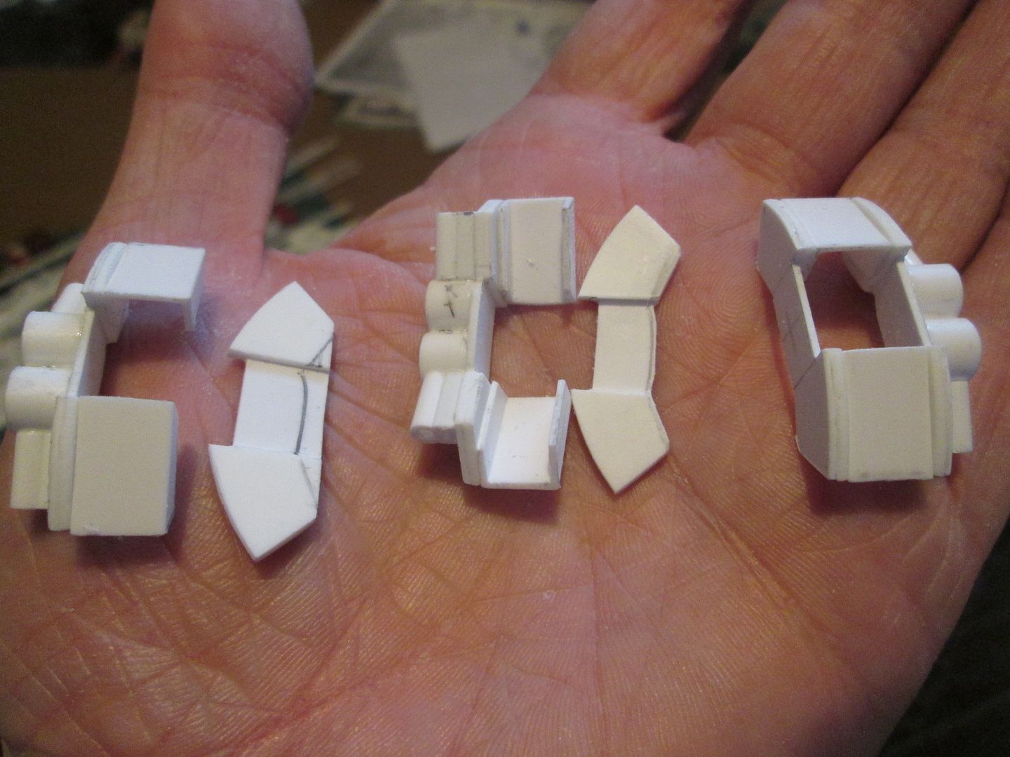 I've tried to build them in such a way that after the initial marking-up, each stage adds new components using the caliper itself as the template, rather than having to measure and mark new points. For example, after cutting the main side plates I needed to add a pair of 1mm spacers to the inside - rather than marking and cutting these extra plates separately to exact size, I made them as simple squares, glued them in place, then cut and filed them back to shape using the main plate as the guide. After a week's work, I had four basic caliper cores: 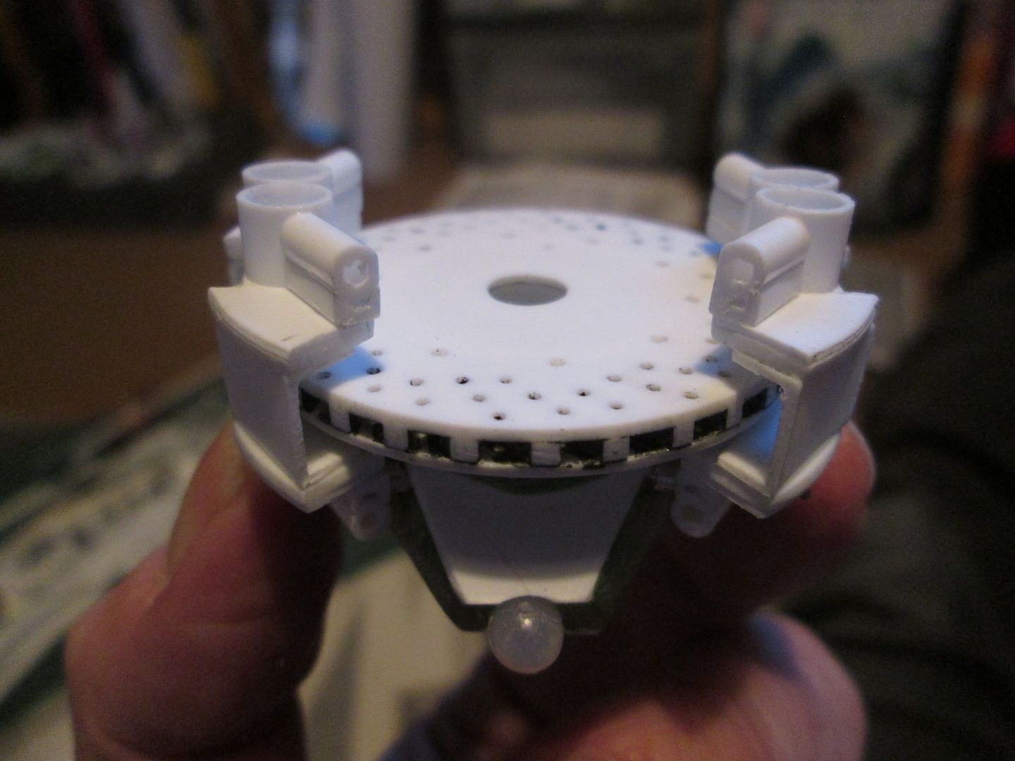 ...and I should still be able to fit everything inside the wheel-rim: 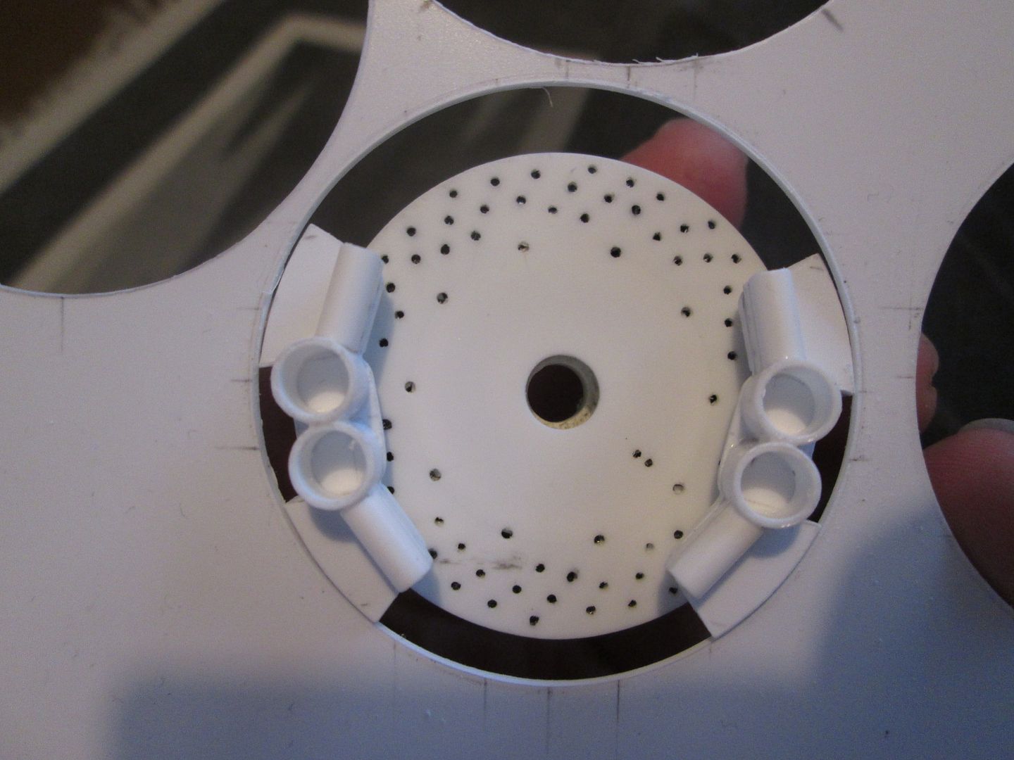 So after a week or so working on the first four, I spent this last weekend making the next four: 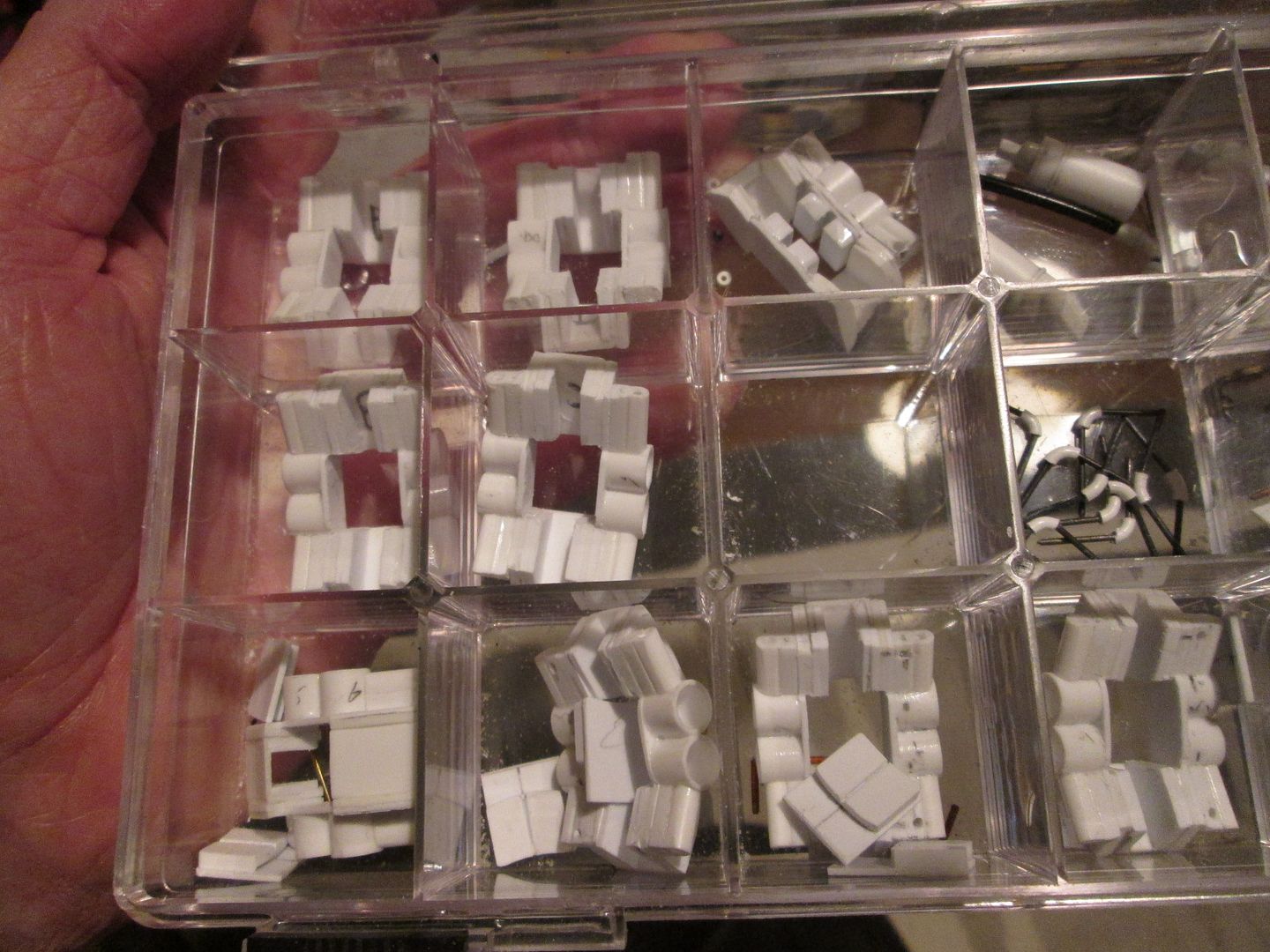 The original four are on the bottom row, the second four are at the top. You can just see that I've started making the brake pads too, and have added strip and plate to the internal surfaces of all eight calipers to bulk them out around the disc. There's still more work to be done - I'll probably be on these all month - but I now feel that the hard work is behind me. I'll spend the rest of this week getting all eight to the same stage: drilled to suit the mounting lugs on the four uprights, extra strip on the inside, pads made. Then I'll start on the fine detailing around the outside, adding greenstuff to smooth out the shape, etc. Have a good week, SB |
|
|
|
|
|
10-20-2020, 04:44 AM
|
#84 | |
|
Blarg! Wort Wort Wort!
Join Date: Mar 2006
Location: Quezon City
Posts: 2,120
Thanks: 64
Thanked 101 Times in 100 Posts
|
Re: 1/8 Porsche 956
question - assuming you have identical parts, would it be quicker to do all one-by-one, or finish one, and then just make a mold and make casts for the rest? i'm thinking the former is cost-effective, but the latter might (?) be quicker
__________________
olly olly oxen free |
|
|
|
|
|
10-20-2020, 01:33 PM
|
#85 | |
|
AF Enthusiast
Thread starter
Join Date: Nov 2008
Location: Norwich
Posts: 649
Thanks: 21
Thanked 111 Times in 87 Posts
|
Re: 1/8 Porsche 956
Good point. When I see some of the great components and bodyshells that people have resin-cast on this forum, I often think that it's something I should try myself sometime - but I never get around to it! It's an investment in time, materials and a new learning process, and I guess it's always just easier for me to start cutting styrene instead. Once I've started making the calipers it's not so bad - it's more the thought of making them that I don't enjoy!
Maybe on the next project... SB |
|
|
|
|
| The Following 2 Users Say Thank You to ScratchBuilt For This Useful Post: |
nugundam93 (12-05-2020)
|
|
11-30-2020, 02:24 PM
|
#86 | |
|
AF Enthusiast
Thread starter
Join Date: Nov 2008
Location: Norwich
Posts: 649
Thanks: 21
Thanked 111 Times in 87 Posts
|
Re: 1/8 Porsche 956
Hello folks,
Hard to believe, but I'm nearly two years into this project now. I'll do some 'kit shot' photos at the end of the year showing everything I've made so far, but I do feel like I'm making good progress. Of course, I've still got a lot of fibreglassing to do, wiring and plumbing, half an engine to build, etc, so it won't be finished any time soon! First up tonight, the next stage in making the brake calipers was to add some small lengths of angle section to define some of the shape that would be added afterwards with greenstuff: 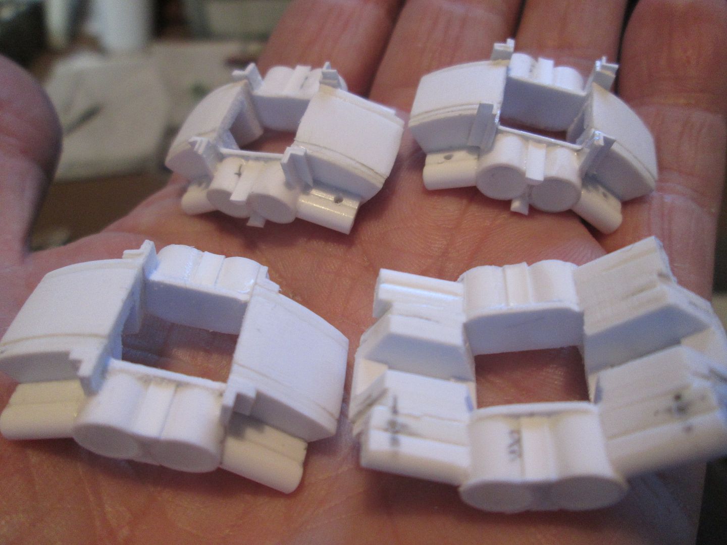 ...and then to add and smooth the greenstuff: 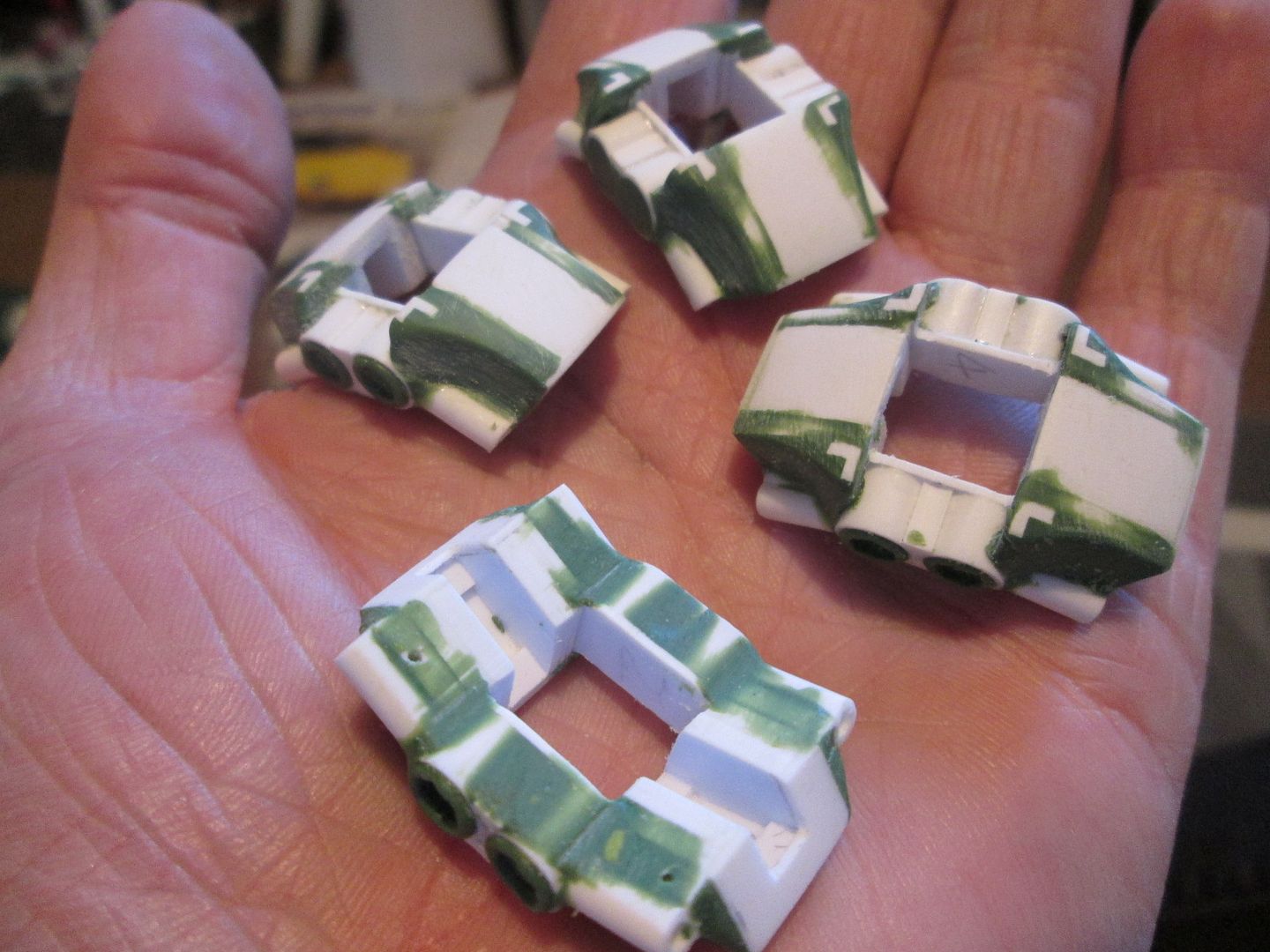 Still more to do, but by this stage I felt like a change of scene was required. So, time to make a start on the wheels. The basic construction would be as per the 935 - make inner and outer rim sections by layering thin styrene sheet, add a centre hub, then assemble the whole lot into a blue foam tyre. Although wheel sizes varied as the 956 developed in to the 962, I've gone for the early 12" x 16" fronts and 15" x 16" rears. After taking measurements from the drawings, and checking with the hub and upright parts I'd already made, I could start cutting lengths of 0.4mm styrene sheet and coiling it into the same foam block I used for the 935: 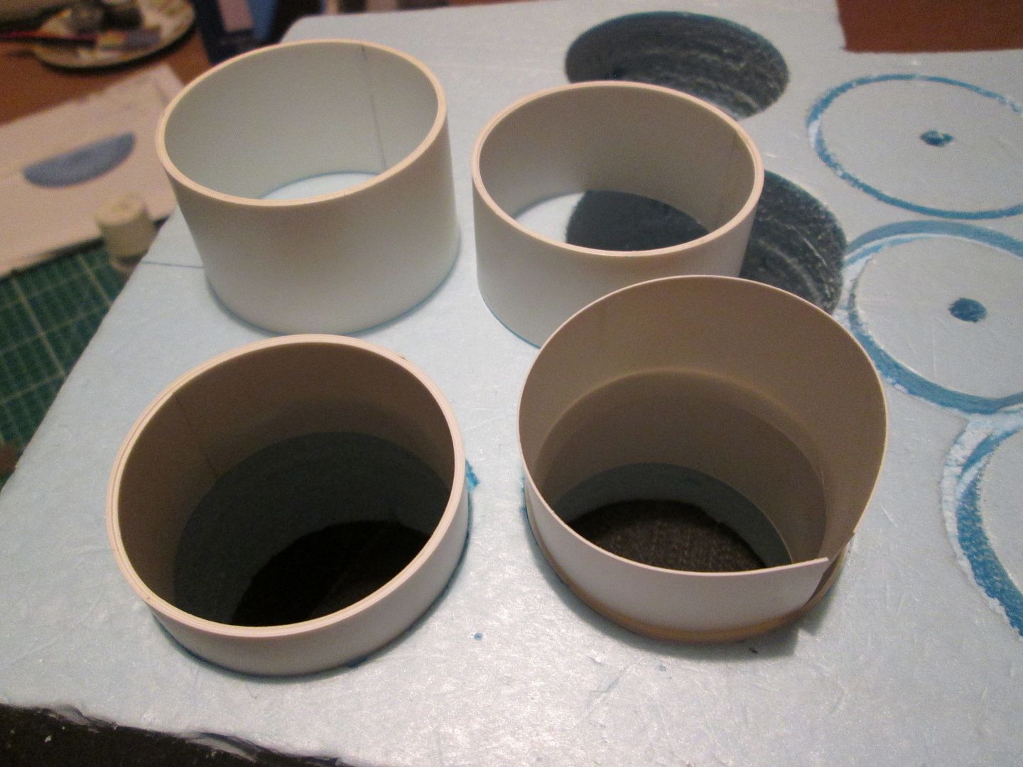 These are the four inner rims, each one made from four layers. The thinner outer rims were made in exactly the same way. For the wheel centres, I've used a six-spoke design to match the original factory-fit Speedline wheels - it's quite possible they will eventually have some sort of fibreglass aero covers fitted, but for now the spokes will be visible. My plan was to sandwich a layer of 1/8" box section and strip between two 0.75mm outer skins. The six spokes would complicate matters, but by making a styrene template which could be repeated for all eight outer skins, I would cut down the amount of time measuring and marking out - and improve the accuracy: 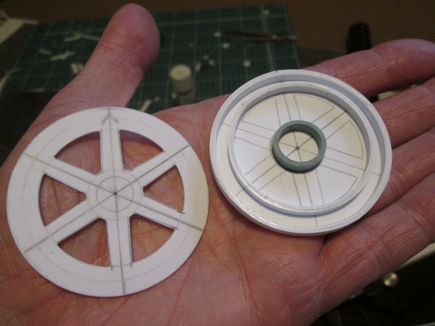 More 1/8" strip was coiled up in layers to make the inner and outer edges, and a length of my trusty credit-card terminal till-roll tube used for the centre. Lengths of 1/8" box were added to create the cores of the spokes, then some 1/8" x 1.5mm strip to form the sides (with spacers at the inner end to set the appropriate taper. The centres were sleeved down using more styrene tube, and will need one more 'layer' to reduce to the correct size for the stub-axles - this final piece of tube will also be used to get the overall offset of the wheel correct: 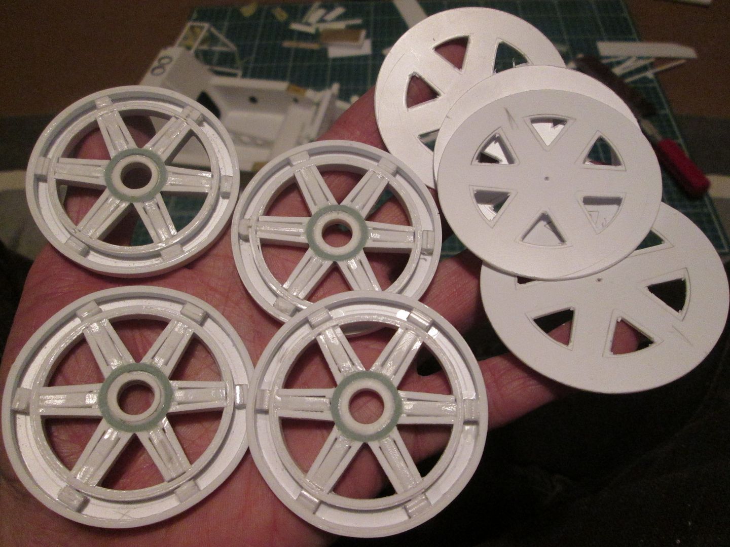 You'll see how these worked out next time. While all this was going on, I was also working on the next job - radiator cores! A few posts ago I mentioned that I was considering using photoetch to create the fine pattern of tube-and-fin detailing required for the various rads and coolers. I've used various methods in the past, but always felt that it could be improved; however, it's such a fine 'texture' that I haven't been able to come up with anything that works...until now. I did some searching online, and found the website for '4D Modelshop' in London. Lots of useful info, guidelines and suggestions, and price information. From all this, and a few emails exchanged with Iain, I was able to send them a drawing of what I wanted, and barely a couple of weeks later I had an A5 sheet of 0.2mm thick brass photoetch rad mesh! I resisted the temptation to get on with the rads immediately (wanting to get the wheel components to a suitable state first), but last weekend I made a start. It's early stages, but here's the first of the main water rads: 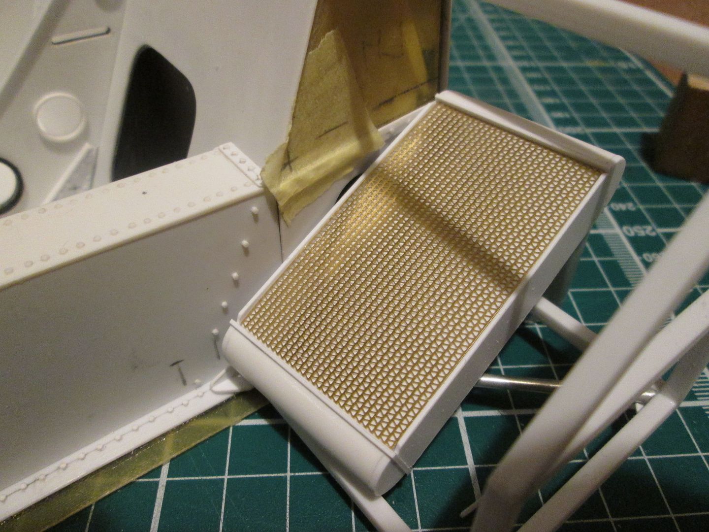 The tubes are 0.4mm wide, with a 0.75mm section of 0.25mm fins between. I've adjusted the measurements a little from 100% scale-accurate to suit the requirements of the photoetch process, and to make the angled fins more noticeable, but it doesn't hurt - I think it looks great! Of course, I now have to work out how to paint it without obscuring all the detail, but that's a problem for later. Much better than spending hours gluing on dozens of lengths of 0.5mm styrene strip, and also better than just using regular 'square' mesh. It wasn't cheap (look at the website!) but my view is that on a project like this, the costs are spread over several years - and in the two years so far all it's really cost me is styrene, some fibreglass, glue and greenstuff, and lots of hours of my time. I reckon I have enough of the photoetch to do a second project, but can get another sheet made if required. I'm now working on the oil cooler and intercooler cores for the left-hand side, but won't cut the photoetch for these until I'm sure all the sizes are correct, and that nothing needs adjusting. So far, so good! SB |
|
|
|
|
|
12-05-2020, 01:44 PM
|
#87 | |
|
Blarg! Wort Wort Wort!
Join Date: Mar 2006
Location: Quezon City
Posts: 2,120
Thanks: 64
Thanked 101 Times in 100 Posts
|
Re: 1/8 Porsche 956
wow. another awesome update!
__________________
olly olly oxen free |
|
|
|
|
|
12-10-2020, 02:29 PM
|
#88 | |
|
ItaloSvensk

Join Date: Mar 2009
Location: Marstrand
Posts: 3,383
Thanks: 1,077
Thanked 296 Times in 270 Posts
|
Re: 1/8 Porsche 956
Always fantastic job
__________________
Paolo - LoveGT40 Modelworks website www.alsoldatino.com my YT channel : https://www.youtube.com/channel/UCIp..._as=subscriber FB: https://www.facebook.com/alsoldatino |
|
|
|
|
|
12-10-2020, 04:49 PM
|
#89 | |
|
AF Enthusiast
Join Date: Sep 2011
Location: Redwood City, California
Posts: 651
Thanks: 0
Thanked 39 Times in 39 Posts
|
Re: 1/8 Porsche 956
Mind blowing...
|
|
|
|
|
|
12-31-2020, 07:13 AM
|
#90 | |
|
AF Enthusiast
Thread starter
Join Date: Nov 2008
Location: Norwich
Posts: 649
Thanks: 21
Thanked 111 Times in 87 Posts
|
Re: 1/8 Porsche 956
Hello again!
As usual, I like to try to tidy up all the loose ends at the end of the year - mainly to remind me of what progress I've made, but also to prove that my lack or regular updates is not necessarily due to having nothing to show! Other than a couple of days either side of Christmas there's been very few days when I haven't done any modelling - I didn't have the enforced break for Le Mans weekend either! Like many others, I would have preferred to have been in France, though... So, back to the end of November. Before cutting any more of the photoetch mesh I wanted to make the basics of the two oil coolers and intercoolers, to confirm that everything would fit together. The oil coolers were just a smaller version of the two main water rads already shown, but the intercoolers are a little more complicated. At this stage all I needed to make was the main body of the air-to-air core, and the outer end tank / air-to-water core: .JPG?width=1920&height=1080&fit=bounds) Nothing too unusual. I wanted to get a nice smooth outer edge for the air/water core section so used the 1/8 box and tube elements to define the perimeter before wrapping thin strip around the outside. The main intercooler core section was skinned with styrene, with some crafty detailing added to trap the photoetch in place later - you'll see this in more detail when I show the finished parts in 2021! The next photo shows all three coolers mounted on the left-hand side of the tub: .JPG?width=1920&height=1080&fit=bounds) .JPG?width=1920&height=1080&fit=bounds) The oil cooler hangs from the top of the sideframe with a couple of pins and a small plate, with an extra tube added to the frame to hold the lower tank in place. The intercooler has a bracket on top which hooks over the frame - this will all be hidden once the bodywork is added. The weight causes it to droop a little right now, but the pipework connections to the turbos and other coolers will all help to lock it into place. Having spent most of early December working on the coolers, I wanted to do something different during the Christmas break - turbos! As these were effectively a repeat of what I'd done for the 935 I dug out my old notes and photos, compared these with my reference drawings for the 956, and satisfied myself that they were the same units on both cars. I kicked myself for not making more notes, though, as it was surprising how few measurements I had of what I'd actually made! I'll make sure I don't make the same mistake twice, as there's bound to be another 1/8 Porsche in build in a few years... Here's the cores of the four units: .JPG?width=1920&height=1080&fit=bounds) ...and after plenty of Greenstuff and more detailing: .JPG?width=1920&height=1080&fit=bounds) Still lots more to do, but this is how I need them for now while I'm working on positioning, mounting, etc. Yesterday I was working on the two inlet trumpets: .JPG?width=1920&height=1080&fit=bounds) I'm pleased with the end-pieces with the mesh coverings (start as a 20mm mesh disc, formed over progressively smaller diameters of tube), but the main trumpet needs some subtle shaping to create more of a tapered profile. Annoyingly, these parts are not shown on any of the reference drawings I'm working with, and tend not to be visible in 99% of the engine-bay photos. I'll finish these as a Mk1 version, but I'm not ruling out a Mk2 version if they don't look 'right'. The back end of the turbo units hangs on a mounting plate attached to the rear of the sideframe. I'd not added these extensions until now, as they would have been vulnerable, but - needs must: .JPG?width=1920&height=1080&fit=bounds) The main problem with these was that I couldn't drill and pin them to the main sideframe as much as I would have like - the pins holding the sideframe in place are already in the way! The pins you can see will help, but I've also added some strategic fibreglass gussets in a couple of places. Later I might even consider adding a thin outer skin to these sideframes, as it'll be hidden once the main bodywork is fitted. With these extension frames fitted to both sides, I could start dummying-up the turbo positions relative to the intercoolers: .JPG?width=1920&height=1080&fit=bounds) The pipework between the turbo and the intercooler will be used as a structural support, so I'll be juggling these bits around for a while yet. The trumpet will extend forwards alongside the main water rad and receive air from the door duct. There'll be more pipework for the water feed back to the engine, plus the exhaust pipes coming out to drive the turbos. That's pretty much where I'm up to now after two years working on the 956. Here's what I'd done by the end of 2019: 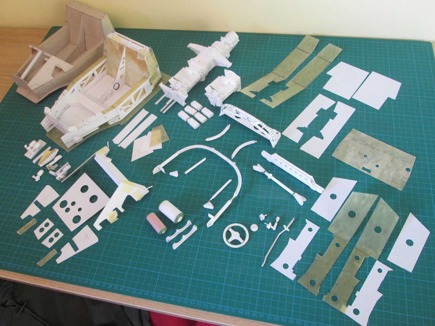 And by this morning: .JPG?width=1920&height=1080&fit=bounds) I'd say that was good progress for the year! As always, thanks to everyone who has been following this thread, thank you for the comments and encouragement, and I hope I can continue to find new things to show you as the build continues. If it's interesting for me, I hope it'll be interesting for you! Let's see what 2021 brings.... SB |
|
|
|
|
|
|
POST REPLY TO THIS THREAD |
 |
| Thread Tools | |
|
|

