|
|
|

|
|
| Search | Car Forums | Gallery | Articles | Helper | AF 350Z | IgorSushko.com | Corporate |
|
| Latest | 0 Rplys |
 08-23-2021, 03:36 PM
|
#106 | |
|
AF Enthusiast
Thread starter
Join Date: Nov 2008
Location: Norwich
Posts: 649
Thanks: 21
Thanked 111 Times in 87 Posts
|
Re: 1/8 Porsche 956
Hello again!
Apologies in advance if this update jumps from one thing to another seemingly at random - it's the result of trying to condense two months work into a dozen or so photos! There's plenty to show, and - as usual - it's only when I've uploaded my photos that I realise the bits I've not photographed... So, first-up tonight, a few weeks ago I re-made the sidepod panels, the dashboard, and made some mouldings for the front brake-duct mounting: 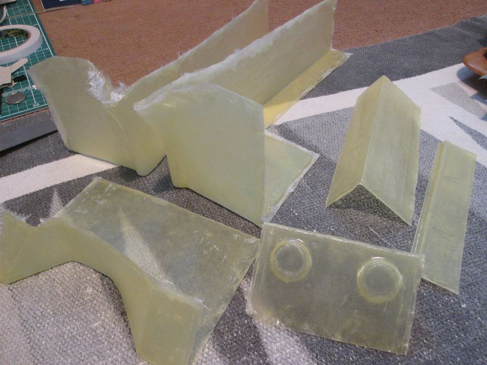 The sidepod sections were extended to meet up with the sides of the cockpit tub, and I wanted to re-cut the front edge where the nose will fit. The dashboard top now closes off the entire area below the windscreen in a single layer - once I started playing around with the previous panel and the main cockpit section I was concerned that I might not have much space to work with, so I couldn't rely on being able to add extra thickness. The front brake duct mounting fits across the front of the tub and also provides some location for the main nose itself: 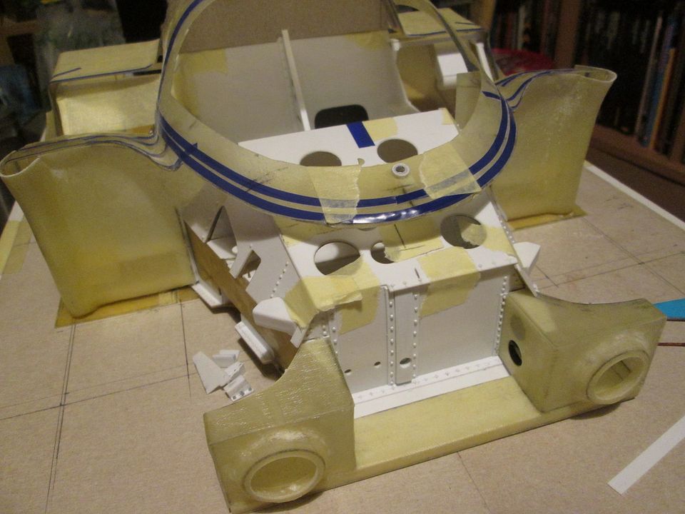 I briefly thought about trying to mould this piece from a single mould, but after making a cardboard mock-up it was clearly going to be easier to make it in sections and build it on the car. The tubular noseframe sits inside this structure, but although I've started making some of the mounting hardpoints for this I can't complete it until the nose itself is more advanced. You can also see here that the new sidepanels have been given an initial trim and now close-off the whole area behind the wheel - I'll return to these shortly. With the main cockpit section now fitting more reliably I could adjust the curvature of the windscreen roll-cage section, and start trimming the dashboard to fit around it all: 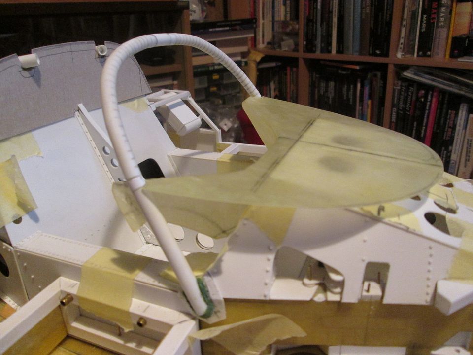 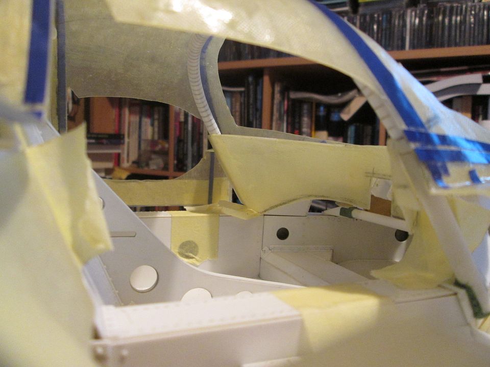 What's not clear in these photos is that I've fitted a mounting channel between the top of the tub and the underside of the dashboard. This gives me reliable positioning, and will eventually probably be magnetised to fix it in place during the later stages of the build. Creating the sections of bodywork which link the sidepods to the side of the tub was not an easy job. I spent some time on this earlier in the summer mocking things up in cardboard to get a feel for the shape, but I couldn't work out how I could do it as a single moulding. So, I gave up on this idea and made them from sections of flat fibreglass sheet instead: 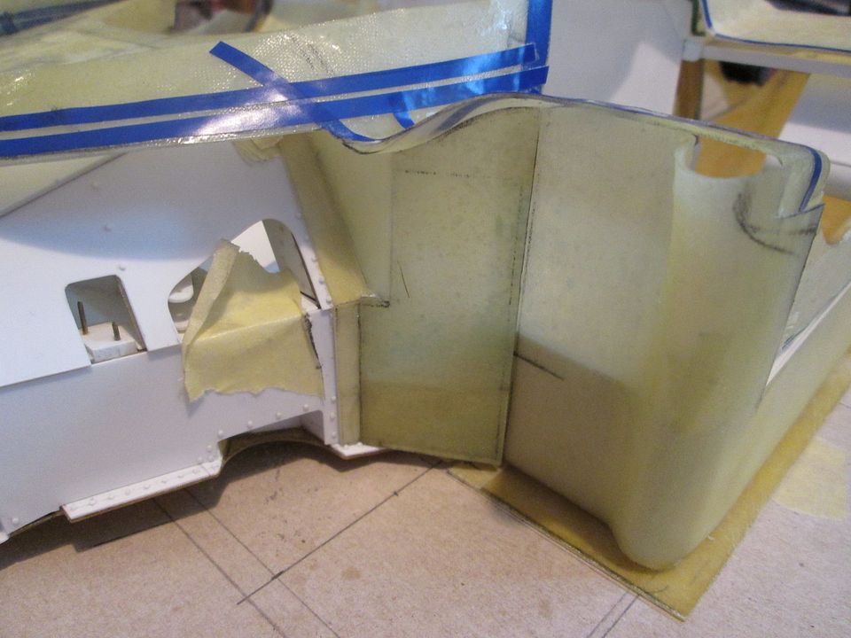 When I'm happy everything is 'just so' I'll probably glue the two sections together, then add a couple of layers of fibreglass to smooth out and reinforce the joint. The top edge has been trimmed and fettled to suit the curve of the top section, and I still have to work on the outer corners where the nose locates. The doors also hinge in this area, so that's not a job I'm looking forward to tackling! For a change of scene in the run up to Le Mans I decided to make the foam tyres. The method was identical to the 935, so I won't go into too much detail again, but they were all made on a pillar drill with an adjustable hole cutter, a single drillbit, a long 1/4" bolt, some emery cloth and abrasive paper, and a foam sanding pad. Stage 1 - put a pilot hole through from each side, then use the adjustable cutter to create the outer diameter and the inner diameter. Hopefully when the tyre is removed from the main foam block the two sets of cuts vaguely line-up with each other... 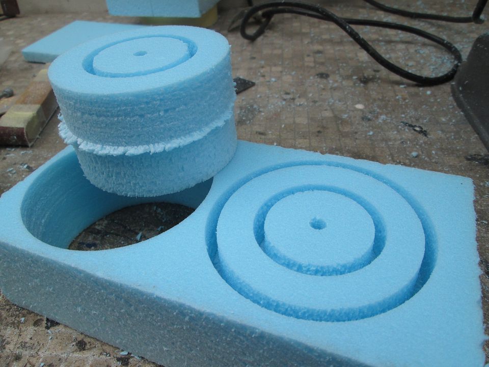 Stage 2 - mount each tyre on the long bolt, then smooth everything out to the desired shape using the foam pad and emery cloth: 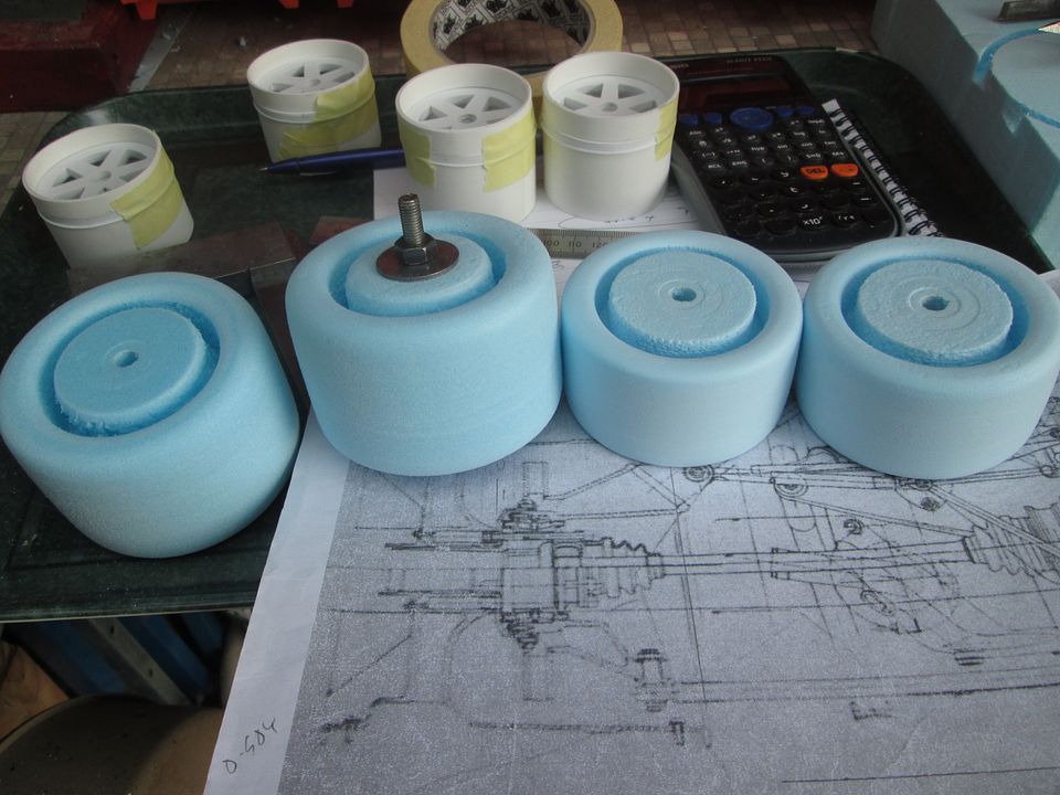 Stage 3 - after removing the centre core from each tyre, adjust the internal diameter by hand to suit the wheel centre components: 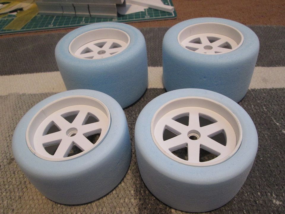 Stage 4 will be to do a final adjustment of the wheel overall widths, and make some rim edges to tidy everything up. The wheel centres need a bit more detailing, and there's also the question of adding cooling covers, etc, but this is for a later date. The next couple of jobs were something I had to address before moving on with the project, but fitted into the 'I'll do that later when I've got a better idea of how to do it' category! Firstly, I'd over-trimmed the back edge of the nose where it meets the edge of the windscreen, so I needed to extend the flange in order to re-cut it: 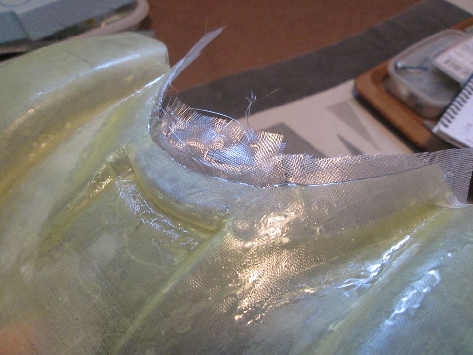 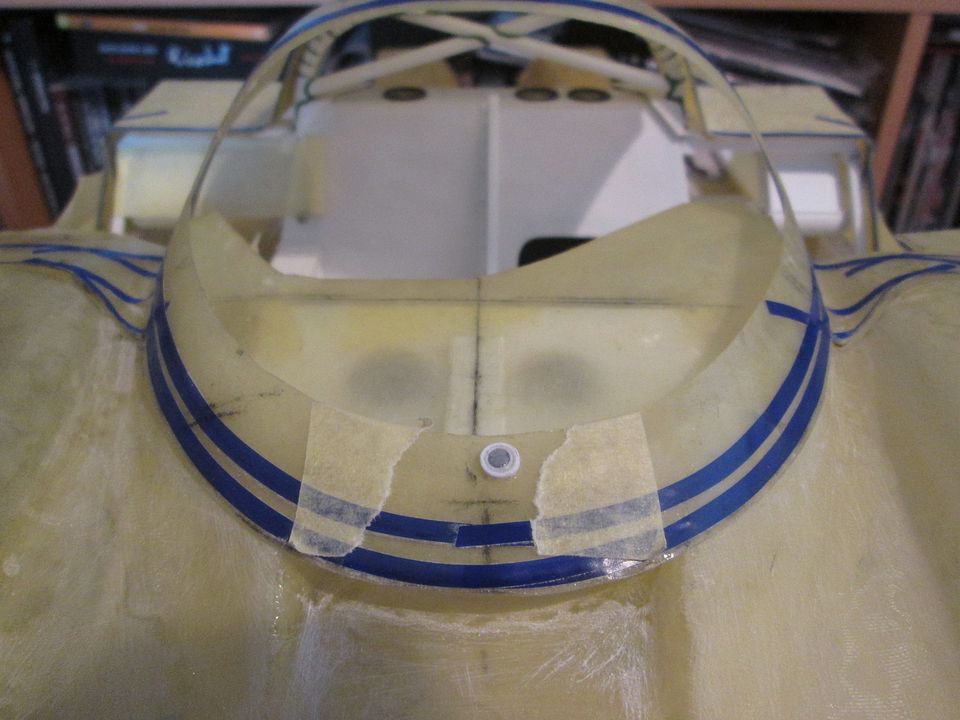 My first thought was to create a flange from cardboard and lay-up onto that, but after much head-scratching and no progress, I simply put the nose back on the mould! I put a couple of layers on from the outside, and then added a couple more on the inside. At most I barely need about 3mm extra, so most of this new flange will eventually be removed. I also used this opportunity to cut a small section out of the mould to extend the cockpit air inlet duct under the edge of the screen surround by about 5mm. The other job was to do something about the rigidity of the main cockpit section. Having marked out the panel lines in tape on the outside, the obvious solution was to add a layer or two to the inside: 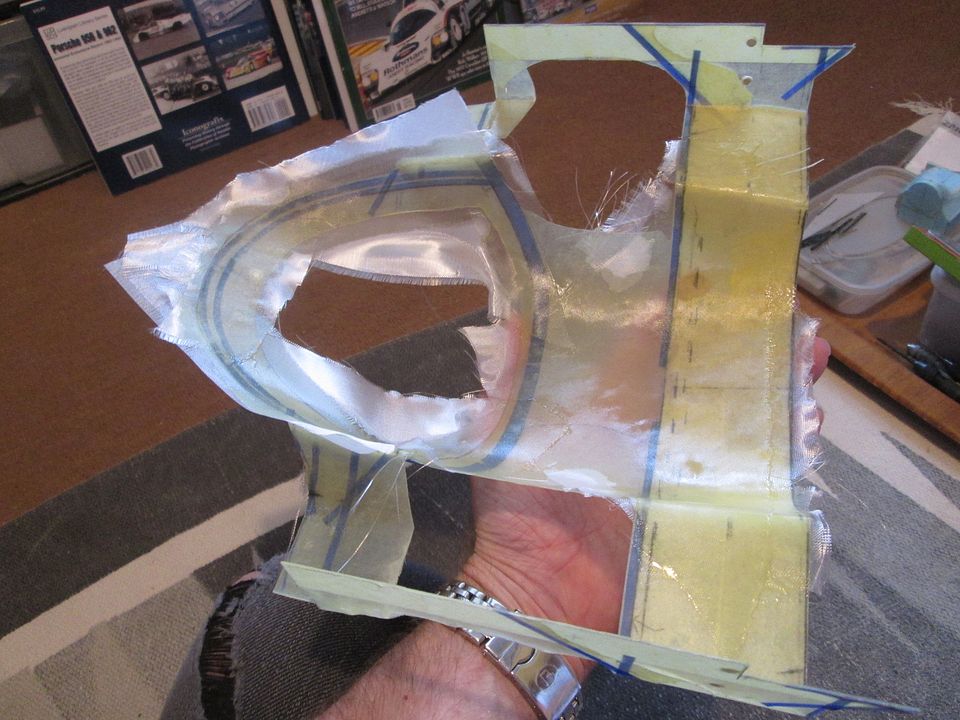 I've used the heaviest-grade cloth for these extra layers, each one adding about 0.2mm of thickness (and stiffening things up nicely!). I've checked everything still fits - it does - so it's now a case of tidying it all up and getting ready to cut out the rest of the door openings, etc. I'm still toying with the idea of bonding some stiff wire into the screen surround, as the A-pillars are going to be really thin once it's all trimmed-out. If I can do this without distorting the whole panel or fouling the roll-cage tubing, I'll probably do it. Last job for this update - I started working on the main inlet ducts into the side-mounted rads and coolers. It's another one of those areas which varies slightly from car to car, year to year, so it's hard to get enough photos of a 'definitive' arrangement. Again, instead of making these as moulded parts I'm putting them together using pieces of flat fibreglass sheet, offcuts of old panels with 'folded' edges, etc: 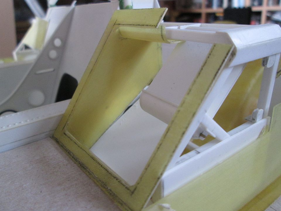  It's still very much work-in-progress, but I've done enough on this side to be happy it'll all hang together, and will probably start on the other side later this week. Still lots to do, and it all needs to be tied-in with the sidepods and panelling eventually. Sorry it's been another lengthy one tonight - I can't believe it's nearly the end of August! All the best, SB |
|

|

|
|
08-23-2021, 03:49 PM
|
#107 | |
|
AF Enthusiast
Join Date: May 2009
Location: Tucson, Arizona
Posts: 1,469
Thanks: 12
Thanked 126 Times in 120 Posts
|
Re: 1/8 Porsche 956
Never a need to apologize ScratchBuilt
Your work is just AMAZING - I've said it before so it sounds repetitive - What you are able to do with raw building materials is simply AMAZING. You are a true model craftsman on this website - the most that the rest of us can do is build a kit that is all designed and just needs assembly and paint. Your work creates everything from raw styrene and fiberglass and putty and some metal. You truly are a master model builder ScratchBuilt - I will bet that the real cars you work on are just fantastic rebuilds and restorations. Cheers John |
|
|
|
|
|
09-13-2021, 02:23 PM
|
#108 | |
|
AF Enthusiast
Thread starter
Join Date: Nov 2008
Location: Norwich
Posts: 649
Thanks: 21
Thanked 111 Times in 87 Posts
|
Re: 1/8 Porsche 956
Making progress!
I've been concentrating on the windscreen surround area since the last update - mainly because this is a major roadblock stopping lots of other jobs until it gets done! First task was to trim the windscreen edge to the desired shape:  ...while still making sure that the roll-cage and dashboard panel fits properly, of course. Despite the extra fibreglass cloth bonded into the inside of the shell, I felt it should be stiffened further. So, I added a crescent-shaped flange around the front edge, cut from flat fibreglass sheet:  The tape across the A-pillars kept everything in the right place while I trimmed and fitted the flange. The end result was a noticeably reinforced shell, and a useful flat surface around the base of the windscreen surround which I could use for the next job...  ...which was to add the lower extension, including the inlet openings for the cockpit ventilation. I made this section in styrene as it was going to be too awkward to mould it, then lay-up in fibreglass. If it was just the vertical curved face it wouldn't have been a problem, but it also has a horizontal flange: 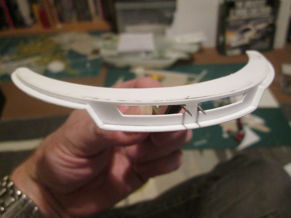 This piece will eventually be glued to the windscreen reinforcing flange, then the joint filled with white putty or Greenstuff. Adding these extra pieces to the cockpit bodywork potentially complicates the process of fitting and removing the shell with the dashboard panel in place, so I've been doing some subtle trimming to still allow the shell to be lifted off. After getting the screen opening trimmed to shape, the next step was to add a small flange around the inside to give me something to glue the screen to. Plan A was to make a flange in styrene (preferably black) but the curvature around the top edge pushed the flange out at the wrong angle. So, Plan B was to make a flange in fibreglass - just a couple of layers - and then fit this in place. I would also need similar flanges for the door openings, etc, so the fibreglassing extended a bit... 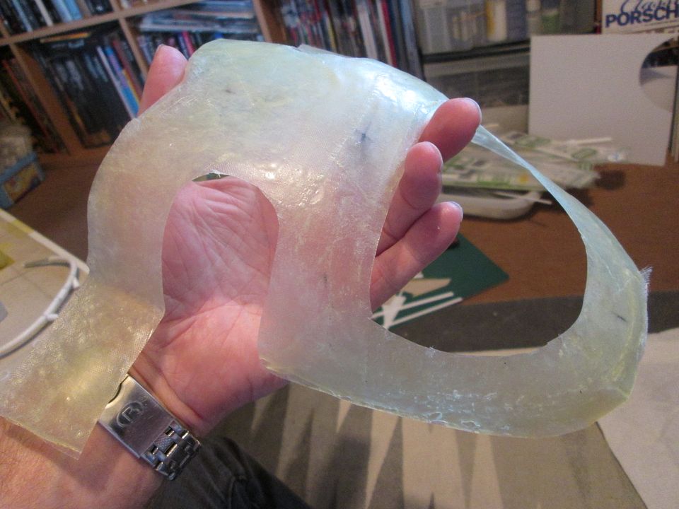 I was expecting to have to cut-and-shut the flange because of the size reduction inside the shell, but it fitted perfectly and looks the part when trimmed: 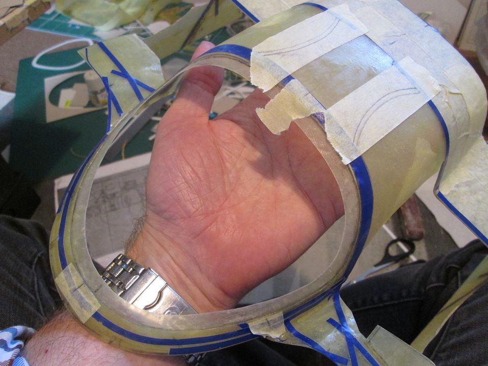 In this photo you can also see the start of the next job - opening up the doorframes. I've been leaving this until I felt the bodywork was strong enough, and with the extra layers of cloth and the flange, it's as strong as it's going to be. I can't add a wire without it interfering with the main roll-cage, so I'm relying on the fibreglass until everything is ready for final assembly. I've left a bit of room for adjustment at the top, but the front and rear edges are basically where they need to be: 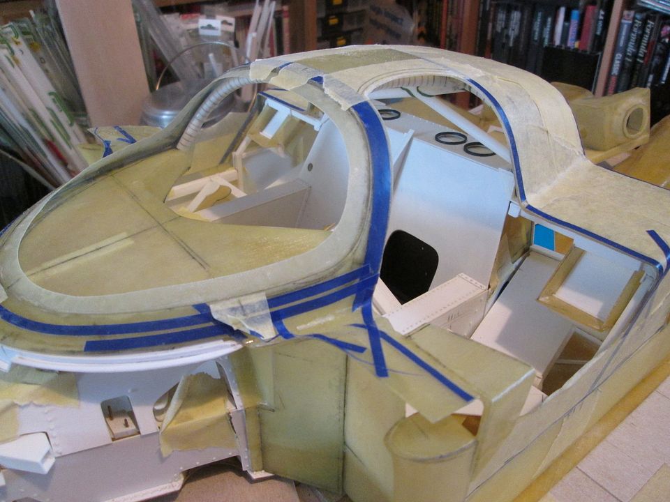 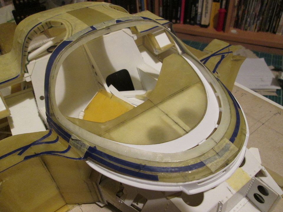 In this final photo you can see another piece of the dashboard assembly - the white styrene panel around the inside edge provides the slots which feed air from the bonnet duct to the inside of the screen. There'll be a fabricated duct piece between the top of the tub and the underside of the dashboard panel - I'm working on this now. This will also provide extra support for the front end of the bodywork. So, definitely making good progress. I don't want to cut the final connecting pieces across the base of the door openings until the shell is absolutely fixed in position, so this has got to be one of the next jobs. Then I can start looking at trimming the doors to fit the openings, and adding the balsa-reinforced outer panels. Even if I don't lay-up any more fibreglass this year, I have enough parts available to keep me busy through the winter - doors, tail, engine undertray, etc. have a good week, SB |
|
|
|
|
|
09-24-2021, 04:09 AM
|
#109 | |
|
Blarg! Wort Wort Wort!
Join Date: Mar 2006
Location: Quezon City
Posts: 2,120
Thanks: 64
Thanked 101 Times in 100 Posts
|
Re: 1/8 Porsche 956
great stuff!
__________________
olly olly oxen free |
|
|
|
|
|
09-27-2021, 02:29 PM
|
#110 | |
|
AF Enthusiast
Thread starter
Join Date: Nov 2008
Location: Norwich
Posts: 649
Thanks: 21
Thanked 111 Times in 87 Posts
|
Re: 1/8 Porsche 956
Hello again,
Two weeks between updates - what's going on?! Well, I've been getting on with the various jobs and gluing things together, so there's work to be shown. First up, here's the 'duct' section that fits between the top of the chassis tub and the underside of the windscreen surround: 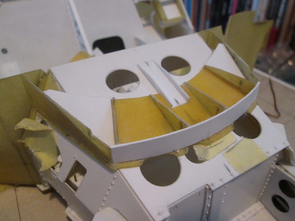  Ideally I would have made it all from fibreglass but didn't have a suitable scrap section with the right curvature for the front, so that's 0.75mm styrene. The reinforcement on the inside will all be buried under the dashboard top, so only the outer faces will be visible. At some point I'll smooth out the joints between the panels with greenstuff so it looks like a moulded part; then it's ready for prepping and painting. The next job was to finally magnetise the sidepod panels onto the support frames. As with the main bodywork, these panels will eventually be glued in position, but being able to fit and remove them easily during construction is proving to be very useful. I've used two pairs of 5mm x 1mm magnets on the front of each pod, with a solid mounting into the box-section support frame on each side:  I glued a piece of thin 0.25mm styrene sheet to the inside of the fibreglass panel so that I could do the final gluing of the magnet panel using liquid poly glue rather than CA. I didn't want to risk the CA going off too quickly with the panel in the wrong position... By the time of this next photo I'd also glued the inner wheelarch panel to the sidepod: 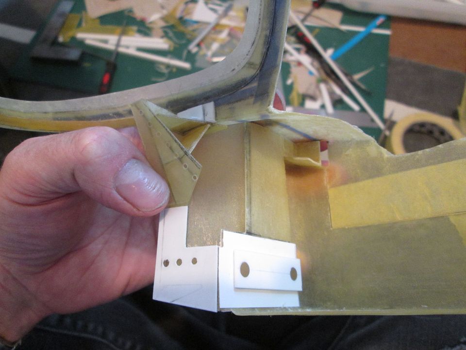 So now each sidepod is a single piece from where it meets the tub by the dashboard, back to the rear wheels. This also meant that I could add some extra 3mm magnets to attach the base of the windscreen surround to the top of the inner wheelarch section:  ...and I could also extend the outer corners where the door pivots, and add more small 3mm magnets here to locate the outer ends of the top body. There's now eight pairs of magnets holding the top bodywork in place, plus the two pairs in the front of each sidepod. I'm now considering my options for how I can magnetise the main floor panel and rear venturi section - I can drill through the sidepods and attach something to the inner frames, or I can do everything fibreglass-to-fibreglass. Using the inner frames will probably be Plan A. In this final photo you can see that I've removed the sections of fibreglass blocking the door openings. I didn't want to do this until I'd magnetised the front of the top bodywork (and added some reinforcement). With both these jobs now completed, it was time to open things up: 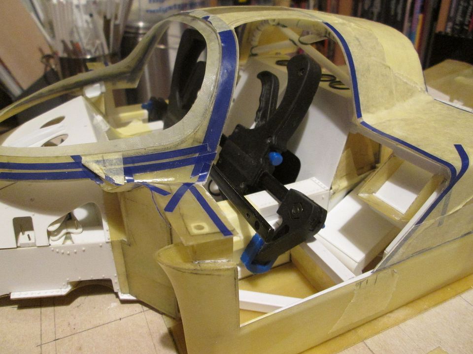 I've started offering up the door panels and doing some initial trimming to get them closer to size, but that's an on-going job. I've also filed the edges of the door openings to a 'final' spec. The A-pillar around the windscreen is maybe 2mm wider than it should be, but at the moment I'm prepared to leave this as it is and accept the slightly narrower door. I'm reluctant to take any more strength out of the bodyshell! That's it for tonight. The bodywork trimming and fitting will continue for a while yet, but it will be nice to get the doors underway then spend some time on something else for a while. The wheels haven't had any attention since I made the tires last month, or I could make some seatbelts, or maybe return to the engine / gearbox assembly...still plenty to be done. All the best, SB |
|
|
|
|
| The Following User Says Thank You to ScratchBuilt For This Useful Post: |
Petersm99 (04-28-2022)
|
|
10-25-2021, 03:03 PM
|
#111 | |
|
AF Enthusiast
Thread starter
Join Date: Nov 2008
Location: Norwich
Posts: 649
Thanks: 21
Thanked 111 Times in 87 Posts
|
Re: 1/8 Porsche 956
Hello again,
This update is short on images, but not short on progress. Following on from last time, I've been easing out the door opening and also trimming the two door panels to suit. Not shown, but I've also started adding a thin flange around the inside of the door opening... 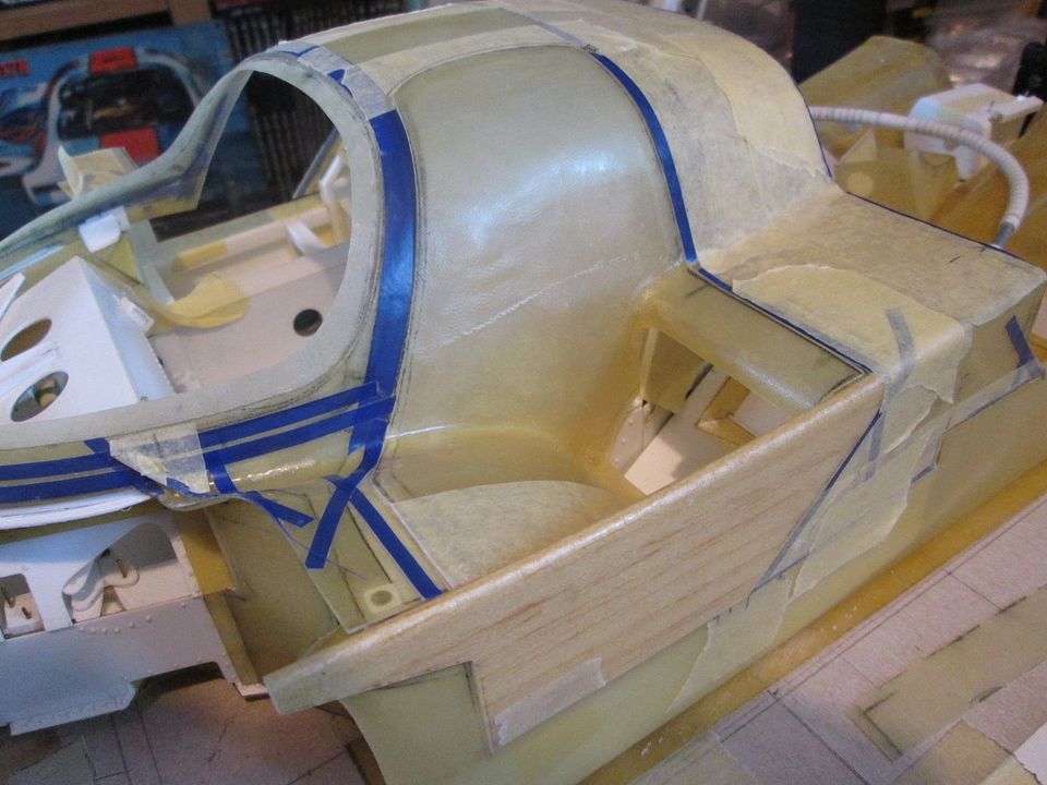 The outer panels with the balsa cores have been trimmed down to pretty much the final shape - I've left the front end unfinished as I need to work out what I'm doing with the hinges, etc. I haven't decided how I'm attaching the two sections together, either, but it'll need to be pretty robust - it may require some extra fibreglassing to reinforce whatever glued and pinned joints I create. After adding the magnets to the front end of the two sidepods, I wanted to use some more to connect the ground-effect undertray: 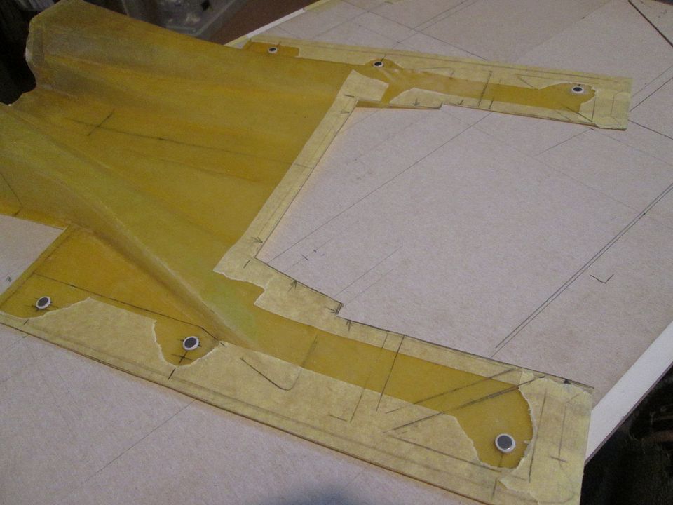 The two at the front will be accessible through the sidepods, and the rear four will be hidden in the engine bay under a series of false-floor panels. The only obvious issue with using magnets is that you can't do anything about the 1mm thickness. This doesn't matter for the ones in the sidepods, but in the engine bay I've been cutting various styrene plates to fit around the magnets and cover everything up - you'll be seeing these in various states in some of the following photos. Fortunately, this raised floor shouldn't have any knock-on problems, as there isn't really anything in there other than the two turbos and some ducting. So, I've now got the sidepods, undertray and tub all locked together with magnets. Everything comes apart and fits back together in seconds, which is very useful! Before moving on, I spent some time dummying-up one of the rear corners: 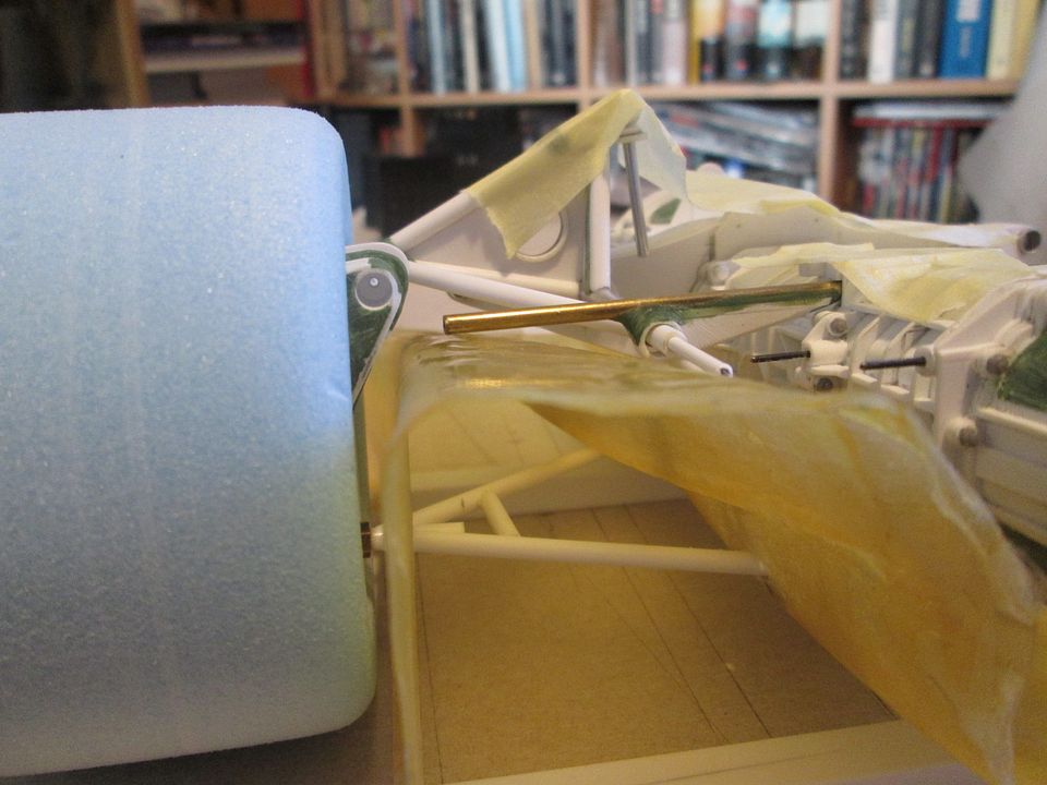 This has confirmed several things. Everything still clears the undertray, the top rockers will sit at the right level, and I can get the lower wishbone through the fibreglass. In addition, the rear edges of the two pods can now be trimmed back to the correct length, setting the position of the main wheelarch. With this confirmed, the next job was to create the two panels which will close-off the front of the wheelarches, and provide a solid mounting point for the main engine cover. These started off as 0.75mm styrene panels:  ...and were then made into a sandwich with a layer of fibreglass and another layer of 0.75mm styrene: 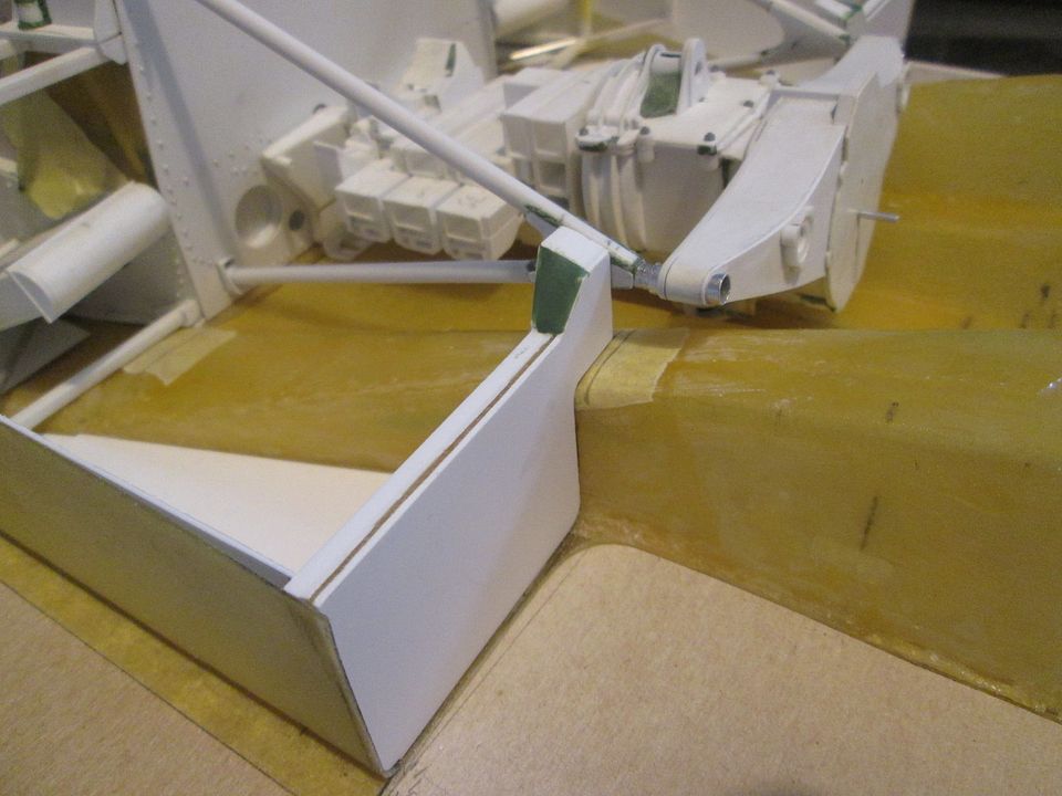 The inner ends meeting the A-frames were built up with styrene section, etc, then fettled to the correct width to centre the engine in the undertray. I've added a couple of small pins to help when it's all glued together, and there's some lengths of angle across the bottom which will tie-in with the platework in the bottom of the floor. In this final shot, you can see that I've added some bracket details on each of the two A-frames - these won't be pinned, but it all adds more area when it's time for gluing: 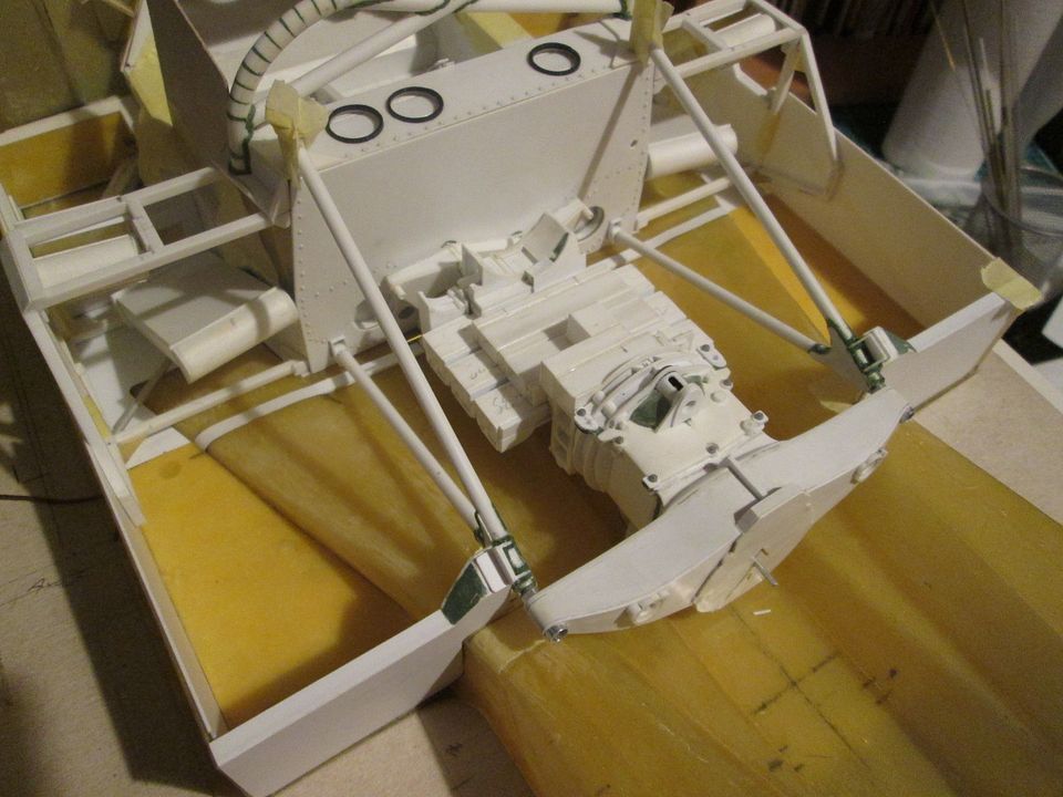 I've now cut the final two top plates for the undertray, so it's back to fibreglass across the whole width. The 956 undertrays were a mix of fibreglass or aluminium versions depending on the year and spec, so although I haven't decided on an identity for this car yet, it's running the fibreglass floor! The styrene strip running across the front of the engine bay is the start of some detailing for the joint between the panels. I still need to extend it out to the sides, and add some fixings. Hidden by the block, there's an angle bracket which slips onto the lower corners of the engine mounting and provides extra support for the undertray. So, that's where I'm up to. More next time! SB |
|
|
|
|
| The Following User Says Thank You to ScratchBuilt For This Useful Post: |
Petersm99 (04-28-2022)
|
|
12-19-2021, 11:10 AM
|
#112 | |
|
AF Enthusiast
Thread starter
Join Date: Nov 2008
Location: Norwich
Posts: 649
Thanks: 21
Thanked 111 Times in 87 Posts
|
Re: 1/8 Porsche 956
Hello again,
Not quite the usual end-of-year tidying-up post - that'll appear on the 31st. This update is more the realisation that I've got nearly two months of progress to show, and that I'll probably find a few things I've missed. So maybe there'll be another small update before the 31st... So, to start with, here's the main mounting brackets for the seatbelt shoulder straps: 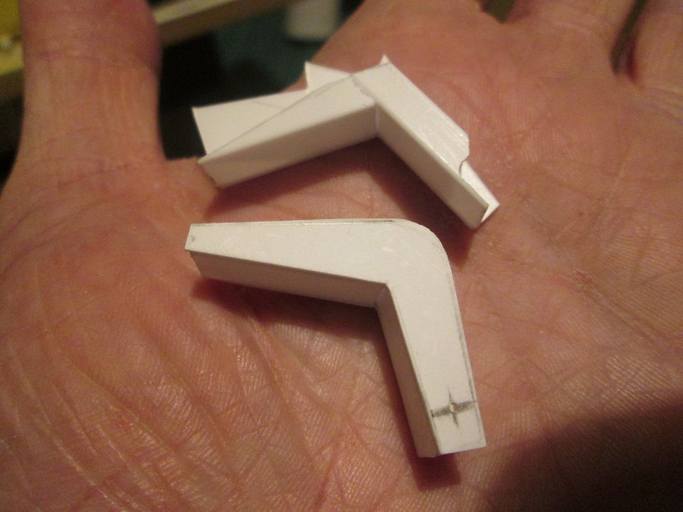 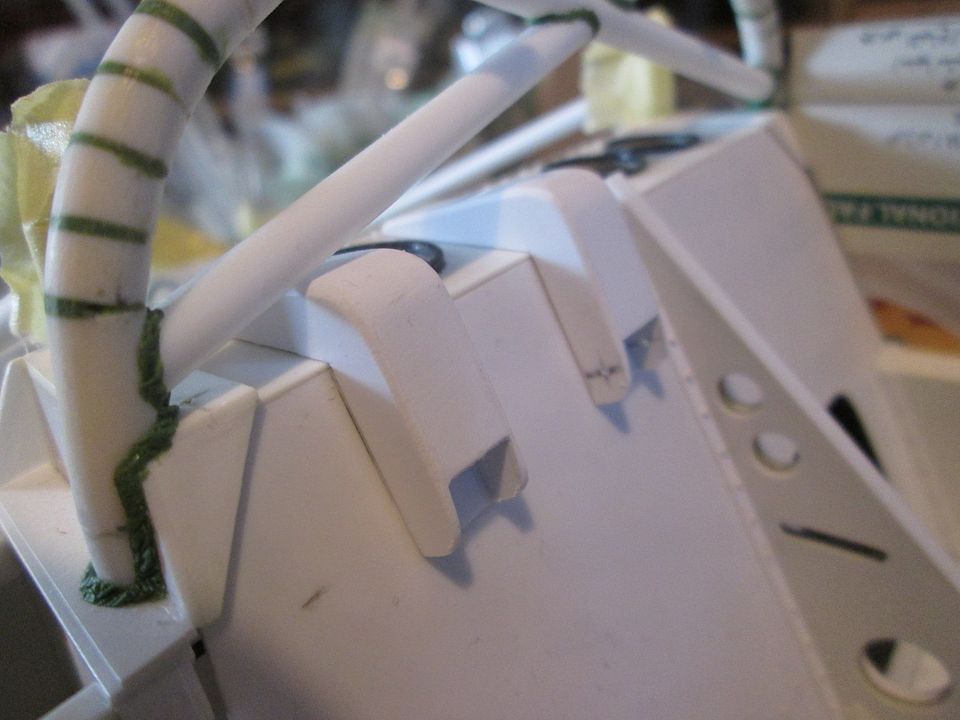 Each one is made from 5/16" x 3/16" box-section, combined with 0.75mm styrene side-plates and a curved top-plate to tie it all together. I've also made some more flanges-with-rivets which will be glued in place during final assembly. This was one of those nice little 'what am I going to do today?' jobs which can be very satisfying when you've been spending lots of time on something else and getting nowhere fast! In a similar manner, at the end of November I spent a day or two making the core of the main oil-tank: 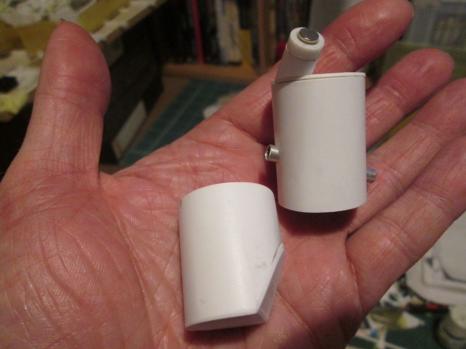 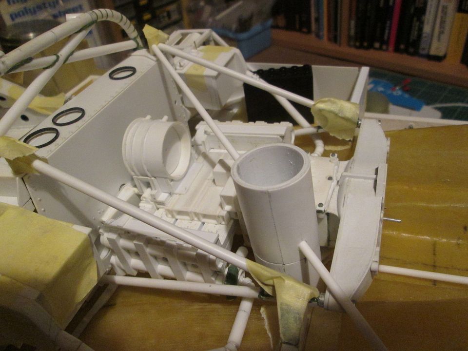 I made it in two sections for three main reasons. Firstly, I wasn't sure that my technique of gluing together multiple layers of styrene to create the body would work effectively over such a long length. Second, I knew that I would have to put the engine-bay bracing tube through it, so this made it possible I could ruin the whole thing. Thirdly, I wasn't totally sure about the overall length, and wanted to allow room for adjustment as I went along. Having made the two sections, each approx 26mm diameter, I cut the corner from the lower end and added the closing plate. This chamfer allows the tank to fit neatly against the side of the underwing. At the top, I made a dummy top-plate and filler neck section. Eventually I'll have to adjust the height of the tank and the filler neck to suit the engine cover, so there was no point trying to get this part right-first-time. I've set a magnet into the end of the filler neck so that I can get perfect alignment when it comes to putting the hole in the bodywork! The next job was somewhat more involved - time to put a locating flange around the front edge of the engine cover. My original thought was to do this in fibreglass - either freshly made, or by using parts cut from the original panel - but it was soon clear that this would not be practical. So, plan B - make the flange in styrene: 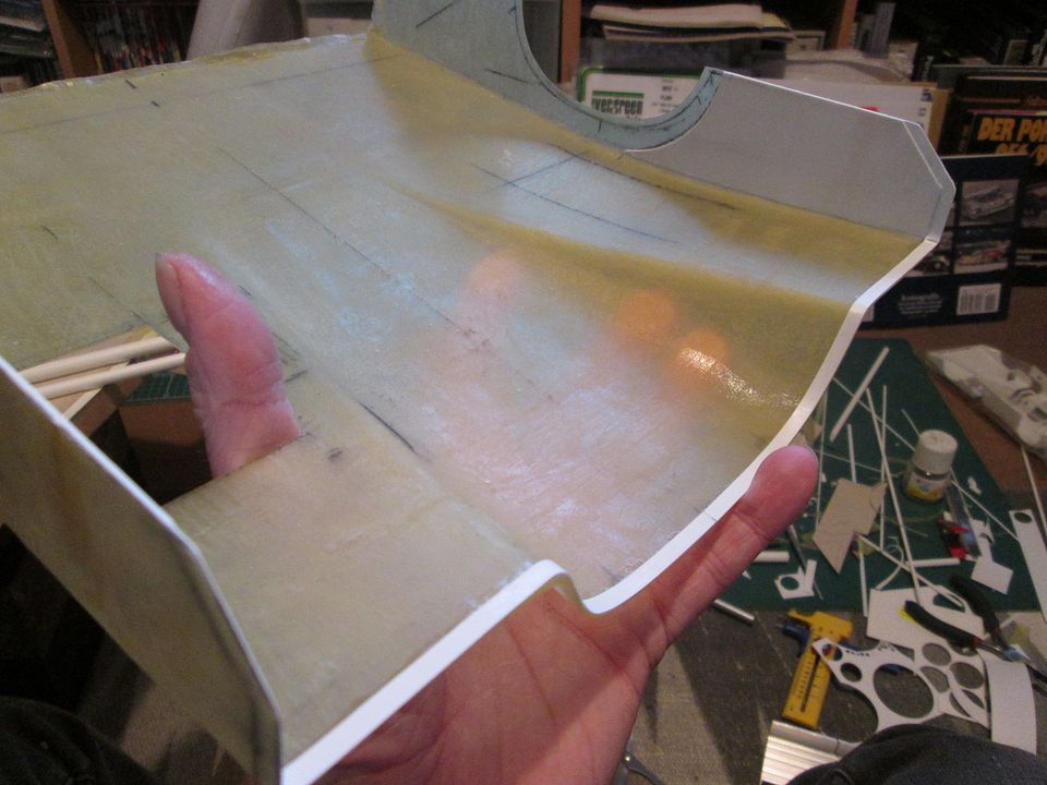 For the first part of the flange, I CA'd 0.25mm strip flush with the front edge. This would give me something I could glue to suing regular liquid-poly glue, making fitment of the further layers somewhat easier. You can also see here that I've put a pair of 0.75 panels on the sides ahead of the wheelarches - these will be used to stiffen the bodywork, and to help with locating the engine onto the lower bodywork. Also in this photo, you can see that I've started marking and cutting the holes for the exit ducts from the rads and coolers... Next, in combination with the 0.75mm inner plates I've added two fabricated channels which will locate onto a pair of angles set into the lower side panels. I've drilled and pinned these through to the inner plates for extra strength. 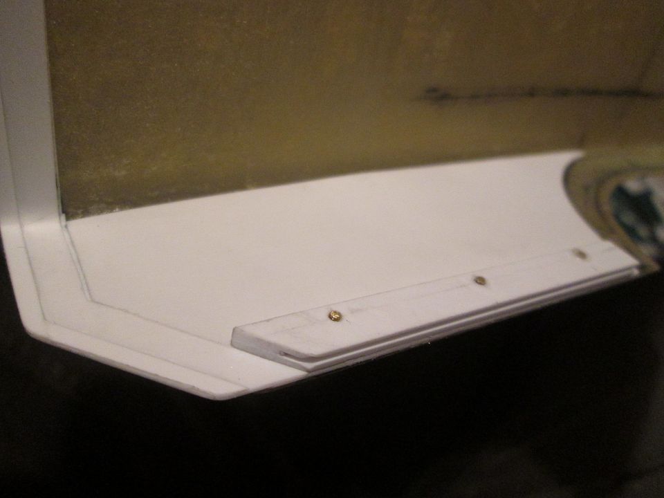 By the time of the next photos I've extended the stryene front flange using a combination of 0.5mm and 0.25mm styrene strip, added the magnetised blocks in the middle, and fitted the two main exit ducts: 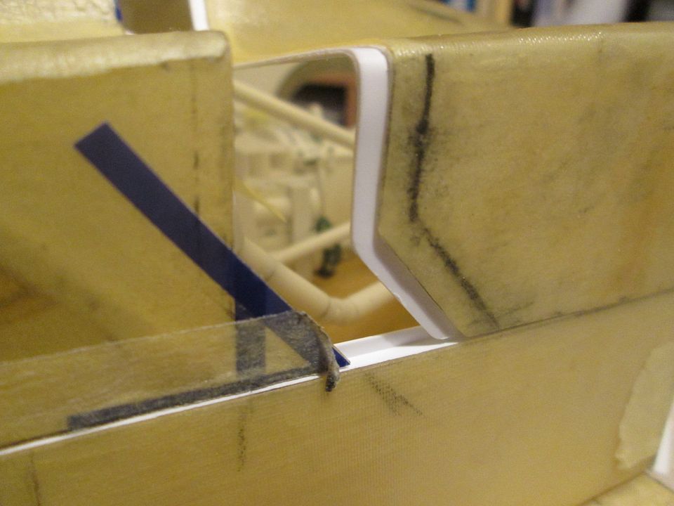  I've also started playing around with the ducting leading from the rads to the exit, as you can see on the left of the photo. This is proving to be slow-going - it's very difficult to decide if something fits properly when (a) you can't quite see what's going on and (b) the thing you're trying to line-up with (the rads) keeps moving as it's not secured properly! It's been a bit frustrating, and has led to me re-working the main radiator mountings - more on that next time. The last news for this update is that I've started making the pipework from the water pumps back to the intercoolers:  I've used 4.8mm styrene tube for the main pipes, with smaller tube inside and plastic-coated wire inside for the bends. Eventually the bends will be green-stuffed and smoothed over. The main sections are magnetised so the whole lot can be hung in place from the coolers without gravity taking over and pulling them apart! Rather than using rubber hose to connect these pipes, Porsche used solid 'Wiggins Clamps'. You can see one in the photo above, here are the other three:  A bit fiddly to make, and too much CA glue ended up on my fingers, but I'm happy with the results!  In this last photo the intercoolers are now mounted about 1/8" higher than originally. I've got the turbo units positioned where I want them, so I've had to adjust the pipework to make sure everything connects. There's still work to be done in this area, but getting everything in the right place first is half the battle. That's it for tonight. A few more days at work, then time for a Christmas break; I've got a few 956 jobs lined-up, and hopefully I'll be able to take another 'kit photo' on the 31st to get everything up to date. Have a good week, and a Happy Christmas. SB |
|
|
|
|
| The Following User Says Thank You to ScratchBuilt For This Useful Post: |
Petersm99 (04-28-2022)
|
|
12-21-2021, 12:33 PM
|
#113 | |
|
AF Newbie
Join Date: Oct 2020
Location: Netherlands
Posts: 57
Thanks: 7
Thanked 8 Times in 7 Posts
|
Re: 1/8 Porsche 956
Nice work SB.
I like the way u do the piping on your model. For making cilinder shaped items like your oil container i use the technique they also use on the inner roll of toilet paper. The advantage is that there will be less stress on the last glued edge of the styrene. see picture below what i mean.
__________________
Thx for watching,  Greetz Peter Greetz Peter
|
|
|
|
|
|
01-16-2022, 06:50 AM
|
#114 | |
|
AF Enthusiast
Thread starter
Join Date: Nov 2008
Location: Norwich
Posts: 649
Thanks: 21
Thanked 111 Times in 87 Posts
|
Re: 1/8 Porsche 956
...and we're into 2022 - a belated Happy New Year to you all!
My plans for the Christmas break didn't quite work out - not because of anything dramatic or health-related, just that I spent my time on one particular thing which has gone on...and on...and on. I always like to write myself a shortlist of possible 'things to do', rather than feel like I've wasted an opportunity afterwards. So, going into the break I was thinking I could maybe spend some time on the fire bottles, or do some more trimming on the tail section, or finalise the turbo installation and mountings...but I ended up working solely on the inlet manifolds and plenums! Despite the various drawings I have of the 956, there's not a huge amount of detail on the plenums which sit on top of the two inlet manifolds. Fortunately, there's plenty of photos available which cover most of the angles, and the installation itself pretty much determines how big they can be. The inlet manifolds would initially be similar to those made for the 935/78, but with the potential for changes later depending on the fuel injection used. First step with the plenums was a simple cardboard pattern to get a feel for the basic shape, then to make each one in an upper and lower half. The lower halves would include sockets to connect with the inlet manifolds, and a styrene core structure would provide a good base for the Greenstuff used to create the rounded sides: 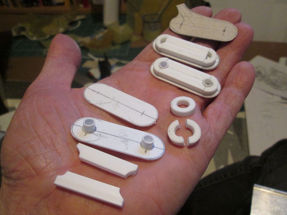 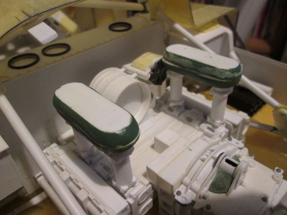 In the second photo you can see that the front end of the right-hand plenum is quite tight with the alternator and in potentially in danger of fouling the diagonal stay across the top of the engine. Yes, I was very aware of this! After this photo was taken I shaved about 0.75mm from the alternator body. What's not obvious from many of the photos you see of the 956 engine is that the front corner of this plenum is also chopped-off at an angle to match the diagonal stay. That's something I've done on mine later, too. Everything fits! The inlet manifolds are only pinned into the plenums at the front and rear - the centre inlet is only pinned into the head at the base. The connections between the three verticals have been drilled and pinned through and will provide the mountings for the throttle lever assembly. By this time the Greenstuff on the plenums had received a bit more attention, but I had not yet added the extensions which connect to the intercooler pipework. 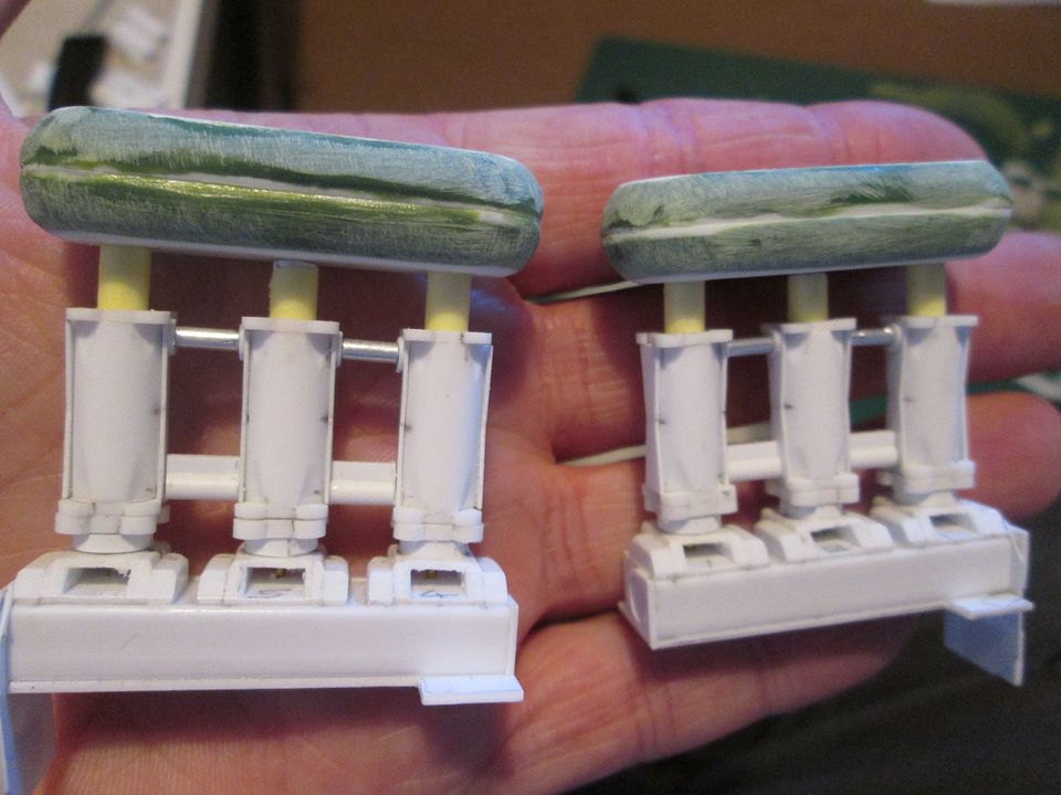 So, it was now time to make a decision: mechanical or electronic fuel injection? The manifolds for mechanical injection have a single downward-facing receptacle for the injector, but the electronic manifolds have two upwards receptacles. The initial run of works cars in 1982 all used mechanical injection (as per the 935/78), but the electronic injection was introduced in 1983. However, both types of injection were used on the customer cars in '83 - '85! As I haven't yet decided which livery I'm going to use for this project, I can't check to see which system that particular chassis was using. Photos showing what's fitted to a car now might not match what was used in period. I decided to go with electronic injection. It means I get to build some different bits for the fuel system, it makes the engine look different compared to the 935, and it's probably more widely-used than the mechanical system (although this is purely a guess!). I'm not going to worry too much about whether it matches the livery. Problem number one with building the injection system is that the fuel rails each side of the manifold need to hover in mid-air until everything is connected and mounted. To avoid inevitable frustration I made a simple jig which fitted onto the manifold and which would hold the two fuel rails while I made all the parts - everything in the same place, every time: 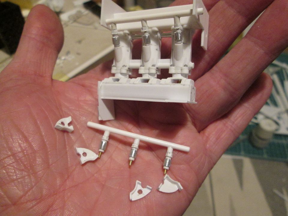 The fuel injectors are a mix of styrene and ali tube, some hex-section, and some flat discs, all on a central core pin through into the fuel rail. You can see that I've added the three upwards receptacles on the manifold this side, there's three more the other side, but at a higher height to provide clearance for the throttle mechanism. The four curved mounting brackets at the bottom of the photo are made from some cut-down channel section with extra bits of styrene added to build up the edge. It's all a bit fiddly for now, but I think it's working out okay - and will look even better with all the wiring, etc, added on final assembly. Last photo for this update is a late 'end of 2021' kit shot, taken earlier today. 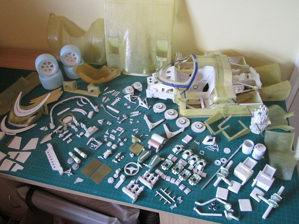 It's getting hard to fit it all into the frame! You'll notice that the two plenums are looking a little different, and there might be a few bits hidden away that I've not mentioned before. You'll also notice that there's a lot of bits here that haven't moved since the end of 2020... All the best, SB |
|
|
|
|
|
01-20-2022, 03:46 PM
|
#115 | |
|
Blarg! Wort Wort Wort!
Join Date: Mar 2006
Location: Quezon City
Posts: 2,120
Thanks: 64
Thanked 101 Times in 100 Posts
|
Re: 1/8 Porsche 956
Wow. Seeing the parts laid out like that just makes this build even more awesome.
__________________
olly olly oxen free |
|
|
|
|
|
02-21-2022, 02:41 PM
|
#116 | |
|
AF Enthusiast
Thread starter
Join Date: Nov 2008
Location: Norwich
Posts: 649
Thanks: 21
Thanked 111 Times in 87 Posts
|
Re: 1/8 Porsche 956
Hello again,
A mix of different things for tonight's update - didn't realise it was a month since the last one. First up, last month I continued working on the fuel rails: 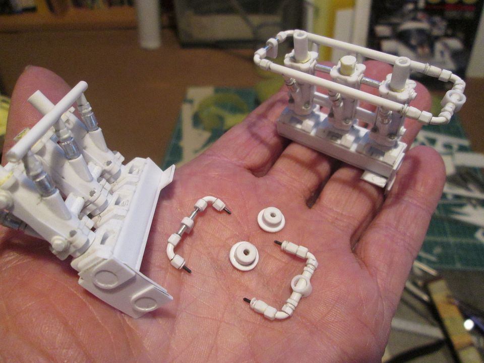 These still need more work - mounting tabs for the electrics, etc - and I'll probably need to adjust the overall length on the right-hand set to avoid clashing with the back of the alternator. Next, a selection of small items: 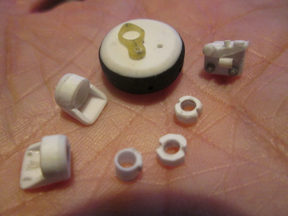 The large round piece (15mm diameter) is the early stage of the manifold pressure collector - this will mount onto the breather cover and sit above the fan shroud with pipes running to all six inlet manifolds. Sitting on top is the engine lifting eye - I shaped this from flat fibreglass to give it a bit more strength. Everything else is from the throttle mechanism - a pair of mounting blocks to take the cross-shaft, a pair of clamping rings, the cam for the throttle position sensor, and the TPS itself. Next, the engine breather cover: 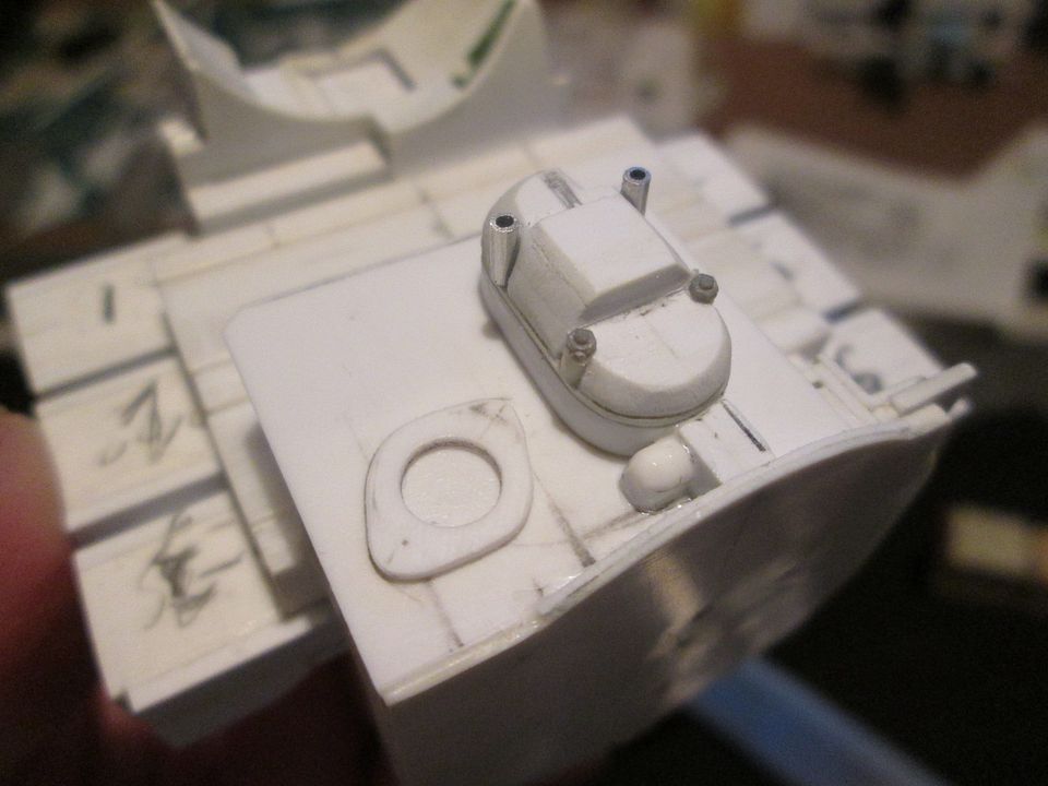 I started making this part as a copy of the spec used on the 935, but I later realised that the 956 version is different. That's what happens when you spend all day watching the Rolex 24h online from Daytona and don't check your reference photos! No big deal, I can probably use it when I put together the second engine... The manifold pressure collector will eventually sit on the two small ali tubes, and overhang the throttle cross-shaft. I've also added a bit of detailing to the top of the block with some webbing and the thermostat cover. The last couple of weeks have been a return to fibreglassing. I wanted to make the fan shroud and the inlet duct that hangs down from the roof of the car. I re-used the shroud mould from the 935-78 (after checking that nothing on the new engine had changed!) but extended the edges with some box-section to give me more options when trimming. I also did some subtle re-shaping on the curve around the back of the fan in order to make sure there would be plenty of clearance on the throttle mechanism. 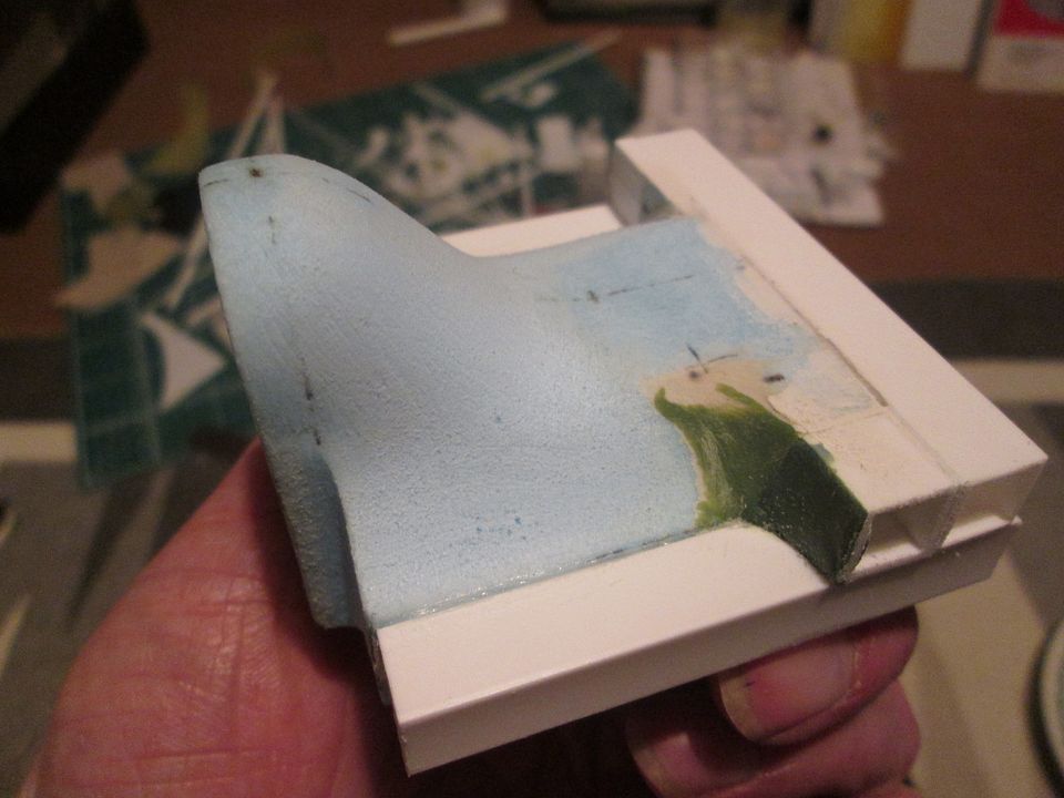 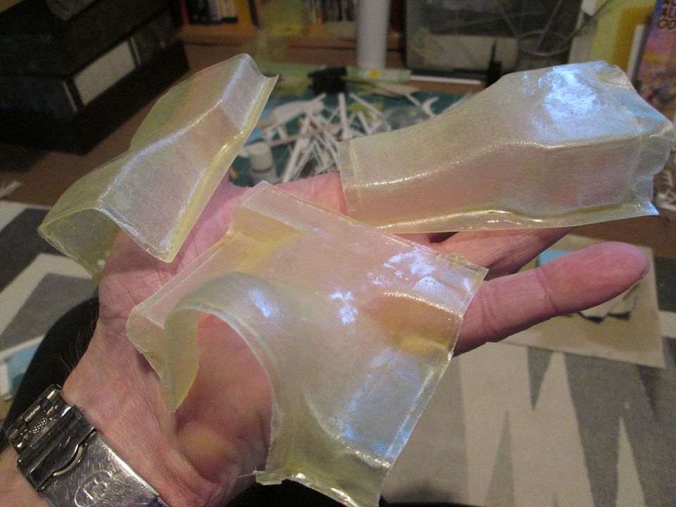 Trimming the fan shroud was not a five-minute job... 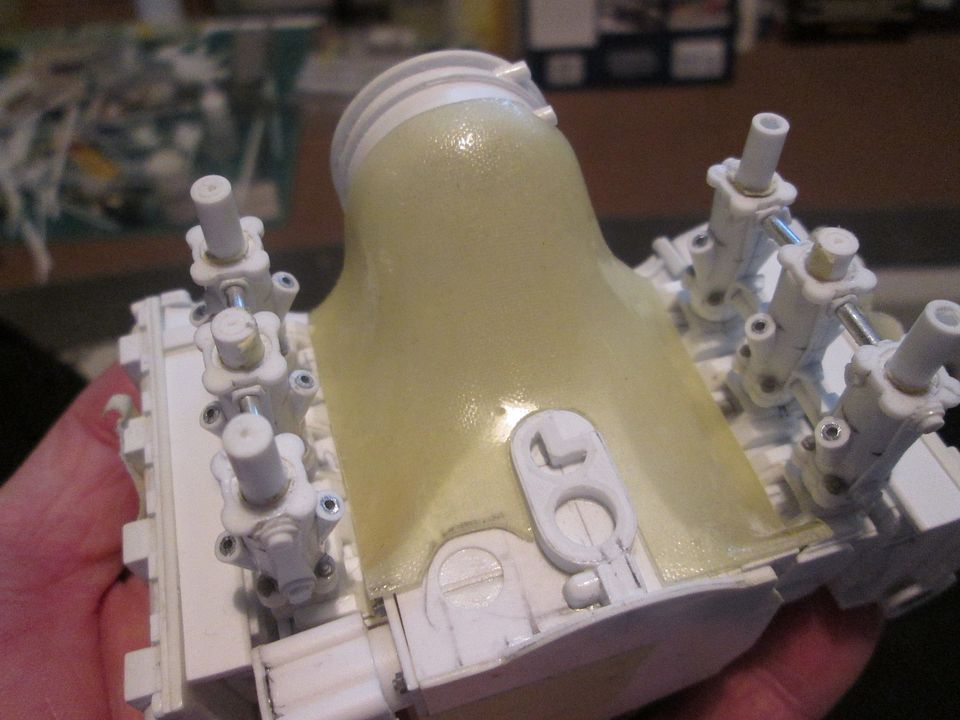 Cut, file, check, file, check, file again, check, rinse, cut, repeat, for several hours! I must remember to mark the shape on the mould for next time. As well as trimming the fibreglass, I also had to re-shape the top edge of the styrene fan housing to allow the curve of the shroud to fall away. The other two pieces of fibreglass will go together to create the ducting that feeds cooling air from the roof to the engine: _956337.JPG?width=960&height=720&fit=bounds) Again, it took a lot of trimming and fettling to get it to this stage, but it's still a work-in-progress. I added all the styrene in the upper section as reinforcement and to make it easier when gluing the two halves together.  This last photo gets me back up-to-date, taken on Sunday. The ducting has been glued and pinned so that it can be located onto the back of the chassis tub. The blue foam piece on top is the pattern for the NACA duct and inlet that will be grafted into the roof panel - this week's main project is to make the inlet, and a second fan shroud. If I was keen I'd also make the NACA ducts for the rear deck at the same time, but I think these can wait for later! That's it for today - more next time. SB |
|
|
|
|
| The Following User Says Thank You to ScratchBuilt For This Useful Post: |
Petersm99 (04-28-2022)
|
|
02-22-2022, 04:04 AM
|
#117 | |
|
Blarg! Wort Wort Wort!
Join Date: Mar 2006
Location: Quezon City
Posts: 2,120
Thanks: 64
Thanked 101 Times in 100 Posts
|
Re: 1/8 Porsche 956
Amazing update as always!
__________________
olly olly oxen free |
|
|
|
|
|
02-22-2022, 01:26 PM
|
#118 | |
|
AF Newbie
Join Date: Oct 2020
Location: Netherlands
Posts: 57
Thanks: 7
Thanked 8 Times in 7 Posts
|
Re: 1/8 Porsche 956
Nice work on the engine fuel system, is there also a connection between the left and the right system or are they seperate from each other.
Your fibre glass works are awesome and nice to see U can use your old models for this build.
__________________
Thx for watching, Greetz Peter
|
|
|
|
|
|
02-22-2022, 02:50 PM
|
#119 | |
|
AF Enthusiast
Thread starter
Join Date: Nov 2008
Location: Norwich
Posts: 649
Thanks: 21
Thanked 111 Times in 87 Posts
|
Re: 1/8 Porsche 956
The fuel supply is effectively independent to each side of the engine. There will eventually be a pair of fuel filters mounted on the back of the cooling fan shroud, each one receiving a feed from the bank of fuel pumps in the cockpit. The fuel is fed to the T-piece on the front of each set of inlets, along both fuel rails, and to the pressure regulator on the back. The two pressure regulators are then connected with a single return feed to the fuel tank.
The fuel system on the original mechanical injection cars is somewhat simpler, with a single feed to the pump and then six pipes to the manifolds - basically the same arrangement as on the 936, 917, 908, etc...just a varying number of pipes! SB |
|
|
|
|
|
04-06-2022, 03:24 PM
|
#120 | |
|
AF Enthusiast
Thread starter
Join Date: Nov 2008
Location: Norwich
Posts: 649
Thanks: 21
Thanked 111 Times in 87 Posts
|
Re: 1/8 Porsche 956
Hello again,
More fibreglass parts tonight! Following on from the last post, I laid-up the main roof-duct in two parts - easier to make the back panel as a separate piece and trim both to suit: 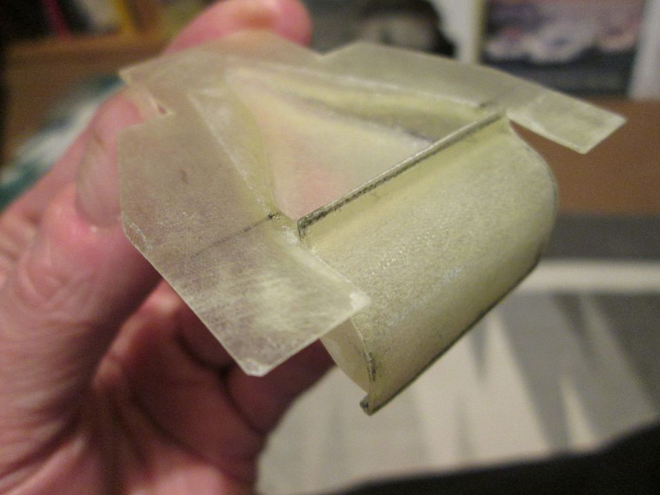 The large flanges made it easy to glue the trimmed duct into the roof, and I added a single layer of the lightest fibreglass cloth to bind everything together. I've put magnets into the two sections to allow for quick fitting and removal during the build process, and I won't have to fiddle around with multiple pins while I'm doing it. 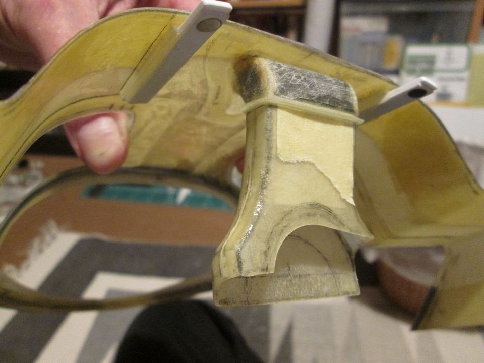 On the outside, before gluing the duct I added a mesh grille into the bottom of the inlet: 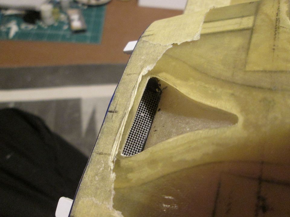 This may not be totally correct, but I can't imagine that the main duct goes right through to the engine without something in there to stop rubbish, small animals, etc, being drawn through! It also camouflages the fact that the lower section is blocked, but that's purely a coincidence... While making the roof duct I also made the three inlets for the rear brakes and the gearbox cooler: 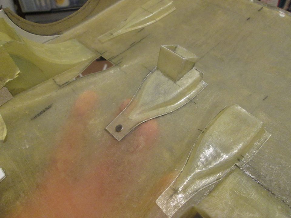 You'll see these appearing in several of the following photos - lots of trimming, fettling, positioning, re-positioning, etc. Extending the duct to suit the gearbox oil cooler was 'fun' - trying to work on it with the tail in position on the car, without the oil cooler in place, and with limited access (even at 1/8 scale). It would have been impossible to mould it in one go from the start, though, so this was the only way to do it. For a change in direction, I started looking at the fibreglass under-tail panels. First job was to mock it up in cardboard to get a feel for the overall shape: 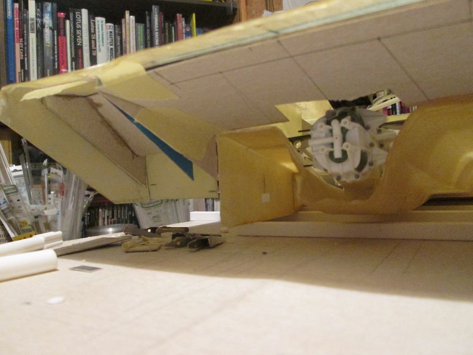 This whole process would involve a lot of trimming, snipping, lining-up, and general refinement to get things looking right. I'm particularly happy with the fact that the line of the top of the diffuser tunnels continues correctly to the edge of the tail, so that bodes well for later. Here's the rough-cut panels: 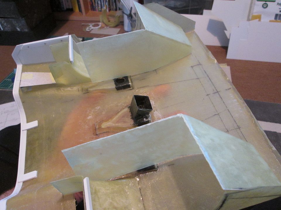 ...and with some trimming to incorporate the wheel-arch liner panels: 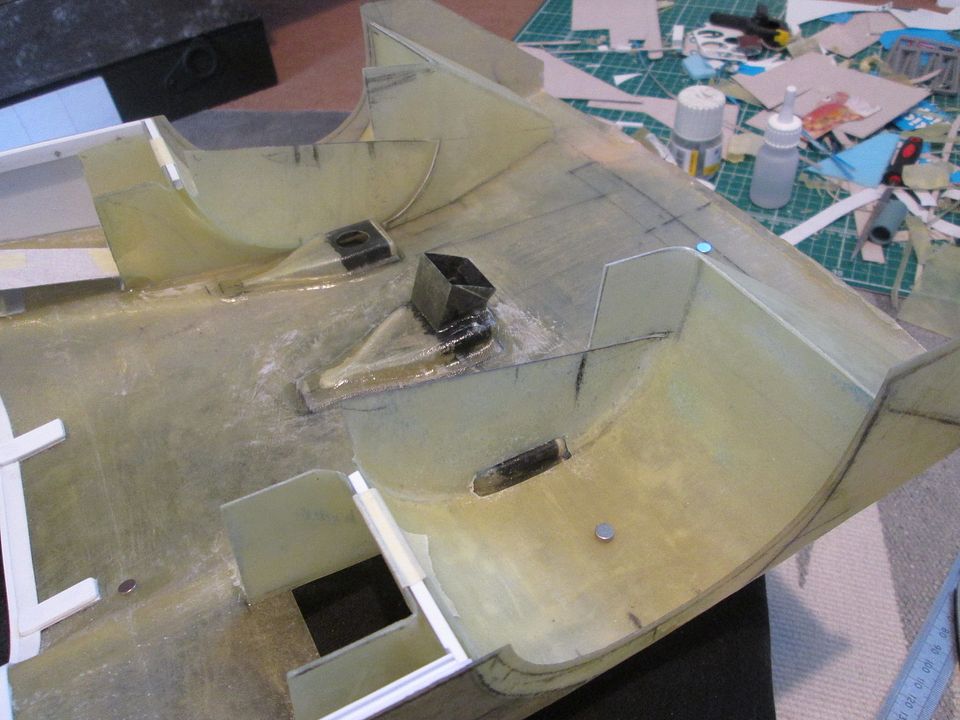 The magnets have been very useful throughout this part of the build, holding various parts in place. You'll note that I've trimmed out a slot in the wheel-arches to clear the brake ducts - this will be fibreglassed-over in time. Before fitting the undertail panels I wanted to stiffen-up the main shell. I wanted to keep this reinforcement fairly low-profile to make sure that it didn't foul the tail supports or the air-jack (both of which have yet to be made), so the solution was two lengths of 4mm brass tube: 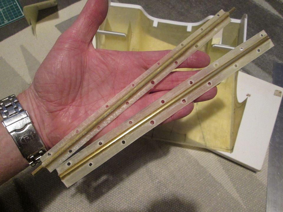 The fibreglass bits were left-overs from the 935-78, intended to replicate the way the tube-frame was bonded to the floor panel in the cockpit. I CA'd the rods into the fibreglass and put the holes along each side to allow the resin to 'key': 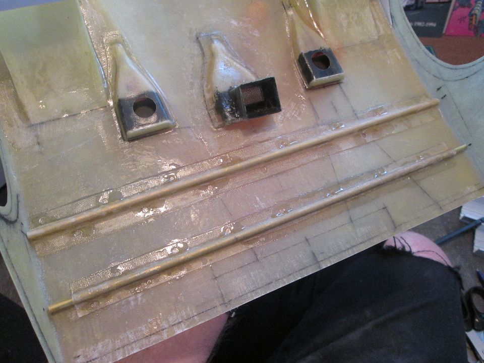 I'll put some fibreglass cloth over the whole lot eventually, but even like this they do a great job of reinforcing the tail. I'm not so much worried about the fibreglass being strong enough, but it's more about stopping it moving and twisting and this having an effect on any filler and paintwork. Next job was to add the recesses for the two tail-light units. Moulding these in-place was going to be a struggle, so I fabricated them in fibreglass sheet and styrene: 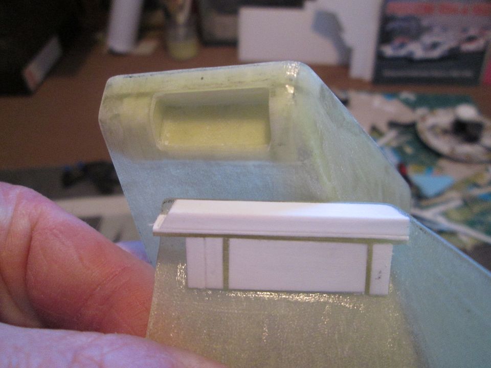 The end result is crisper and sharper than if they had been moulded, so I'm pleased. It also reinforces the tail a little bit, which doesn't hurt as I'll eventually be adding some wing supports. Before fitting these panels I had to notch the top edges to fit over the brass tube, and added some styrene angle to help with the gluing process. The other strip is to give the back edges wheel-arch panels something to rest against: 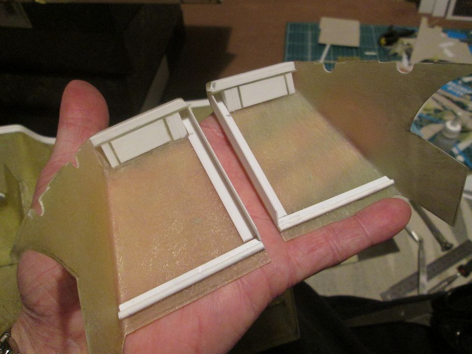 The end result:  The undertail sections have been CA'd in place, and the tail itself has been cut-back and filed to suit. A thin strip of fibreglass has been added to connect the two sides together (with some styrene reinforcement on the inside), and there will be more fibreglass added. I'm now working on creating the 'socket' where the tail support frame will locate, and deciding how to add the flat panel which continues the curve of the undertail. Lots to do, but the overall shape of the tail is now complete - I'm even planning to start making the wing support fins in the next few days. So, that's where I am now. I'm thinking ahead to what I want to be doing over the long Easter weekend (probably more fibreglassing and working on the tail section). There might be something else I can fit in as a 'just get it done this weekend' job, so we'll see what happens. I also have a little 1:43 project I need to spend some time on soon (spoiler - not a Porsche!) so I'll start a WIP thread for that when I'm ready to go... All the best, SB |
|
|
|
|
| The Following 2 Users Say Thank You to ScratchBuilt For This Useful Post: |
NickChan28298 (12-19-2022),
Petersm99 (04-28-2022)
|
|
 |
POST REPLY TO THIS THREAD |
 |
|
|


