|
|
|

|
|
| Search | Car Forums | Gallery | Articles | Helper | AF 350Z | IgorSushko.com | Corporate |
|
| Latest | 0 Rplys |
|
|||||||
| WIP - Motorsports Post topics for any "Work In Process" motorsports vehicles in this sub-forum. |
 |
 Show Printable Version | Show Printable Version |  Email this Page | Email this Page |  Subscribe to this Thread
|
|
|
Thread Tools |
 04-27-2021, 03:18 AM
|
#31 | |
|
AF Enthusiast

Join Date: Jun 2005
Location: Red Lake, Ontario
Posts: 2,519
Thanks: 3
Thanked 28 Times in 28 Posts

|
Re: Opel (Vauxall) Kadett V8 GTR 1:10 scratch build
This is incredible. The work is fascinating and it is fun to see a car being born right in front of our eyes. Keep up the great progress.
__________________
|
|

|

|
|
05-18-2021, 02:37 PM
|
#32 | |
|
AF Enthusiast
Join Date: Nov 2008
Location: Norwich
Posts: 649
Thanks: 21
Thanked 111 Times in 87 Posts
|
Re: Opel (Vauxall) Kadett V8 GTR 1:10 scratch build
Very, very nice! There's nothing to say that you can't use styrene to create shapes and forms that are irregular, or curved, but the trick is working out how you do it. You certainly seem to have this under control! Bravo, again.
SB |
|
|
|
|
|
05-31-2021, 10:10 AM
|
#33 | |
|
AF Newbie
Thread starter
Join Date: Oct 2020
Location: Netherlands
Posts: 57
Thanks: 7
Thanked 8 Times in 7 Posts
|
Re: Opel (Vauxall) Kadett V8 GTR 1:10 scratch build
Hi everyone,
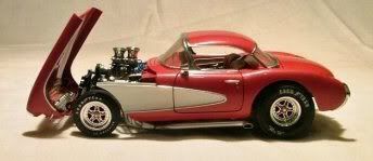
Time for an update. Continuing with the floor on the right side front. This part was modified by the Hovemann team to hold the Dry sump tank. This tank contains the oil which is pumped through the engine, the benefit of this system is a much smaller oil carter at the bottom of the engine so it can be placed lower for a better gravity point. Long story, pictures show everything, this is Dry-sump oil container place by the Hovemann team:  This tank was also placed as low as possible to get a low center of gravity... So they cut a hole in the floor, seen from the bottom:  To create this from styrene i glued two strips of 0,3mm styrene together making a cilinder. To close one end with a cap i cut out a circle and made a cut to the middle to fold the ends over each other and glue it. I trimmed a piece from the middle console to make it round so i could glue the cilinder in place. Then i finished the footplate to the right of the cilinder. Now i could trim the cilinder back with a Dremel to almost the correct height and angle. I used sanding paper and a file to shape the last part of the cilinder.    The floor place into the chassis looks like this:  As you can see i also installed the firewall. For that i even had to trim back the footplate from the driver side. The reason is they put the firewall more to the rear so it could connect to the front windscreen bottom, which is now from the Kadett and not from the Corvette anymore. On the next picture u can see the left trimmed footplate:  Last thing i did with the firewall was open up all the cable glands with a "punch and die" plier (very handy in these kind of situations).  The hole for the steering column is also made with a square piece of styrene with a small tube glued in place.  The rear part of the chassis is also covered with the original floor from the Corvette. It consists of two small "buckets" , maybe for two seats in the rear of the Corvette (I realy don't know), and behind that a flat floor.  From the left rear wheelcase it looks like this:  I started creating the "buckets" from 0,5mm thick styrene and connected them with a square rod on the right distance.   Also around the top of the bucket i glued square rods so could use them to glue the flat floor around it.      After that the flat floor part with the ribbing on top. The pieces on the side are covering the angled sections from the rear cross member.    And seen from the bottom of te chassis....  I also created a detailed beam on the middle partition section, this is also an original Corvette item but all the holes were done by the Hovemann team too save weight.  Last but not least i made a start with the front wheel suspension points. Below on the 1:1 picture u can see how it looks and even this is not original anymore, everything was remade to save weight for this car.  All parts made from different thickness styrene:       Thats it for now, thanx for all of your previous positive replys.
__________________
Thx for watching,  Greetz Peter Greetz Peter
Last edited by Midnight Creep; 05-31-2021 at 11:51 AM. |
|
|
|
|
|
06-01-2021, 03:23 AM
|
#34 | |
|
AF Newbie
Join Date: Feb 2009
Location: Uppsala
Posts: 24
Thanks: 12
Thanked 6 Times in 6 Posts
|
Re: Opel (Vauxall) Kadett V8 GTR 1:10 scratch build
Great job, this is so satisfying to follow!
|
|
|
|
|
|
06-02-2021, 02:24 PM
|
#35 | |
|
AF Regular

Join Date: Oct 2008
Location: Tilburg
Posts: 368
Thanks: 1
Thanked 13 Times in 13 Posts
|
Re: Opel (Vauxall) Kadett V8 GTR 1:10 scratch build
 |
|
|
|
|
|
01-28-2022, 02:27 PM
|
#36 | |
|
AF Newbie
Thread starter
Join Date: Oct 2020
Location: Netherlands
Posts: 57
Thanks: 7
Thanked 8 Times in 7 Posts
|
Re: Opel (Vauxall) Kadett V8 GTR 1:10 scratch build
Hi everyone,
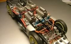
Since i finished my VW T1 in December last year i can spent now all my time on the Vauxall. Most of the time i invested in detailling the engine and things around the engine, like the bellhousing , gearbox and engine mounting. The last time i showed the engine it look like this on the next 2 pictures:   First i started with the engine covers, next picture shows an example of the real item:  I made the covers from several layers of styrene with different thickness:   On the upper two parts of 1 cover exactly on the edge are the mountings holes where the M6 bolts should come. To create that i made a template with all the holes drilled so i could copy it 4 times.  Now i could make all the holes a bit larger and cut the 4 pieces just on the edge of the holes. After sanding an angled edge they look like this:  Next picture shows them all 4 ready:  And test fitted on top of 1 cover:  After glueing them together everything was sanded. The cilinder heads also needed a lot of detailing, the next photo shows all exhaust outlet ports on the outside of the heads and other details like the oil fill point on the top of one.  With some pieces of tape the engine put together:   On the middle part top of the engine comes a starter engine, made from tube and discs of styrene:   The engine mounting construction is a self made piece from the Hovemann team. It replaced the heavy original contruction an made it a lot easier to disasamble the engine block from the car. 2 Photos below shows the construction, only parts not made on these 2 pictures are the uprights with the connection point to the engine, on photo no.3 u can see them.    And this is what i made from styrene tube and sheet, my construction also doesn't have the uprights because at this moment i don't know how high the engine will come:   Next 2 pictures how it will look when installed in the chassis:   The next i made is the bell housing, this is an original Corvette item butt i guess with another clutch and flywheel:   To create this shape i used the same technique i used for the tunnel inside the interior. First i cut two round pieces from styrene and glued them to each other with 3 small distance parts:   Now i wrapped it with 0.3 mm styrene sheet (the shape of the styrene was made by rolling the two discs over a sheet of paper and press the form into it)  After the glue was dry i noticed that the distance between the 2 discs was too much so i removed the small disc and cut a piece from the cilinder and glued a new disc on it. Because the real bellhousing isn't completely round i shaped it by glueing some extra pieces of styrene on cilinder and sanding it in the right shape. After that i glued the housing on a 0.3mm sheet which was cut to fit the back of the engine. The outside of the housing was detailed with strips styrene and a small tube like the original housing. At last the connection plate to the gearbox was glued on the housing.   The next item to make is the gearbox. It is a RD 906 speed shifter from which i could find some nice technical drawings, so all measurements were available:   The basic shape of the gearbox is a cilinder so thats were i started with. I used a pvc pipe with a diameter of 22,4 mm, i needed it to be 23 mm so i wrapped it wit a piece of 0.3 mm styrene:  From this tube i cut 3 rings with the same lenght:  Next i made are some discs from 0.7 and 2mm styrene, roughly cut wit a scissor, put them into a battery drill and used a file to made them nicely round.  The 0,7 mm discs will create the vertical lines on the gearbox. To make the horizontal lines i made a drawing onto paper.  I placed the drawing under a piece of glass and gleued (wood glue) the first ring onto the glass using a 0.3mm thick disc to create an open space between the ring and the glass. This is done so i would have some overlenght on the strips glued to the ring. After the ring is removed i can sand it down completely straight with the side of the ring.  On the picture below i started with glueing square 1mm profiles to the edge of the ring.  On the next photo the first ring is removed from the glass, on the right side u can see the 0.3mm overlenght.  Now the cilinder could be made by putting the rings and discs together.  My cilinder is still round but the real gearbox has flat parts on the outside. I used a small file to flatten the round shape between the horizontal strips:   Now i neede to make the front of the gearbox, again from several discs of styrene glued together. Then i used a small saw and file to give it the correct shape, from a 0.3 mm sheet i made the raised part on the front of the gearbox.  And this is the result:    On the end of the gearbox also a round "box" was needed, this will hold the axle to connect to the cardan shaft.   Picture below, the engine, bellhousing and gearbox put loosely together:  The inside of the cilinder heads also needed detailing by making the inlet ports. U could see them on one of the 1st pictures from this post. The shapes are like 2 small tubes wich are melted together in the middle. To create this i started by cutting small tubes with a tube cutter:   These tubes have a diameter of 4mm (0.5 mm wall thickness) , to "melt" 2 tubes together the overall width (2 tubes together) should be 6mm so from each tube 1mm from the side had to sanded of. To do so i put a 3mm drill inside the tube and sand it completely flat on one side, so 0.5 mm is romoved. Then i replaced the 3mm drill by a 2.5 mm drill and sanded it further down. After sanding them all they look like this:  Now i could glue them all together:  One side of all these tubes need an angled edge from 50 degrees to make the connection to the cilinder head. For that i bended a small piece of metal in the right angle, now i could align a file axactly along the metal so can sand the small tubes. Here u see the parts glued onto the cilinder heads:  The injection system which will be on top of the engine was also created from sheet and strip. Here's how the original look;   And this is how they became:    For illustration on top of the engine:   Also for detailing the front of the engine i made a start, not ready yet:   Then i made the engine mounts which will hold it in place. These mounts are the connection with the frame i showed earlier in this post. These are the parts from styrene:   And glueing them together and finishing it with som bolt heads:   And the place on the engine where it should be glued to:  Right now these are all the parts i made for this engine:  Last thing i want to show is the start of making the exhaust system. This engine has a four in one exhaust, 4 pipes coming from the engine along the underside going into 1 big pipe. The diameters from the exhaust pipes connected to the engine are roughly 40-45mm, underneath the engine they flow over to straight pipes with a diameter of 50mm and the four in one piece lets them all 4 go over into a pipe of 76 mm. On my 1:10 model the diameters will be 4-5 and 8 mm.  The straight pipes are easy to make but the 4 in 1 pipe is another story. Even the real 1:1 product is tough to make, especially the welding is very difficult becaus it has to be completely gas proof. This is an open model of a 4 in 1 coupler:  My first attempt to cut the tubes wasn't working , there had to be another way to cut them.  So i did some research and they should look like this:   When glued together it looks like this:   To cut the overlenght i first glued a small disc on the end to make it stronger:  Now i could saw of the overlength and sanded it a bit:   To gain a good strong connection between the 4 straight pipes and the 4 in 1 section i glued some small pieces of pipe into the straight ones:  And this is how it now looks:   This it where it ends for now, see u in the next update.
__________________
Thx for watching, Greetz Peter
|
|
|
|
|
|
01-29-2022, 02:06 AM
|
#37 | |
|
AF Newbie
Join Date: Jan 2008
Location: Nivnice
Posts: 98
Thanks: 2
Thanked 14 Times in 14 Posts
|
Re: Opel (Vauxall) Kadett V8 GTR 1:10 scratch build
Very inspiring!
|
|
|
|
|
|
01-29-2022, 02:50 AM
|
#38 | |
|
AF Regular

Join Date: Jun 2005
Location: london
Posts: 414
Thanks: 3
Thanked 22 Times in 20 Posts
|
Re: Opel (Vauxall) Kadett V8 GTR 1:10 scratch build
Great work , keep photos coming
|
|
|
|
|
|
02-21-2022, 10:41 AM
|
#39 | |
|
AF Newbie
Thread starter
Join Date: Oct 2020
Location: Netherlands
Posts: 57
Thanks: 7
Thanked 8 Times in 7 Posts
|
Re: Opel (Vauxall) Kadett V8 GTR 1:10 scratch build
Hello everyone.
Time for the next update. Im trying to get the chassis as ready as possible, so everything that's directly mounted onto or in the chassis because later on when other parts are added i probably cannot do it anymore. One of those directly mounted objects are the air-jacks, a pressure system to jack up the car. This car has 3 air-jacks, 2 at the front and 1 at the rear. On the next photo you see the jack mounted on the rear, its right in the middle of the cross member (there's a small red package mounted to it with straps, that's a tow cable):  On the next photo you can see the 2 jacks at the front of the car, they are mounted directly through the chassis:  In the chassis at the front i drilled two holes and glued in both of them a styreen tube.   The jack is also made from a styrene tube, i made a thread on it with a tool. This tube fits exactly into the tube mounted in the chassis.  I also made a ring nut which is used to clamp the airjack to the chassis.   I made the system working by using another small tube, which slides into the tube with the thread, and glued a small piece of tube and a small disc to the bottom.  In the rear cross member i also drilled a hole.....  The next parts from styrene will be glued on the bottom of the cross member:  Like the front i also made it working by adding another tube inside and a foot to rest on. It looks like this on the next photo, on the second picture you can see how it works:   After the works on the jacks i glued the whole interior into the chassis:    On the inside of the chassis i added some reinforcements like the real car also has:   All the red dots u see are the mounting points for the rollcage. I also made a start on creating the rollcage. The tube diameters for these tubes are in the guidlines from the FIA. For each different race class there are different rules. For hillclimb cars the main rollcage has to be 50 mm diameter and the secondary tubes in between are 40 or 45 mm in diameter. For my model i chose 5mm for the main tubes and 4mm for the secondary tubes, the difference in thickness is now clear to see. The next problem already occurs, because "cold" bending tubes results in kink and when the tube is bended by adding heat the tube will disform. During my study as electrician in the 80's and 90's i learned to bend pvc pipes with a bending spring. By inserting this spring into the tube, the tube contains his shape while it is bend. I wanted to try the same principle for bending the tubes for my rollcage. The tubes i use for my car are 5 and 4mm in diameter and the inner diameters are 3 and 2 mm. There are no such small bending springs but i used braided metal wire with a diameter of 2 and 3 mm. They fit exactly into the tubes:   To make the bends in the styrene tube you will have to start from the middle if there are more than 2 bends. If you start on the outside you can't get the metal wire out of the tube or not in again. To make sure the metal wire goes in far enough i put a small piece of tape on the wire bebore i insert it into the tube.  When 1 bend is ready i pull the wire back for the next bend. To make all the bends a good drawing is important.   The overlenghts are cut with a small pipe cutter:  Test fit onto the chassis:  I also made the 2 tubes which are on the left and right side of the chassis:  Next time more from the rollcage beacause it is pretty complex. Back to the engine parts i made the alternator. The alternator is on top of the engine so it will be visible from all sides. It's a nice looking unit with a lot of vent sleeves so i did my best to make a nice copy in scale 1:10. I started with a sketch from the side and the front:  And a simple drawing on scale:  I used that drawing to make the first parts from styrene sheet:   The air vents are made from small pieces of 0,3mm styrene......    And after a few hours of crafting it looked like this, almost finished:    Only on the outside it needed some styrene staff.... and its finished:   Last part of this update is the second exhaust which is almost finished, they both still need some sanding and filling too smoothen everything.  Thx for watching,
__________________
Thx for watching, Greetz Peter
Last edited by Midnight Creep; 02-21-2022 at 11:21 AM. |
|
|
|
|
|
02-21-2022, 02:05 PM
|
#40 | |
|
AF Enthusiast
Join Date: Nov 2008
Location: Norwich
Posts: 649
Thanks: 21
Thanked 111 Times in 87 Posts
|
Re: Opel (Vauxall) Kadett V8 GTR 1:10 scratch build
Hi Peter,
Wow - where to start? The chassis just looks better and better with each new detail you're adding. The roll-cage bends are great - what tube are you using for these? The wall-thickness looks bigger than the Evergreen tube I mainly use - which is why I make my bends in sections! I tried bending with a little heat on my original 917 models years ago and didn't get any results, but the thicker tube combined with the wire core seems to work. The alternator is another lovely little assembly, but with a lot going on. I see your sketches and I can understand how you're looking at the real thing and working how to create it. Same for the engine parts in the previous update - excellent! All the best, SB |
|
|
|
|
| The Following User Says Thank You to ScratchBuilt For This Useful Post: |
Midnight Creep (02-21-2022)
|
|
02-21-2022, 02:45 PM
|
#41 | |
|
AF Newbie
Thread starter
Join Date: Oct 2020
Location: Netherlands
Posts: 57
Thanks: 7
Thanked 8 Times in 7 Posts
|
Re: Opel (Vauxall) Kadett V8 GTR 1:10 scratch build
Thx SB,
I can get different wall thickness tube online and in stores here in the Netherlands. The tube i'm using has a wall thickness of 1mm (5mm out and 3mm in) . I can get them also with a thickness of 0,5mm but to my opinion the more outside material the better they wil bend simply because there is more material to stretch. And about the drawings, I make them all the time when to create more difficult parts or sections. It makes it easier for me to figure how to build the parts. I like to draw but i guess U already saw that.
__________________
Thx for watching, Greetz Peter
|
|
|
|
|
|
03-19-2022, 10:01 PM
|
#42 | |
|
AF Enthusiast
Join Date: Jun 2005
Location: Red Lake, Ontario
Posts: 2,519
Thanks: 3
Thanked 28 Times in 28 Posts
|
Re: Opel (Vauxall) Kadett V8 GTR 1:10 scratch build
Incredible. I can't wait to see these works of art get painted.
__________________
|
|
|
|
|
|
04-19-2022, 12:58 PM
|
#43 | |
|
AF Newbie
Thread starter
Join Date: Oct 2020
Location: Netherlands
Posts: 57
Thanks: 7
Thanked 8 Times in 7 Posts
|
Re: Opel (Vauxall) Kadett V8 GTR 1:10 scratch build
Hi everyone.
Almost 2 months ago i posted my last update. The build not going very fast so i'm collecting update photos till i have enough to show some progress. I'm gonna continue with the rollcage, all tubes are measured on the car because it was impossible to make any kind of drawing. For that i glued the first parts which are connected to the chassis with white glue so it woulkd be easy to remove the whole cage after it was finished. All tubes added are 4 or 5 mm thick and to make all the ends fit onto other tubes i used sandpaper wrapped around 3 or 4mm aluminum tubes. Now the most important te photos:         On the next picture u will see a tube that is also part of the rollcage, the bend is not in the middle and at first i did not know what the purpose of this tube was. On my ref pics it aklso din't show what it was used for until i was looking at some pictures from the bottom of the car. I found out there is a safety bracket installed around the drifeshaft to prefent it from breaking through the bottom of the car. That safety bracket is connected to the lowest part of the tube inside the car, probably because its a very strong connection.  Then added som emore tubes at the back of the chassis:    To close all the small gaps in between all the tube connections i made liquid styrene and used an injection syringe (without needle) to put it into the gaps.  For that i had to remopve the whole cage from the chassis so i could reach all gaps that needed some filling.       It looks a bit messy but i still need to sand all connections. What im very happy with is the strong connection the liquid styrene gives to the roll cage. To put the focus on something else i made a start with the front brake discs. None of my ref pics gave me a good shoot on how they exactly look but luckily i also have all the car info. The info : 15" front brake disc from Wilwood , 6 caliper also wilwood. So it was quit easy to get som pictures from the wilwood site, looking like this:   And also a nice drawing:  I started with 1mm thick styrene and cut out 4 circles. I'm using a circle cutter for that:  If u are going to use it i have 2 tips: 1: don't use the sharp end of the blade , if u can turn the blade around (it that is possible, see the picture: The sharp blade won't stay in the same groove all the time u go round, so u will not end with a nice round circle.  Tip no 2: if u are going to turn the cutter do it the other way around so the blade is gonna "scribe" through the styrene. And because it is scribing its removing surface material each time u go round. For a 1 mm thick plate u will have to go round quit a lot, i did it from both sides using the same centre hole drilled with a 0,5mm drill. The circles i cut are 36mm in diameter, i drew a 30 degree pattern on it and drilled 0,5mm holes in the spots where i want to make a bigger hole.  The bigger holes (4mm) are made with a punch plier with center point.  I only needed to make 4mm holes in two discs but i was a bit to fast with it so all discs have holes in them (not a problem because i need to cut a large hole in 2 dics so they will dissapear)  These Wilwood discs are grooved with a-symmetrical grooves, i made them with a broken 0,5mm drill (scribed them in).   The inner shape of the discs are a ring so i had to cut the whole middle section:   The outer disc has half rounds in the middle part, so this cut will be in the middle of all the 4mm rounds that i cut.  Everything was sanded afterwards, now it was time to make the air vents in beteen the 2 discs. I made 8mm long sticks from 1mm square tubes. They all need to be glued under an angle onto the first disc, for that i made a small styrene tool which was pinned into the middle of the disc with a 0,5mm drill.  After putting them all around it looked like this:  Now the second disc was glued on to of it:  After cutting all the excessive lenghts te discs look like this:   Now the middle part of the disc needs to be scratched, i found a good drawing from that part also:  I started the same way wit 2 discs from 1m thick styrene with a 30 degree pattern on it, holes drilled on the edge of the disc.  And used the punch plier to make 4mm holes:  And cut with the circle cutter:  This disc has to be 3mm thick so i cut 2 more discs from 2mm thick styrene: This disc needs an angled edge so for that i drilled a 0,8mm hole in the middle so it would fit onto my dremel tool:  I put the tool into a battery drill, and used a sharp knife to make the edge angled, don't try to cut the styrene but put the knife into a 90 degree angle onto the edge of the styrene.  Before and after:   Both done:  I glued the two 1mm discs onto the 2mm discs:  After the glue had dried i used a dremel tool and sandingpaper on a alu tube to cut the holes also in the angled part of the 2mm disc.  The result looks like this (just put on to each other) maybe not competely done yet, depends on how i'm gonna to make the wheel fixation.   Thats it for now , more in the next update (engine parts etc etc)
__________________
Thx for watching, Greetz Peter
|
|
|
|
|
|
06-14-2022, 12:22 PM
|
#44 | |
|
AF Newbie
Thread starter
Join Date: Oct 2020
Location: Netherlands
Posts: 57
Thanks: 7
Thanked 8 Times in 7 Posts
|
Re: Opel (Vauxall) Kadett V8 GTR 1:10 scratch build
Hello everyone,
Time for the next update. I finished the last time with the front brace discs, this time i made the rear ones. They are different from the front because the rear brake discs are drilled versions. Heres the example:  Like the front discs i started cutting some circles with my cutter, 5 to be exactly and now youre wondering why 5 , well i'm using one as a master to drill all the holes at the same position.  I drilled one quarter of the disc and also made a slot in it to make the carvs in de discs.  Each time turn the disc 90 degrees and this is the result:  Now i started to cut out the middle part of the discs, and glued the vent bars on to the discs.  Left and right discs are the opposite from each other:  The rear discs have a cylindrical part in the middle, i made it from 0,3mm styrene warpped 2 times around a cilindrycal shape with the right diameter.  This part was cut in two pieces and a lid was glued on top. The middle of the discs were modified with a file to make some gaps wich will be next to the cilinder.  Then the parts were glued together:  It still needs some finishing touch with sandpaper but the main part is okay now. The next part on my list is the rear differential and the mounting of it. This is a Chevrolet part called Dana 44, there are several different versions from this differential used for several brands of vehicles. The mounting is also colled a "batwing", the picture below speaks for it self: (actual picture from a corvette)  And picture below shows a open version from the same part.  Since there a different versions and looks from this part i used some pictures from another car to be the example for my build because the pictures from the car im building arent good enough. First i started making a drawing in scale 1:10  I used this drawing to make the grouond plate which is the connection between the mounting bracket and the diff.  The "batwing" is made out of 0.75 mm thick styrene. I copied the drawing on the styrene and firtly drilled the corners of the holes wich need to be removed.  I copied these holes on to another piece of styrene to get 2 similar parts.  By adding small strips to the front and the rear i made the construction.  As u can see i also added some parts onto the plate .  The rounds at the ends of the wing are round pieces cut with my plier out of 2mm styrene plate and glued together to the disired thickness.  All parts glued together under a small angle looks like this.  For the differential i started making some basic shapes:       And then i skipped som pictures because the next one already shows some more detail, but i think the idea is clear.  Like Scratchbuild i also started using "greenstuff", very handy indeed to make shapes and close gaps. Next picture just for the look with the "batwing" next to the diff.  Now it was only a matter of detailling the diff and the wing to get a good copy of the real one:        Then i only have one item left and that are the inlets from the engine. These are difficult to make from styrene especially because i need to make 8 of them and they need the exact same shape because they are on top of the engine and very visible. After thinking it over several weeks/moths i found a nice solution. I'm using plugs which i use for my work with the exact diameter.  After putting them in a drill and give it a reshape with a sharp blade it looks like this.  And after cutting them to the correct lenght i put them on top of the engine, the front one is not having the right shape so that was going into the bin. The other ones still need to made:   Thats it for this time, i hope u like it.
__________________
Thx for watching, Greetz Peter
|
|
|
|
|
|
06-16-2022, 06:28 AM
|
#45 | |
|
AF Regular
Join Date: Oct 2011
Location: Kilmarnock, Scotland
Posts: 306
Thanks: 6
Thanked 37 Times in 35 Posts
|
Re: Opel (Vauxall) Kadett V8 GTR 1:10 scratch build
Insane scratch building. Clearly there is no limit as to what you can replicate.
Fantastic skills. It will be a great model. How much styrene do you go through? |
|
|
|
|
|
|
POST REPLY TO THIS THREAD |
 |
|
|

