|
|
|

|
|
| Search | Car Forums | Gallery | Articles | Helper | AF 350Z | IgorSushko.com | Corporate |
|
| Latest | 0 Rplys |
 04-19-2022, 11:21 AM
|
#121 | |
|
AF Newbie
Join Date: Oct 2020
Location: Netherlands
Posts: 57
Thanks: 7
Thanked 8 Times in 7 Posts
|
Re: 1/8 Porsche 956
Nice update SB.
The shape is now really showing, looking good. How are u gonna paint the bodys parts, will those all be seperate parts because when i look at the tail section is that a multi parts section or just one when its finished?
__________________
Thx for watching,  Greetz Peter Greetz Peter
|
|

|

|
|
05-03-2022, 03:20 PM
|
#122 | |
|
AF Enthusiast
Thread starter
Join Date: Nov 2008
Location: Norwich
Posts: 649
Thanks: 21
Thanked 111 Times in 87 Posts
|
Re: 1/8 Porsche 956
Hello again,
Plenty of photos in this update - I didn't realise it was a month since last time. Peter: my plan for painting the bodywork (and everything else) is to leave as much as I can in separate pieces, and see what happens. I'll airbrush as much as I can, particularly where 'smooth' surfaces are required, but I'm sure a lot of the smaller details and mechanicals will be painted with a regular brush (as on the 935-78). The main tail section will be a mix of the liveried outer surfaces, and some plain 'composite' on the underside, but it should be possible to mask as required and airbrush it all. I have yet to decide which livery I will use for this project, as - so far - I haven't been building a specific car. I suspect it will come down to which sponsorship logos and lettering I can scale-up from 1/24 kits and print onto decal paper! I've spent the last few weeks continuing to work on the tail end of the car. Most of the work has involved creating the extension of the undertail to enclose the gearbox. It was never going to be possible to include this piece in the main underbody mould (made in May / June 2020) as there were too many unknowns at that point. Now, with the main tail fitted in place and the gearbox in position, I could start planning the undertail - first, in cardboard: 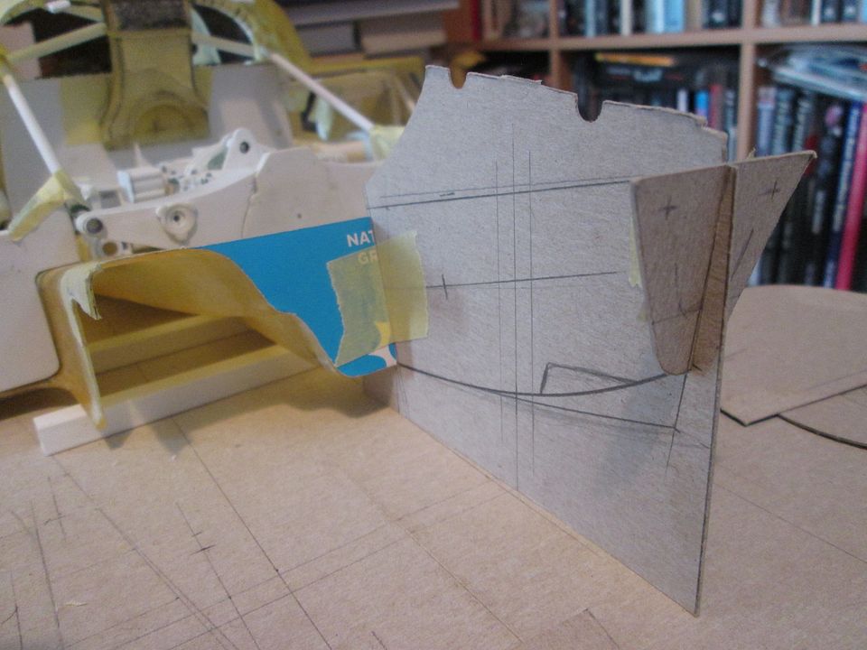 ...and from there I could rough-cut a foam block and start shaping: 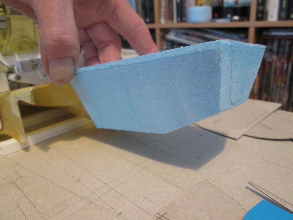 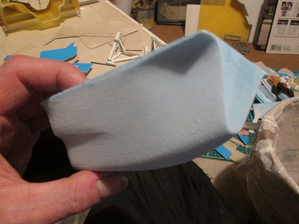 After several layers of fibreglass and some trimming: 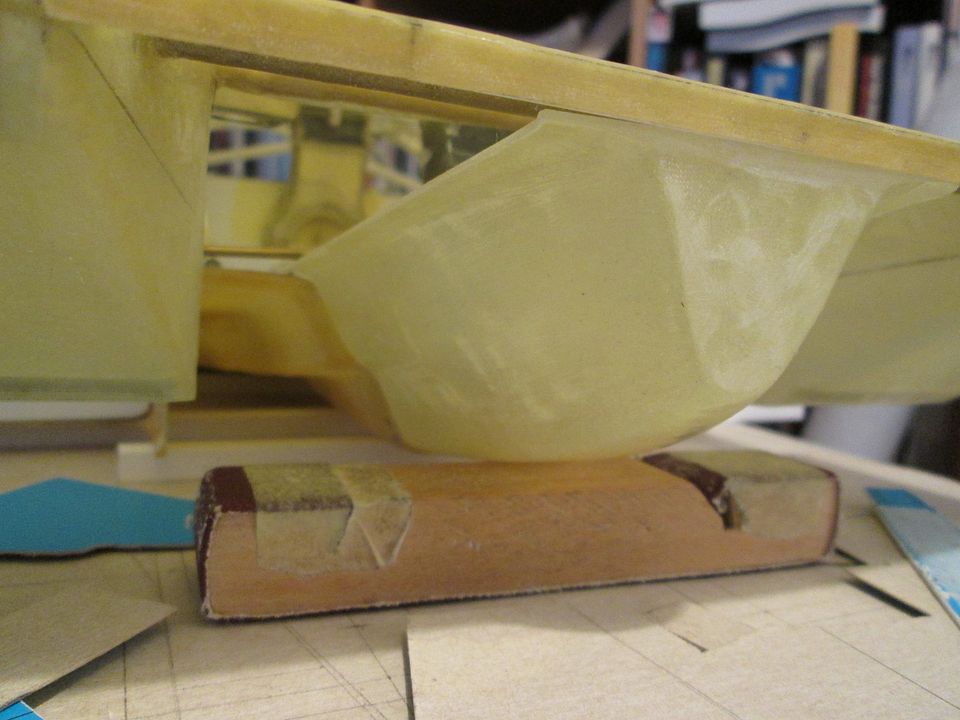 Despite my best efforts, it wasn't possible to exactly match up the shape of the back end of the existing undertray with the front edge of the new undertail. My first thought was 'it'll be fine, it's hidden away underneath and no-one will notice'...but when you just know that something isn't quite as it should be...so I had to do something about it. These next two photos jump ahead by a week or so, but show what I did. Having trimmed the two mating edges to butt against each other I added a styrene mounting flange around the new undertail section. This allowed me to drill and pin through in three places, for a solid connection. Next, I applied Greenstuff to the outside to build up the four corners where there was a mismatch: 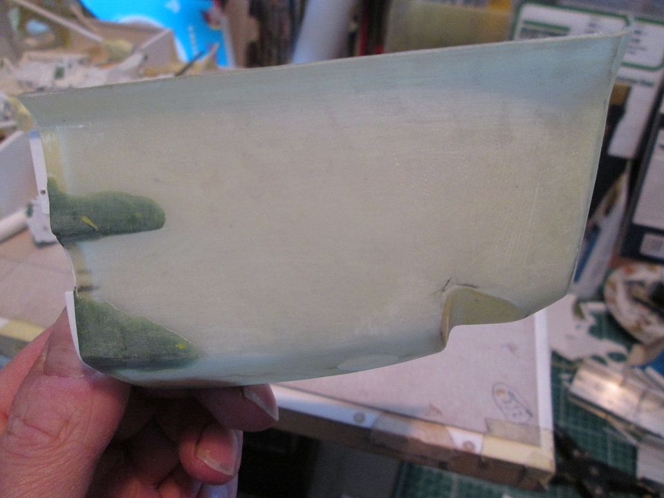 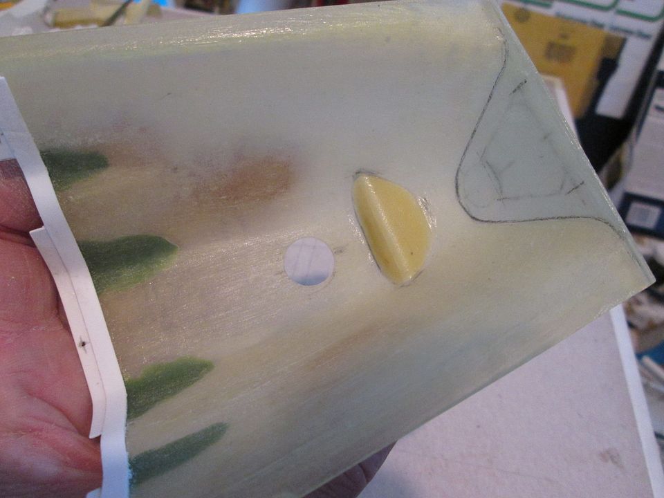 In these photos you can also see where I've added the hole for the rear airjack, and the notch on the underside which makes space for the towing eye. Again, the notch could have been incorporated into the main mould, but it would have been a brave move! I felt it would be safer to add the notch afterwards, when I could confirm the position of the airjack. Rather than simply cutting the hole then grafting in two flat plates, I wanted something with a small radius between the two to make it look 'moulded'. I used an off-cut from one of the main cockpit sill panels, fitted it in place, added plenty of CA glue on the inside, then filed the outside edges back to meet the undertail. I'm very pleased with the result. The airjack itself is one of those pieces that I've probably (no, certainly) made more complicated than it needs to be...but it might pay off in the future. My main concern was the strength and durability of the towing eye itself, particularly with the potential for it getting hit repeatedly when fitting the undertail, and other knocks and scrapes. I cut this piece from flat fibreglass (approx 0.75mm thick) rather than styrene to improve it's chances, but I also had the brainwave of making the bottom end of the airjack removable (and therefore replaceable in the event of towing eye damage). What made it time-consuming was working out how to sleeve both sections together, allowing the towing eye to protrude into the inside, and also including two magnets to click both parts together! The next photo doesn't really do it justice, but it'll give you an idea: 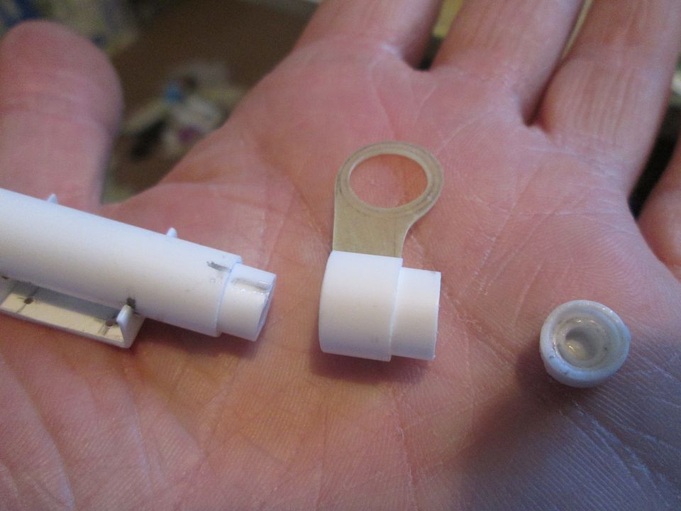 In this shot you can see that I've added some bolt detailing where the towing eye clamps around the airjack body, and how it fits through the slot in the underbody notch: 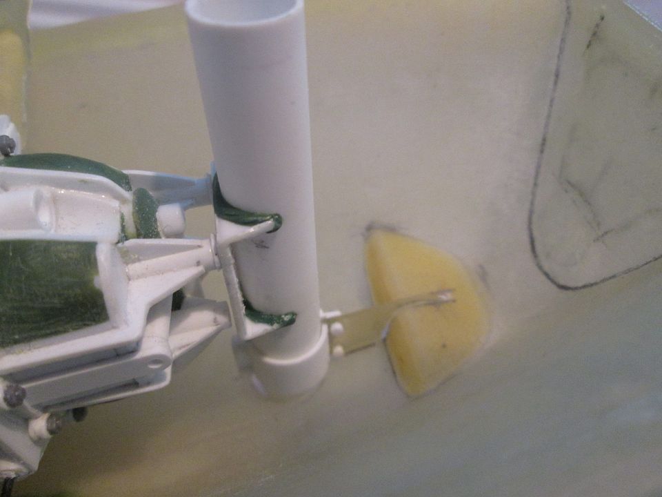 I've just got to finish off the detailing of the top capping and the air-line plumbing, then the airjack is basically finished. Next up, it's back to the main tail section. In between most of the above I've been doing small jobs on this - the wheelarch inner panels have been bonded into place, I've added fibreglass reinforcement where the various pieces fit together, and the styrene around the back edge gives me a mounting 'socket' for the where the tail support frame will eventually fit: 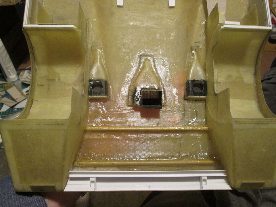 There's still more to do here, but it's making progress. Finally for tonight, I made a start on making the main rear wing parts. I'm making the 'short-tail' high-downforce version of the 956, so the wing support plates are quite impressive-looking:  I cut the two plates from 1/8" balsa wood, rounded the top edges and added a slight taper to the trailing edge, then applied three layers of light fibreglass. I did quite a lot of smoothing and rubbing-down between layers as I wanted to minimise any ridges or high-spots, and keep the edges 'sharp'. For now I've simply drilled and pinned two holes in the underside of each plate to locate them, but I'll eventually glue them in place and reinforce with fibreglass and resin: 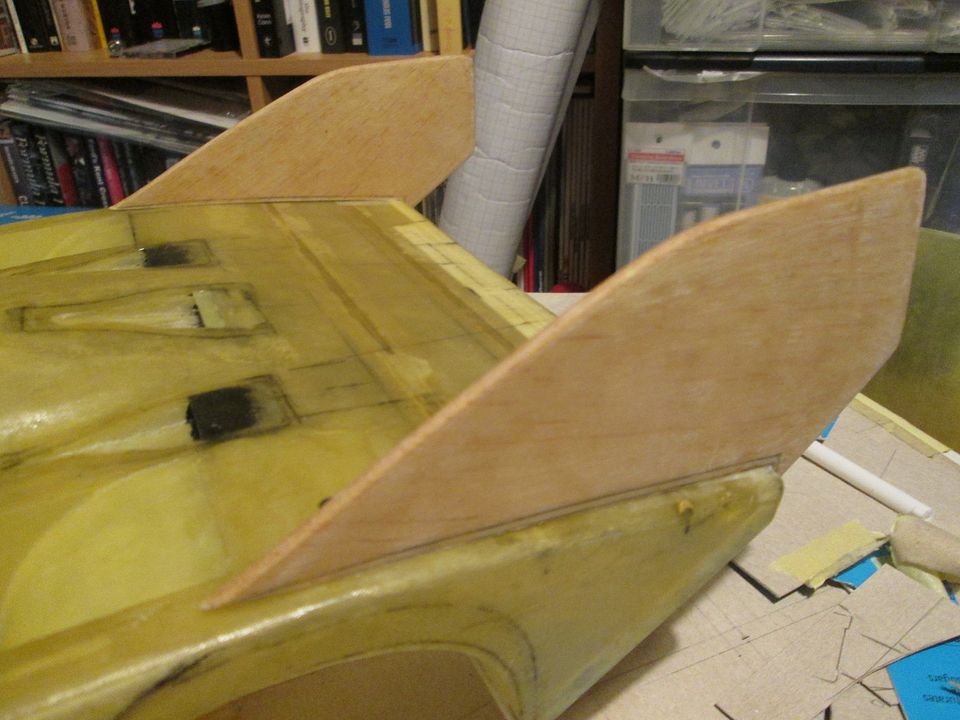 Annoyingly, I didn't take any photos of the main wing plane while I was cutting it to shape - too busy with the hot-wire and making a lot of dust! Anyway, I created the shape I wanted, laid-up three layers of fibreglass (again, lots of rubbing-down between layers) and cut it to length: 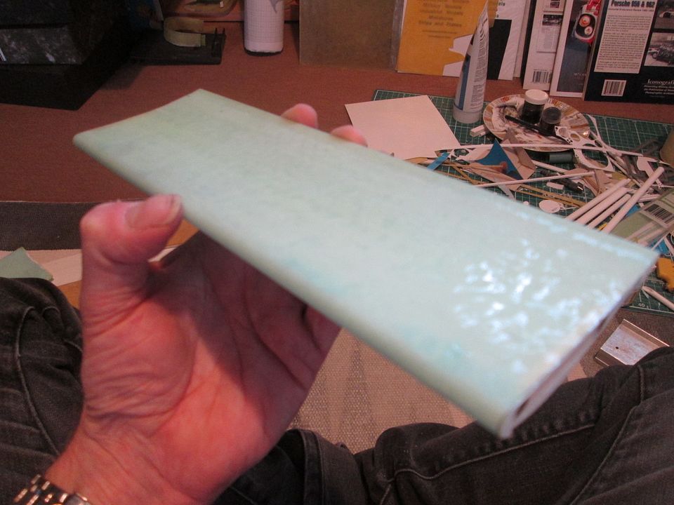 The basic foam wing shape was quite 'flexible', but the fibreglass did a great job of stiffening it up - "not a surprise" says everyone who's ever built a model glider or R/C aeroplane, I guess! My next step was to work out how the wing would be fitted into place between the endplates. Normally I'd be trying to pin through into the actual adjuster brackets on the wing, but for the 956 I wanted to do something different. Magnets again! As the wing isn't particularly heavy I don't feel that it needs a 'solid' fixing, so if I include a couple of pairs of magnets at each end I should be able to drop it into place without having to pin or glue anything. That's the plan, anyway! In this final photo, these are the two adjuster plates I've made to fit onto each end of the wing: 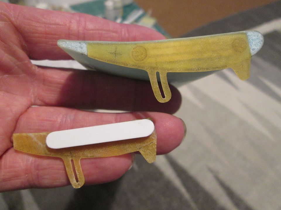 The styrene pieces hold the two magnets, and I've cut a pair of matching sockets into the ends of the wing so they fit flush. I'll add some fixing details to the two tabs hanging down below, but they won't need to be functional. I can paint the mainplane separately to the adjuster plates, then glue them in with UHU 'foam-friendly' glue. All I have to do now is to place the wing in position, work out where the outer magnets have to be, then to drill the main endplates to suit. Sounds easy enough, but I'm sure it won't be a five-minute job...! That's it for tonight. Have a good week, everyone, and hopefully it won't be another month to next time (yeah, yeah, I know - I've said that before!). SB |
|
|
|
|
|
06-05-2022, 03:46 PM
|
#123 | |
|
AF Enthusiast
Thread starter
Join Date: Nov 2008
Location: Norwich
Posts: 649
Thanks: 21
Thanked 111 Times in 87 Posts
|
Re: 1/8 Porsche 956
Hello again,
Bit of a mixture tonight - mainly to get up-to-date before heading off to Le Mans next week! So, following on from last time, I drilled four sockets into the main wing end plates to take four 5mm magnets: 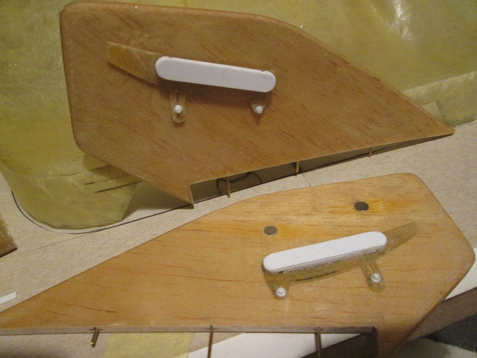 I also added the detailing for the pivot fixings (not functional) and slimmed-down the shape of the curved adjuster sections. I'll paint these parts separately to the wing mainplane before gluing it all together later. I still have to make the support struts, but that's a job for another time. Next, I returned to the panelling under the tail section. I'd roughed-out most of this in cardboard a while ago, but wanted to finalise things before fitting the wing endplates. After confirming the angles, etc, I added some support angles to the wheelarch panels, and the vertical plates which close-off the upper part of the gearbox: 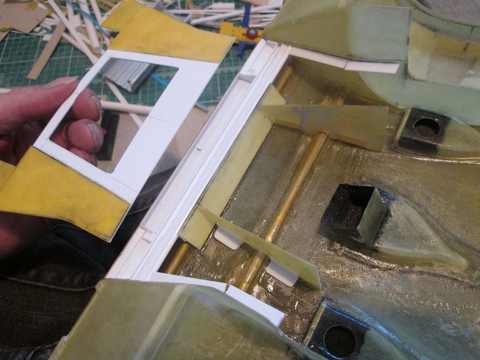 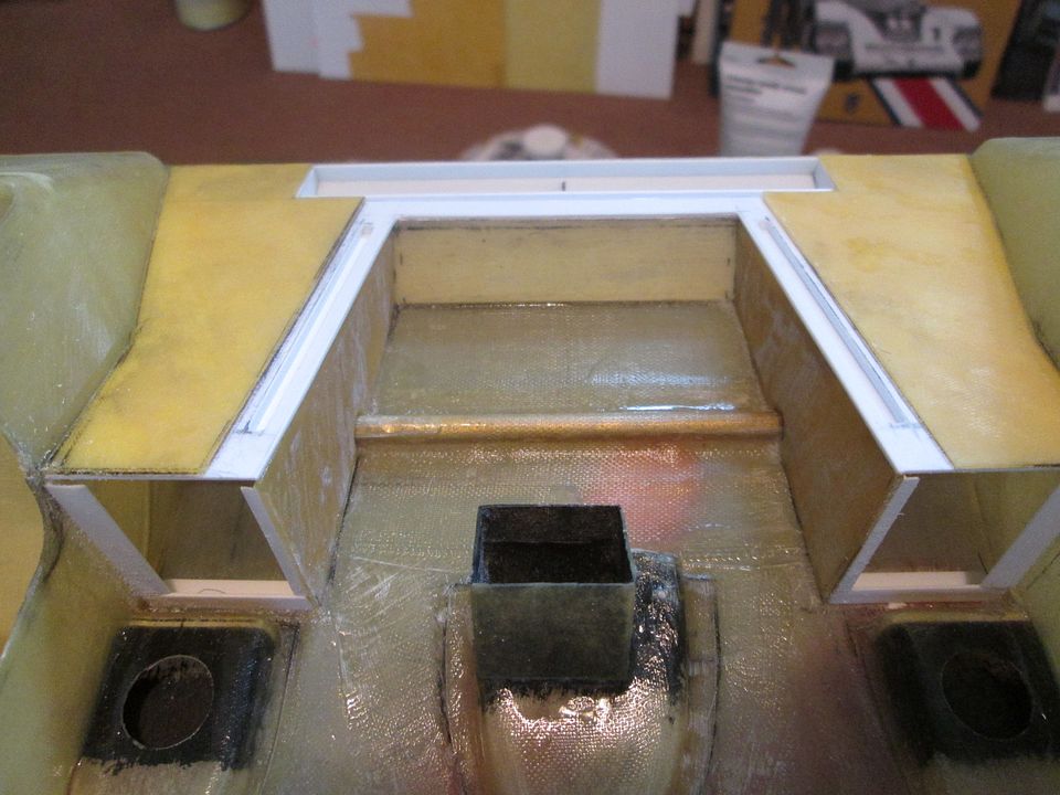 ...and the whole lot fits together with the gearbox section: 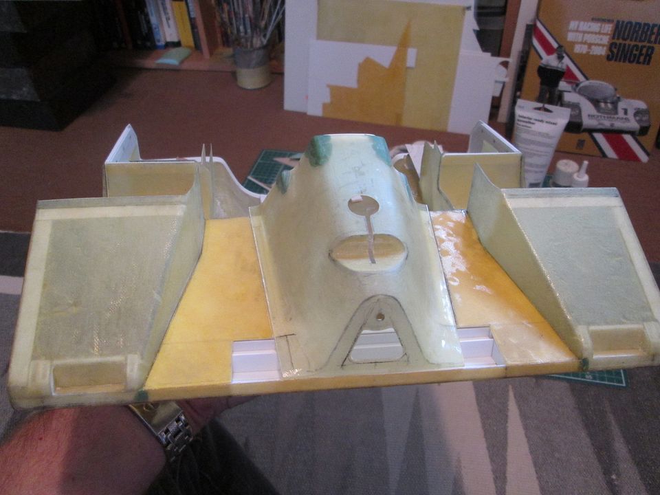 The two square gaps either side of the gearbox cover will eventually be filled by the underside of the tail support beam. Although I've made a start on mocking this up I can't really take it to completion until the gearbox is fixed in position. By this stage I realised I'd spent a lot of time working on the back end of the car, so it was time for a change. I wanted to get the fit of the nosecone tied-down a bit more, and as part of this I had to extend the rear edges a little in order to re-shape the fit to the windscreen surround. Fortunately, I still had some pieces of off-cut fibreglass available from when I had made the original parts, so I could recycle a couple of thin slivers and CA them in place. The fit to the leading edge of the windscreen surround was a trickier prospect - I'd already extended the rear edge of the nose once with more fibreglass, and didn't want to do that again. Taking some inspiration from Midnight Creep I hit on the idea of building up the edge with styrene, then filing it back to shape. Simple! Except I'm trying to extend a curving edge at an angle, from a width of about 3mm tapering away to nothing. The solution was to add a length of 2mm styrene angle around the edge to form a foundation, then add a few layers of 0.4mm strip as bulk, then to file it to shape. Here's the finished result: 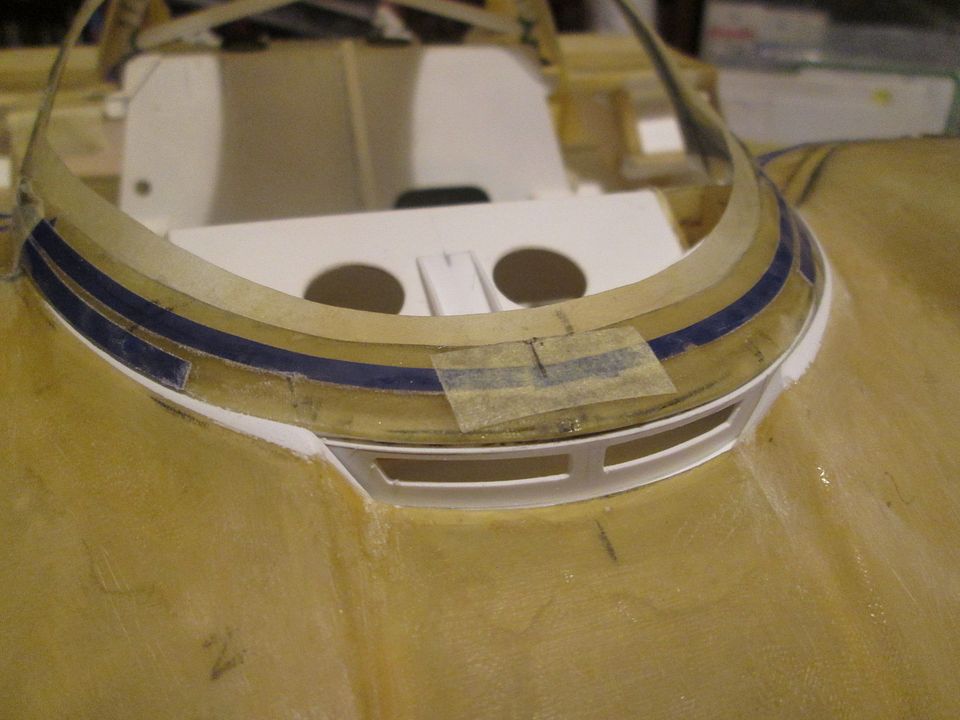 ...and from below: 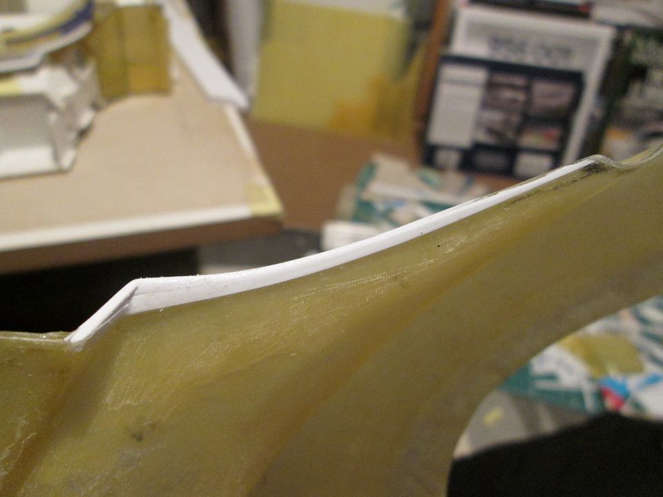 Next, the nose support frame. I wanted to make this using 3mm aluminium tube rather than styrene, for strength, but this would make some of the construction a little more of a challenge. So, the starting point was four legs pinned into a cross-bar, with mounting holes drilled into the pedalbox bulkhead and two sockets glued to the floor: 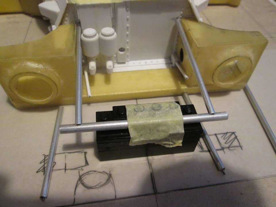 A diagonal tube was added for reinforcement, and to provide a mounting for the windscreen washer bottle and pump (made this weekend). The tabs extending forwards are made from fibreglass, with plenty of CA glue run into the joints and some Greenstuff for some heavy-duty weld detailing: 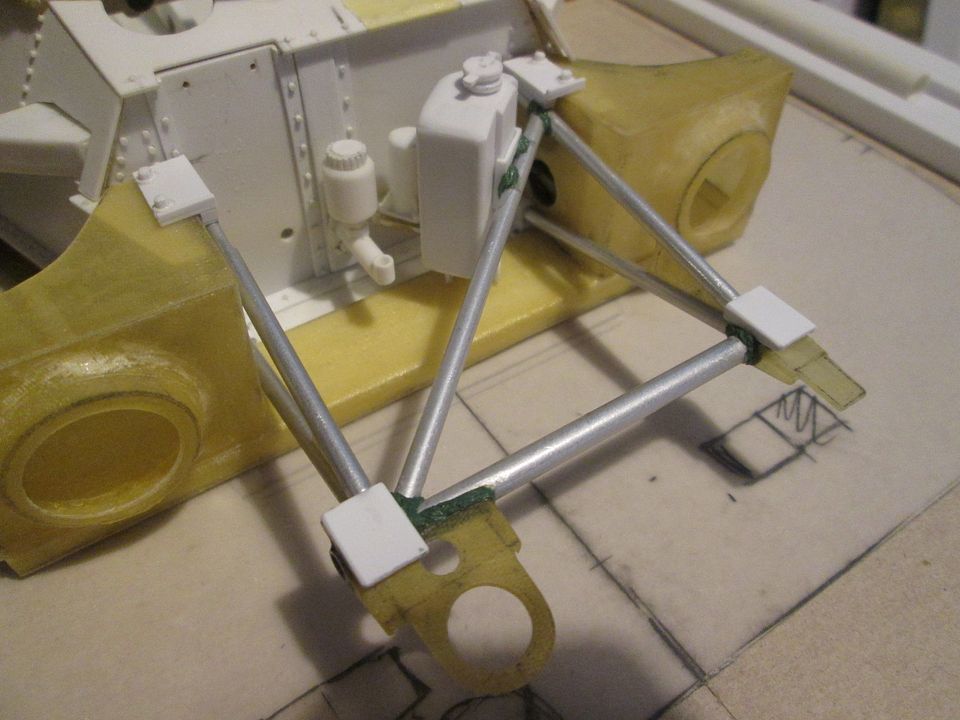 The towing eye fits through a slotted recess; I moulded this as a separate piece a while ago, and added it to the nose section last weekend. Rather than mould the two rectangular body-pin recesses in fibreglass (tried it, too small to get a good result!) I've made a single styrene section which will be glued in place: 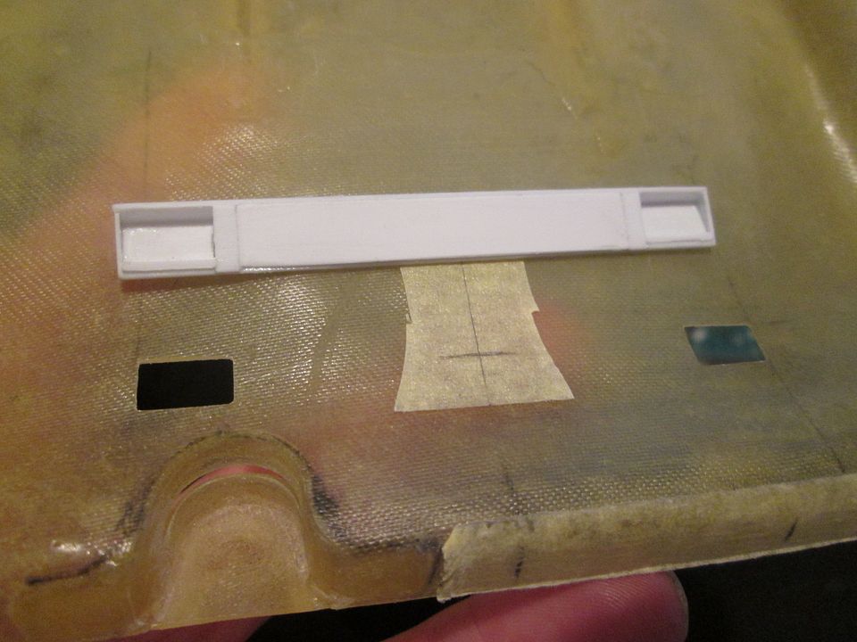 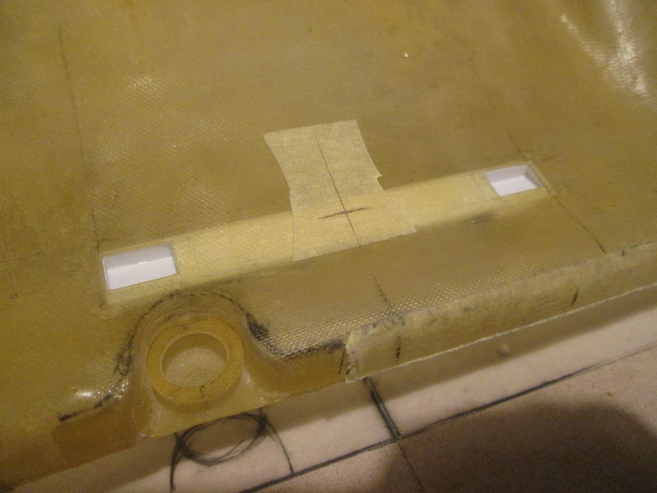 There's still more to do in this area - pods for the headlights, the brake cooling duct inlets, and fitting the floor panel. When more of this is in place I'll add some extra fibreglass to tie it all together. Last up for tonight, here's a couple of extra bits I made recently - the oil catch bottle and bracket, and the tail light: 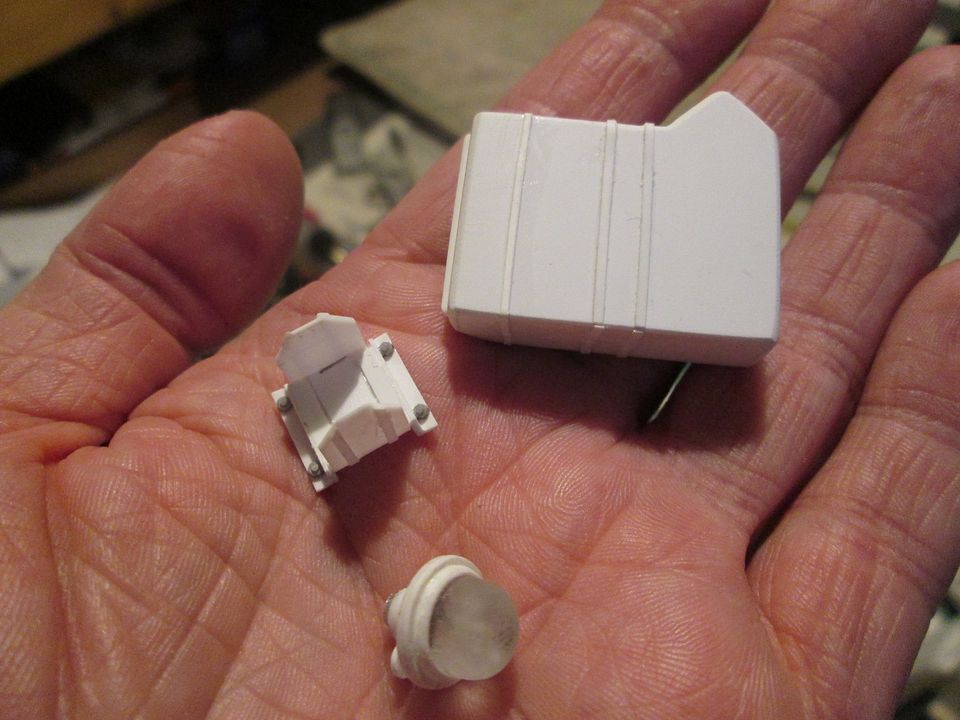 ...and that's everything up-to-date. Hopefully the next post will include some interesting machinery on display at LM (no Group C support race this year, but as it's the 40th anniversary I'm optimistic of something in the paddock village somewhere...)! Have a good week, SB |
|
|
|
|
|
07-19-2022, 03:43 PM
|
#124 | |
|
AF Enthusiast
Thread starter
Join Date: Nov 2008
Location: Norwich
Posts: 649
Thanks: 21
Thanked 111 Times in 87 Posts
|
Re: 1/8 Porsche 956
Hello again.
It's too hot to do any meaningful modelling tonight, so it's time for an update! It was so good to be back at Le Mans last month, but I was a little surprised that the anniversary of Group C wasn't noted - other than an '88 TWR XJR-9 on display at Jaguar's stand, I didn't see anything 'appropriate'. Maybe they had something in the museum, but I was half-expecting to find a display in the paddock village somewhere. Perhaps they were saving themselves for the LM Classic... So, back to the 956. Continuing to add details to the nose section, I started making the S-shaped ducts for the front brakes. I cut two foam blocks to match the shape of the underside of the body, then started trimming them: 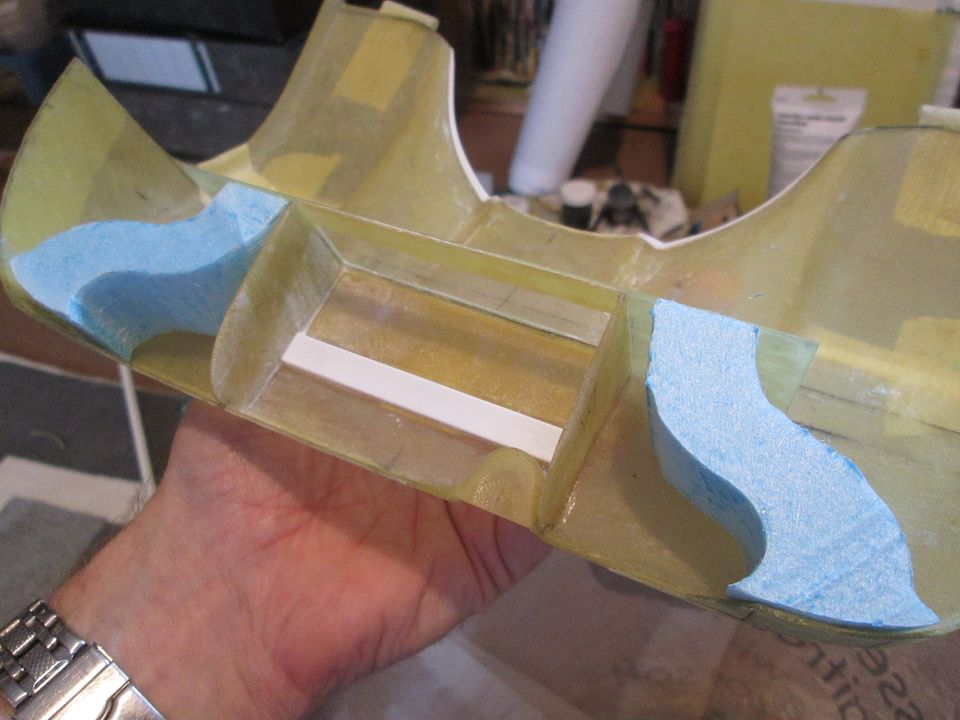 I didn't like the thought of trying to lay-up fibreglass over a four-sided solid (potentially very messy!), so I cut each pattern through the middle so that I could lay-up in two halves: 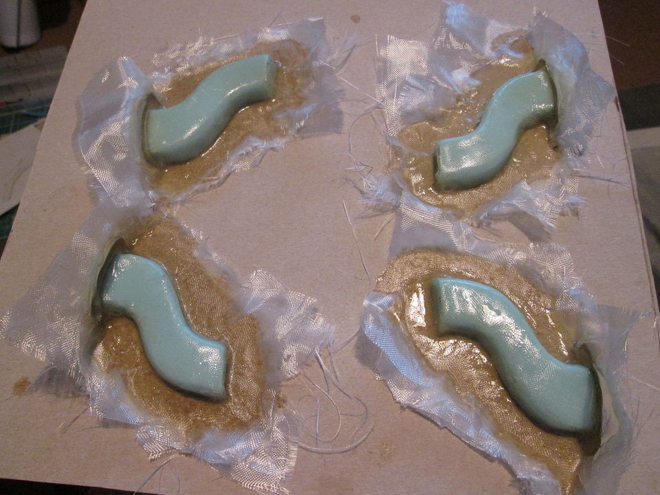 I ended up having to destroy the foam patterns to remove the fibreglass, but after gluing them back together they were fitted into place in the nose, and reinforced with more fibreglass: 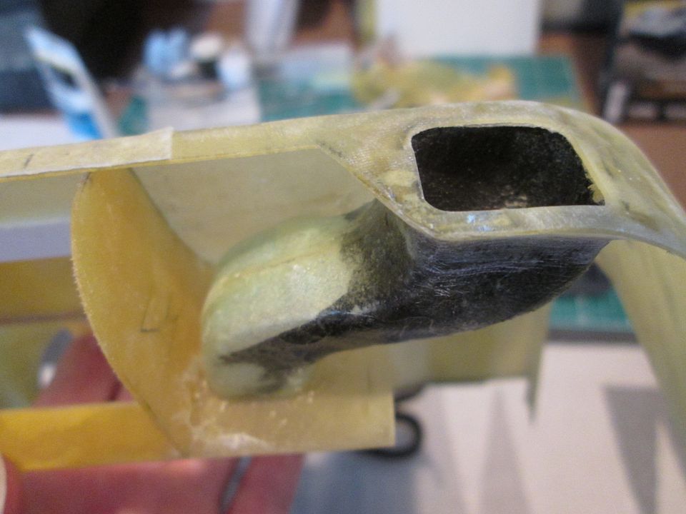 The duct opening in the front has been cut to approximate size, and will be fettled once I've added some filler or Greenstuff around the inside. The other end of the S-bend is currently blank, but will have a short length of tube glued into place to mate-up with the matching ducts on the front of the chassis. After messing around with these ducts for a while, I wanted a change of scene - time to make some driveshafts! I've been thinking about these for a while: the main question was how to make some realistic-looking 'rubber bellows' for the CV boots in styrene, while still allowing some articulation of the shaft. Once again, the solution was more magnets. I started the CV boots with a series of doughnuts cut from styrene tube, in three sizes. With thin spacers fitted in between, this gave me the basic shape: 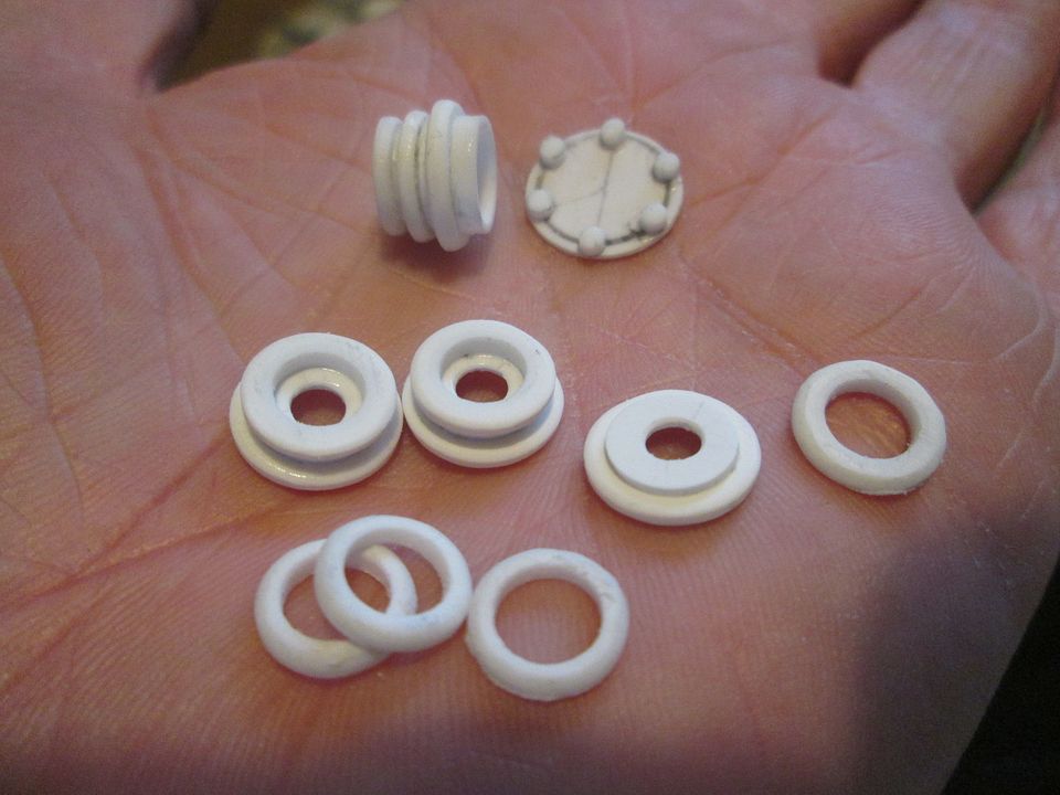 The idea of using magnets came to me while driving home from work one night - why not fit a magnet into the end of the drivehaft, then use a ballbearing from a paint mixing pot to allow it to flex? There was no need to magnetise both ends - mainly because I didn't have the exact length yet, and also because a single magnet on the gearbox end would keep the shaft in place during assembly, while allowing me to slide the shaft into place through the upright from the outside. Here's the detail: 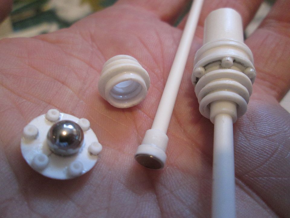 The ballbearing sits in a hole cut in the CV boot flange and is then trapped by a similar hole inside the boot itself, allowing enough of the ball to protrude and make contact with the end of the shaft. When the car is at ride-height the shafts should be pretty much horizontal, but there's enough articulation on these to allow a bit of mis-alignment. I'm very happy with them! 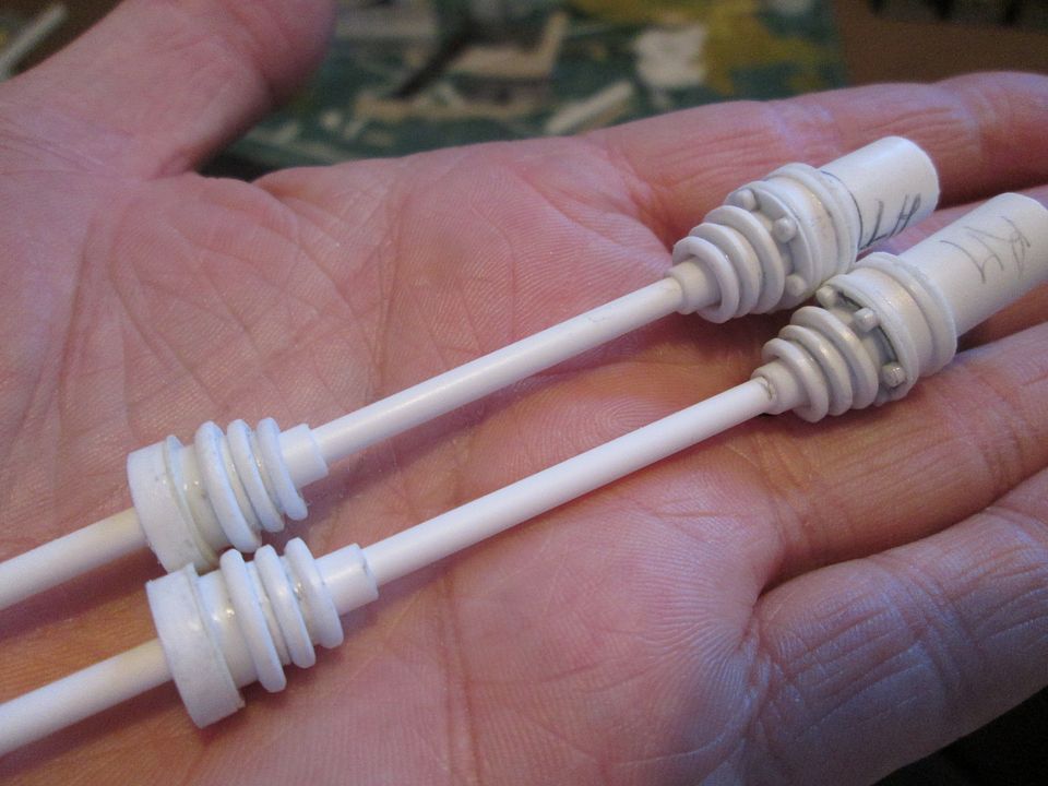 Now for something different - how do I make the headlight covers? On the 935-78 I was able to use thin clear sheet slid into place, but this was not an option for the 956 - they're curved in several directions. I stumbled across some resin-casting videos online, and that sparked the idea - I've been using it for long enough to make the fibreglass parts, why not use it for moulding too? I set about making some test-pieces - first job was to make a couple of quick fibreglass panels from the nose. I used one layer of the lightest cloth, then two layers of a thicker 3mm multi-directional cloth: 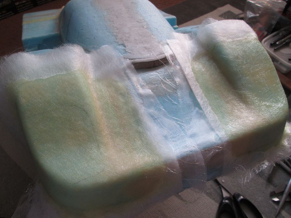 I quickly added some cardboard strips to give the mould some depth, a smear of vaseline as a release agent, then started mixing up some of my normal epoxy resin. I had to do three pours to get everything covered, but it worked: 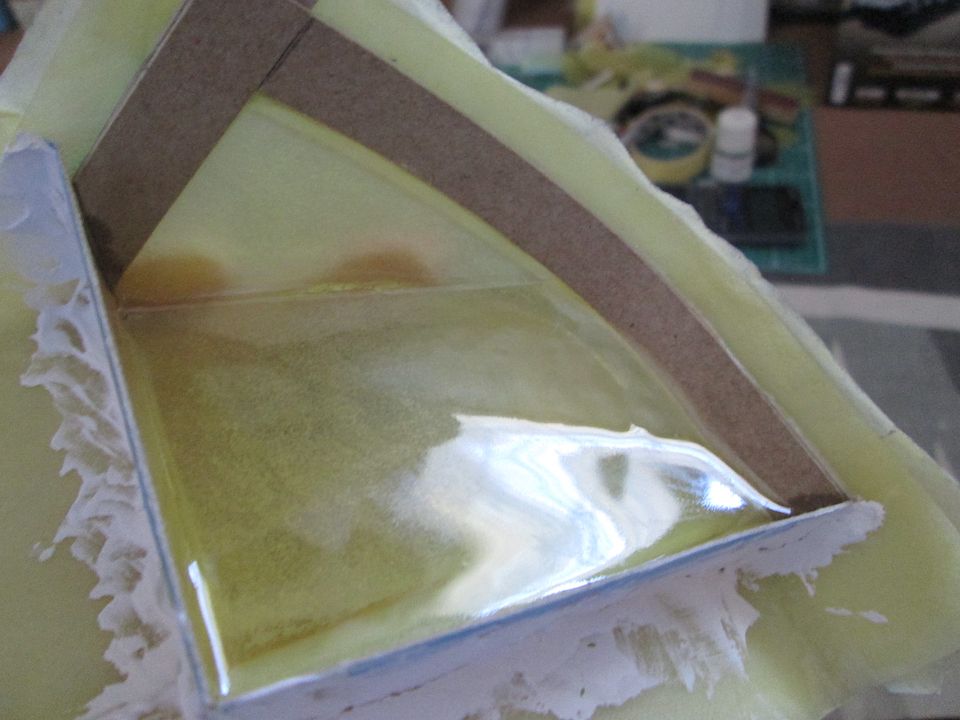 After removing it from the mould, the next test was to see how it responded to sanding, etc - could I get it back to a smooth clear finish? From this: 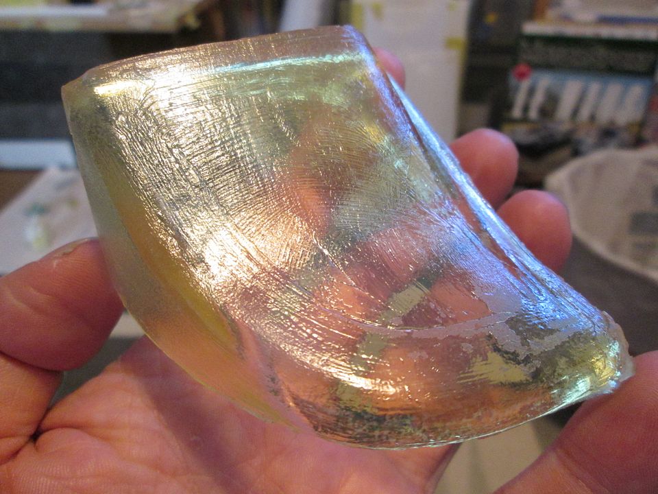 ...to this: 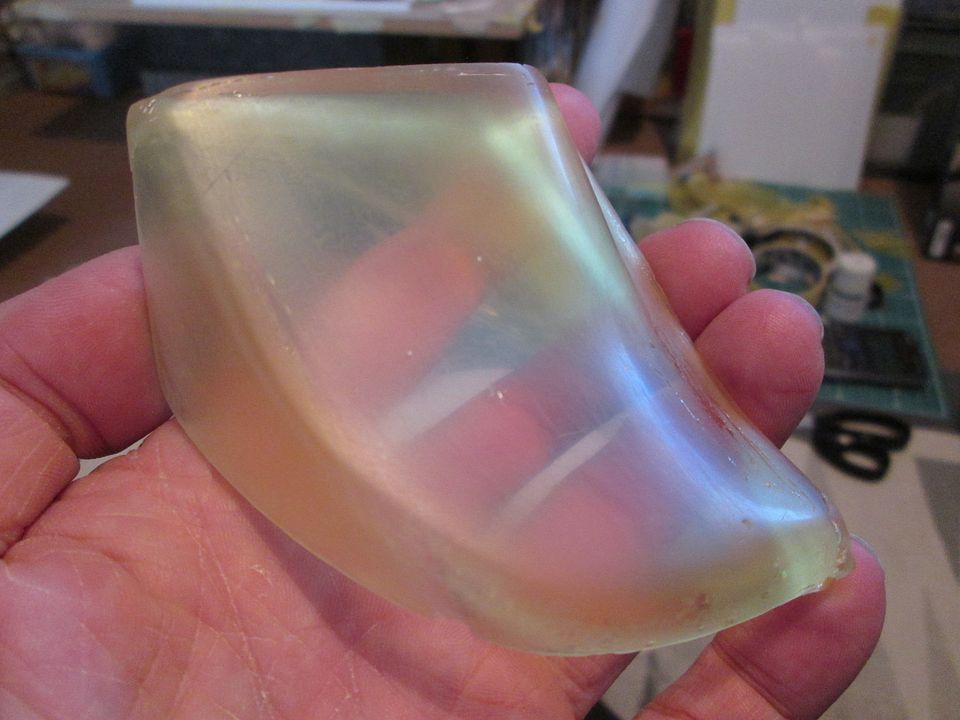 I started with some emery cloth, then worked through three grades of wet'n'dry, then used some of my micromesh cloth. I didn't use any proper cutting compound or polish, but I did try using a little toothpaste as an experiment. I think with more time, some compound, and some proper polishing afterwards, I'll be able to get a clear enough part. Now it's a case of doing it all again. but with refinements! I've bought some GlassCast clear resin, so that's the yellow tint taken care of. I've also re-made the fibreglass moulds so they're slightly larger (by about 0.75mm) - the finished shape needs to match the fibreglass shell I've already made, whereas the test version was the same shape as the mould. The test pieces ended up being quite thick in places, so that's something to tackle too. Hopefully I'll be able to make some more progress with these later this week, weather permitting. As always, thanks for having a look. All the best, SB |
|
|
|
|
| The Following 2 Users Say Thank You to ScratchBuilt For This Useful Post: |
NickChan28298 (07-31-2022)
|
|
08-30-2022, 03:48 PM
|
#125 | |
|
AF Enthusiast
Thread starter
Join Date: Nov 2008
Location: Norwich
Posts: 649
Thanks: 21
Thanked 111 Times in 87 Posts
|
Re: 1/8 Porsche 956
Hello again!
Although the very warm weather we've had in the UK this summer has made me put a few jobs on-hold for a while, I've still been making good progress. First-up, I poured a second version of the headlight covers using the clear 'GlassCast' resin: .JPG?width=960&height=720&fit=bounds) I re-made the fibreglass moulds to include the extra thickness of the bodywork, so the moulded shape will (hopefully) be the correct size. I had to make each part using multiple pours, positioning the mould each time to make sure the resin flowed where I needed it to be. This may cause me issues later on, but I can't see a simple way of being able to do a one-shot pour. We'll see. I haven't done any work on these other than getting them out of the mould, but I've got some cutters, polishers, compound, etc, and I can have another test-run on the original piece before going ahead: .JPG?width=960&height=720&fit=bounds) Next job was to get the fibreglass seat shell looking more like a proper seat. Overall, the method was similar to the 935: cover a series of pieces of thick styrene with material to make the padded spine of the seat, then cover the sides. One of my old work-shirts provided the material - a suitable dark grey, with the weave giving a nice textured look. It was critical not to have any glue seeping through the cloth, so most of the work was done with double-side tape: .JPG?width=960&height=720&fit=bounds) .JPG?width=960&height=720&fit=bounds) Slightly out of focus, but you get the idea: .JPG?width=960&height=720&fit=bounds) The styrene mechanism for adjusting the seat position is visible in the slot at the front - this will eventually be fixed to the floor of the tub on assembly. I've bent a length of ali tube which will fit into the two supports at the back of the cockpit - this will be glued to the back of the seat shell, reinforced with some fibreglass (either CA'd in place, or maybe resin), and then the shell will be painted. Making the seatbelts is a job for another time... Most of the work in the last couple of weeks has been focussed on the exhaust and turbo system. Some of these parts have been made for a while, but it was time to start pulling things together and maybe making the exhaust primary pipes too. First task - make the two 'collector' sections which will feed the three primaries each side into the first stage of the turbo assembly: .JPG?width=960&height=720&fit=bounds) As always there's a little bit of 'massaging' of the pipe sizes to suit the styrene sizes available, but at this scale it's not really a problem if the pipe is 0.1 or 0.2mm out! As long as it all fits together, and I can make the parts strong enough, I'm happy. After the collectors, I moved on to the two waste-gates. As with the 935, these branch off the main exhaust pipes; it's effectively the same combination of parts, but they're just mounted on the car at the sides rather than being hung off the back. The main bodies of the waste-gates are heavily-ribbed, so I made these from multiple layers of styrene sheet, using different thickness' to create the ribs, mounting flanges, etc: .JPG?width=960&height=720&fit=bounds) To make life a little easier, I decided to add a front support for the turbo assembly. It's not 'correct' to real life, but it'll stop things moving around during construction, and it'll hardly be visible once everything is in place: .JPG?width=960&height=720&fit=bounds) Here's how it all starts to look: .JPG?width=960&height=720&fit=bounds) Throughout this process there's a lot of thought being put into how this will all be fitted together once it's painted. Getting the mounting bolt detailing to line-up correctly between certain sections is much easier to do at this stage, for example, by separating the mounting bolt flanges from the main turbo bodies. On final assembly the main sections can be slid together, rotated into the correct alignment, and will be held in place by the connections to the intercoolers above, or the exhaust primary pipes below. That's the plan, anyway! Here's the two assemblies side-by side: .JPG?width=960&height=720&fit=bounds) ...and a detail of one of them: .JPG?width=960&height=720&fit=bounds) I've done all sorts of work on these over the last few days. The shape of the main mounting plates has been refined, I've added lots of hex-nut details, the tailpipes have been trimmed closer to the final length, I've added the little reinforcing tabs between the mounting flanges and the tailpipes...and greenstuff everywhere. The teardrop-shaped holes in the body panels have been cut and opened-out to suit the twin tailpipes each side, too. I've still got to do some final adjustment on the wastegate tailpipes, then either start gluing some of these sections together, or add some pins somehow to lock the alignment during the later stages of construction. I doubt whether these bits will be fully airbrushed at the painting stage, so it shouldn't be a problem to glue them together...providing this doesn't cause a fitment issue, or prevent access to something else. As usual, that's something I'll think about for a while before taking action! That's me up to date for now. The next job will be to fix the collector sections in place, then start creating the primary pipes to snake under the engine and line-up with the exhaust ports. Easy! Or, probably not. Once I have the exhaust system under control it'll be time to start thinking about autumn / winter jobs. I wasn't planning to do any airbrushing this year and there isn't really anything major that needs to be made in fibreglass at this stage, so I don't have any time deadlines to get those jobs done before it starts getting too cold outside. There's plenty of small detail jobs that still need to done on the engine, the front anti-roll bar needs to be made, the suspension needs to be finalised (front and rear), seatbelts, the fire system needs finishing, lots of pipe fittings need to be made, the dashboard and instruments, windscreen wiper...it's a long list. Worryingly, at the end of this year it'll be four years since this project started. It certainly doesn't seem like four years, but as the last couple of years have been a bit crazy for everyone, that might explain it! I think it's progressing well - the 935-78 was about 30 months from when I first sprayed the frame, fixed it to the floor panel, through to completion. I'm sure at some point in mid-2023 I'll reach the point where I have to get some paint on the tub and start fitting things together! All the best, SB |
|
|
|
|
|
09-01-2022, 09:19 AM
|
#126 | |
|
AF Newbie
Join Date: Oct 2020
Location: Netherlands
Posts: 57
Thanks: 7
Thanked 8 Times in 7 Posts
|
Re: 1/8 Porsche 956
Nice work on the waste-gates and the turbo's SB.
When i look at the size of the seat , it is so much bigger than the 1:10 scale i have to make same for the clear lenses, what size are the lenses originally, i guess over 50 cm wide?? Keep up the good work , some of it is so recognizable for me 
__________________
Thx for watching, Greetz Peter
|
|
|
|
|
|
09-01-2022, 01:18 PM
|
#127 | |
|
AF Enthusiast
Thread starter
Join Date: Nov 2008
Location: Norwich
Posts: 649
Thanks: 21
Thanked 111 Times in 87 Posts
|
Re: 1/8 Porsche 956
Hello Peter,
The headlight covers are currently about 60mm x 60mm x 30mm. The vertical edge is about 2.5mm to 3mm thick, and the main part is between 2mm and about 5mm thick. On one of them in the second photo you can just see a line marking the shape I'll be trimming them to. I'm hoping I'll be able to take a lot of the thickness out of them, while still being able to clean them up to a good finish. They're not going to be 0.5mm all over, but as I'm not able to vacuum-mould parts I don't have many (any?) alternatives. I can practice on the Mk1 version first before working with the clear ones! If this plan doesn't work, I will certainly try to mould them again - but instead of pouring the resin and allowing it to settle, I will try moving the mould until the resin sets. This might allow me to get a thinner section. Another option might be to try laying-up a couple of pieces of the lightest fibreglass cloth using the clear casting resin rather than the regular laminating resin. The cloth might be enough to stabilise the resin, and could absorb enough to become virtually transparent. Okay, so maybe I do have a couple of alternatives! I'll return to the headlight covers once I've made some more progress with the exhaust, and we'll see what happens. SB |
|
|
|
|
|
09-01-2022, 05:02 PM
|
#128 | |
|
AF Newbie
Join Date: Oct 2020
Location: Netherlands
Posts: 57
Thanks: 7
Thanked 8 Times in 7 Posts
|
Re: 1/8 Porsche 956
Difficult situation with the headlight covers.
Maybe i can give u another idea. Right now you are pouring the resin inside the mould. Why not make a positive mould and pour the resin on the outside. This way the "to much resin" will flow away and you will get a thin surface. Maybe its worth trying.
__________________
Thx for watching, Greetz Peter
|
|
|
|
|
|
10-10-2022, 03:12 PM
|
#129 | |
|
AF Enthusiast
Thread starter
Join Date: Nov 2008
Location: Norwich
Posts: 649
Thanks: 21
Thanked 111 Times in 87 Posts
|
Re: 1/8 Porsche 956
Time to get up-to-date again!
With the turbo and wastegate assemblies in good shape, I wanted to get the six exhaust primary pipes underway. My first attempt was unsuccessful - with the engine in place it was impossible to juggle the bits of wire that I was bending to create the core of each pipe. So, plan B: remove the engine. I measured and marked the position of the exhaust ports on the underfloor, so I now had six targets to aim for, and no engine to get in the way. With the two collectors in position either side, it was relatively simple to bend the core wires, then start adding the sections of styrene tube to build-up the pipes: 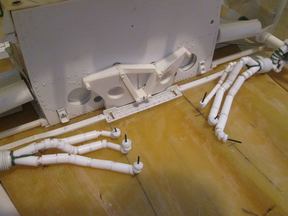 They need to be refined slightly, and the gaps need to be filled once everything is glued together, but the hard work is done. I just have to work out the final assembly sequence as it will be impossible to fit the pipes into the sockets in the engine once the underfloor is fitted... 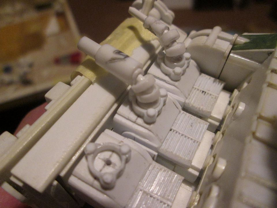 With the pipe positions sorted out, the next job was to cut the slots in the floor panel. These were used on the 956 to vent the cooling air drawn in through the fan and over the engine, out into the ground-effect tunnels. I guess the overall idea was to increase the airflow through the venturis, similar to a F1-style 'blown floor', but in practice it possibly wasn't as successful as Porsche hoped. From various accounts in books, it seems that many teams blanked off the vents for a performance gain in qualifying, but the resulting increased temperatures made it hard to maintain this trick over long periods. I've put them in, even though you'll hardly see them once the model is assembled: 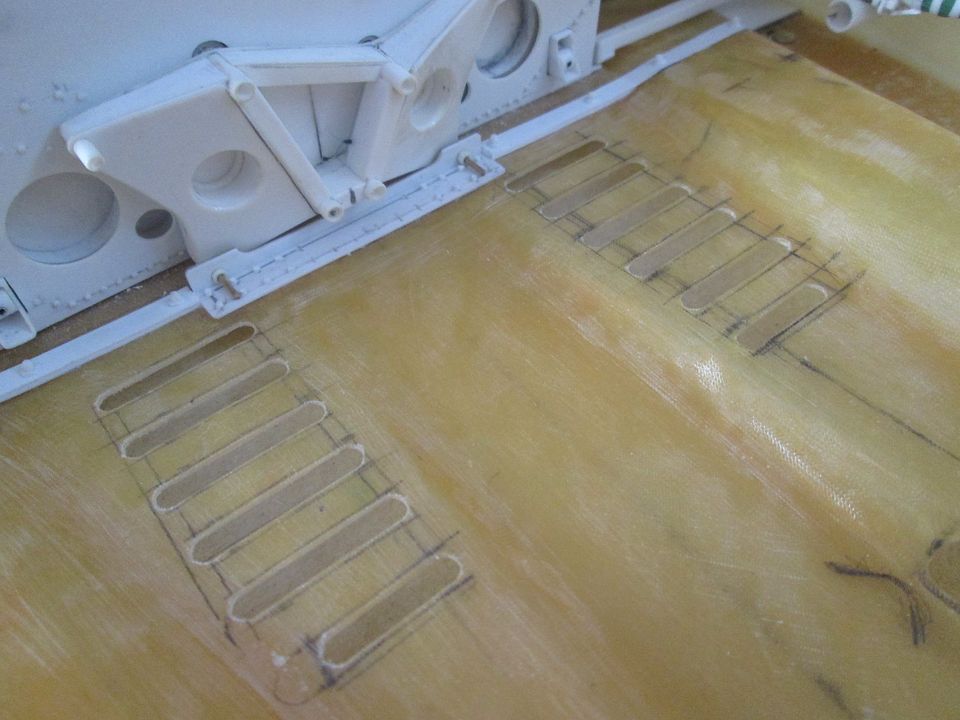 Moving on, I've spent the last few weeks working on various engine details. First up, the lower water rails which will connect to the two water pumps on the back of the engine: 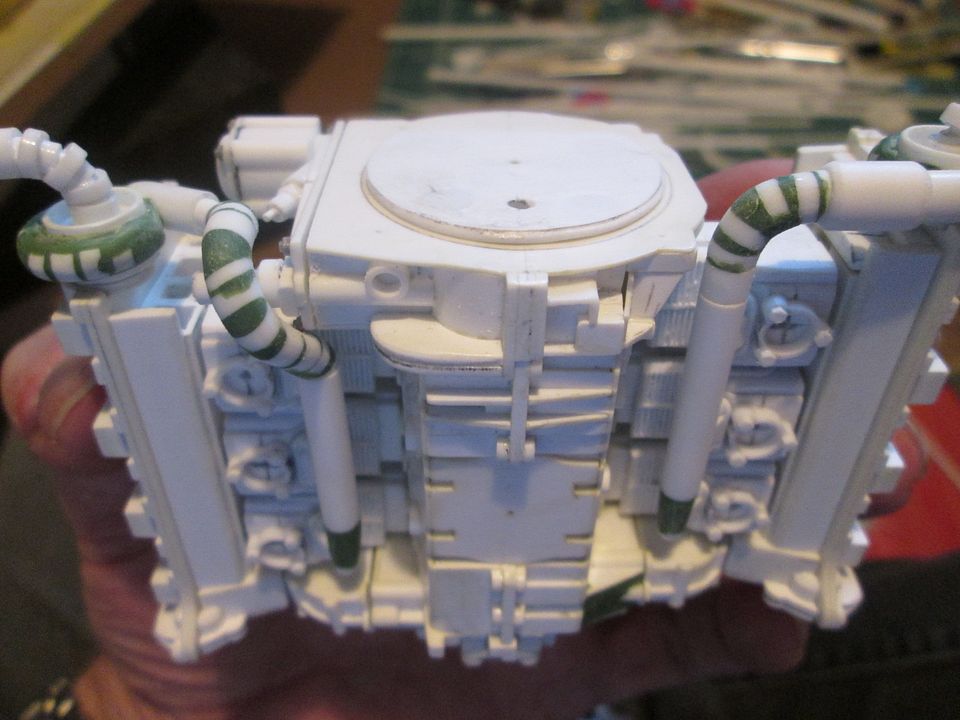 Similar to the exhaust pipes, the curved sections at each end were built-up from a wire core with layers of tube and Greenstuff to fill in the gaps. While making the left-hand pipework I had to finish off detailing the oil filter housing, as the main oil feed has to fit through the loop in the water pipe. 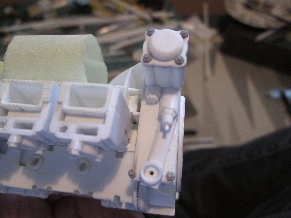 The upper rails were made in a similar manner: 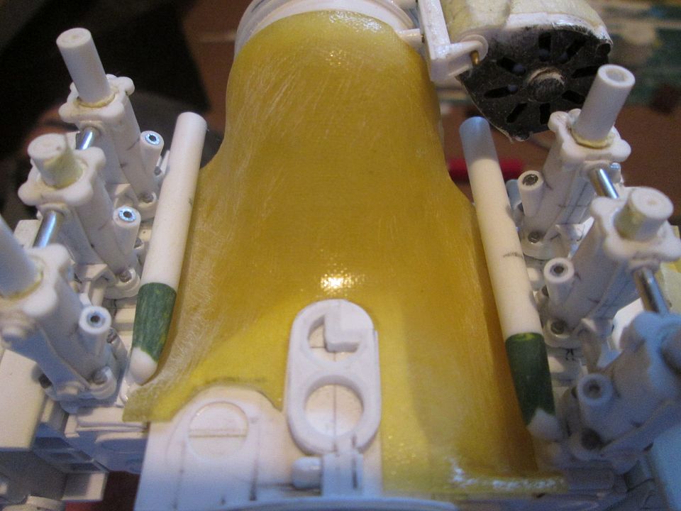 However, with these I also had to allow for the two downpipes which drop over the front of the engine and run into two holes in the back of the tub: 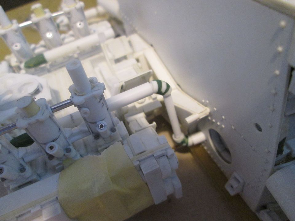 These are basically at the right length, but I will do a final fit later when the engine is in position. Not shown here, but I've also added a couple of socket details on each pipe which will be wired-up with temperature senders. Next on the list of engine details - distributor cap and plugleads: 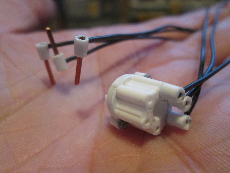 Not the best photo, but you get the idea. The plug leads will get a little spot of filler in the top, and maybe a small length of heatshrink around the end of each wire for extra detailing. I've also made the six Z-shaped retainer brackets which are bolted to the cam covers over each pluglead - these will be fitted at a later stage after painting. As the original 956 engine used air-cooling for the cylinder barrels, it was still using the extra shroud panels which wrapped partially around the underside of each cylinder, to get more airflow before exiting out of the bottom. On the 935-78 I made these by cutting and bending thin aluminium, but for the 956 I went for a less frustrating method: I made them from styrene: 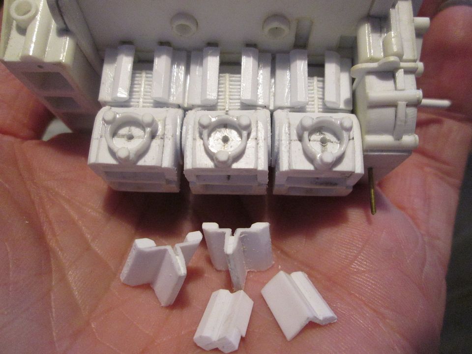 Much easier to make - short lengths of angle-section, some strip, and a bit of filing afterwards. And they'll be completely invisible once the model is assembled... The final job for this update has actually been several jobs, but they're all connected. I felt it was time to start assembling the cylinder heads properly, as this was stopping me from making progress with other things. Part of my reluctance to do this was the thought of painting some of these parts separately, but I came to the conclusion that it shouldn't be an issue. So, I've fitted each head to the cam cover, and this in turn has allowed me to add the half-round detailing along the top and bottom edges. Most of these will be detailed with hex-nuts, but a few will be left blank for now to allow for plug-lead holders to be added. I've added the base-plates for the two cam-box oil pumps to the front, and have blanked-off the un-used ends of the upper camshaft drives. On the left-hand side I've added the support rib for the fuel injection pump - although I won't be using this as my 956 is on Motronic fuel injection, it is a feature that Porsche didn't (or possibly weren't able to) remove from the cam cover casting: 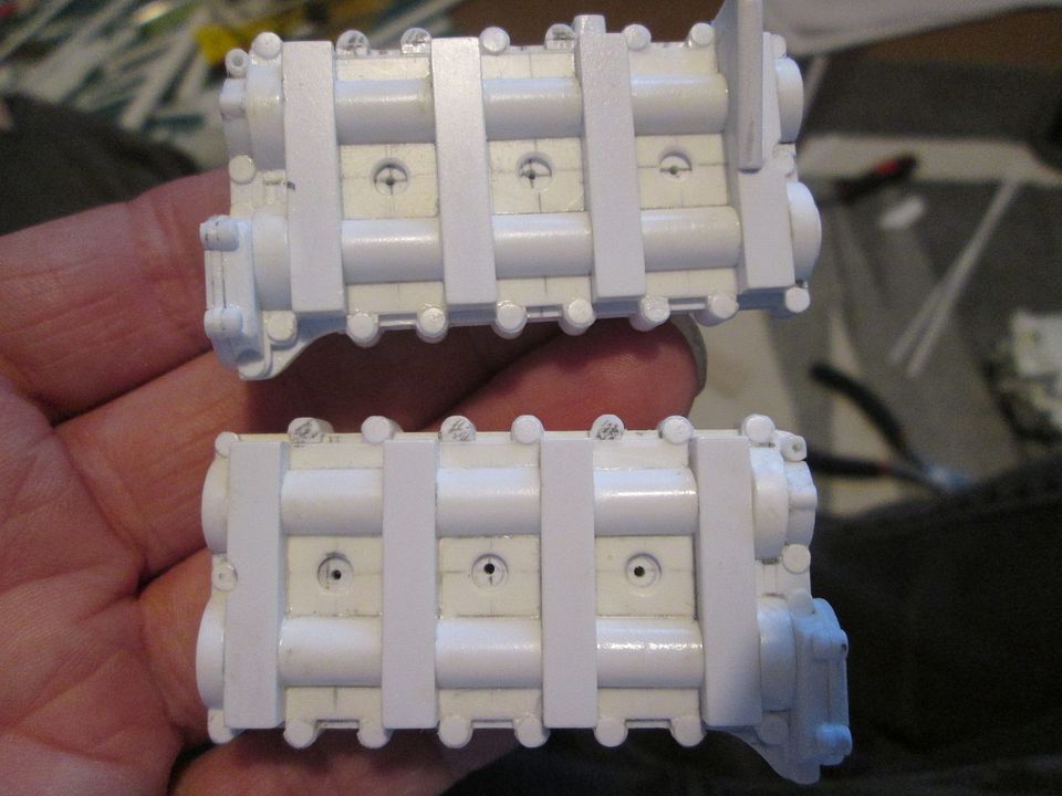 On the subject of hex-nut detailing, I ordered another bunch of the 'Wave Option' hex-nuts from HobbyLink Japan last Tuesday...and they arrived today! Fantastic service, and much appreciated. That's where I am as of today, then. I can now add more hex-nuts to the cam covers, etc, and hopefully fit a few more engine parts together. Maybe spend the rest of this week fiddling with the engine, before starting something new at the weekend. I really must re-visit the front upper and rear lower wishbones at some point, so maybe it's time for them... All the best, SB |
|
|
|
|
|
10-11-2022, 01:39 PM
|
#130 | |
|
AF Enthusiast
Join Date: Sep 2011
Location: Redwood City, California
Posts: 651
Thanks: 0
Thanked 39 Times in 39 Posts
|
Re: 1/8 Porsche 956
Stunning work as usual! Thanks for posting,
ianc |
|
|
|
|
|
10-11-2022, 03:49 PM
|
#131 | |
|
AF Newbie
Join Date: Oct 2020
Location: Netherlands
Posts: 57
Thanks: 7
Thanked 8 Times in 7 Posts
|
Re: 1/8 Porsche 956
Nice work SB,
lots of details to look at, cant wait to see some paint on it. Just wondering how the mechanics worked on this engine, was the floor detachable or how did they do it? Greetz Peter
__________________
Thx for watching, Greetz Peter
|
|
|
|
|
|
11-21-2022, 04:11 PM
|
#132 | |
|
AF Enthusiast
Thread starter
Join Date: Nov 2008
Location: Norwich
Posts: 649
Thanks: 21
Thanked 111 Times in 87 Posts
|
Re: 1/8 Porsche 956
Hello again,
Firstly - sorry, Peter. I was going to post another update a couple of weeks ago, but got into that 'I'll just do a few more jobs first' mindset, and I should have replied to your comment earlier. Yes, the rear underfloor on the 956 was removable - in reality it was split across the back of the tub so the sidepods could stay on the car, but I've extended it all the way to the front wheelarches to try to improve the strength. The rear side panels would also come off the real car quite easily, but again, I've made them as a single panel for strength. Removing the main tail section will show enough of the engine and gearbox detail. So, at the start of last month I was still adding various details to the engine. After making the water pipes, etc, I added the main oil scavenge pipe which runs under the right-hand side of the engine: 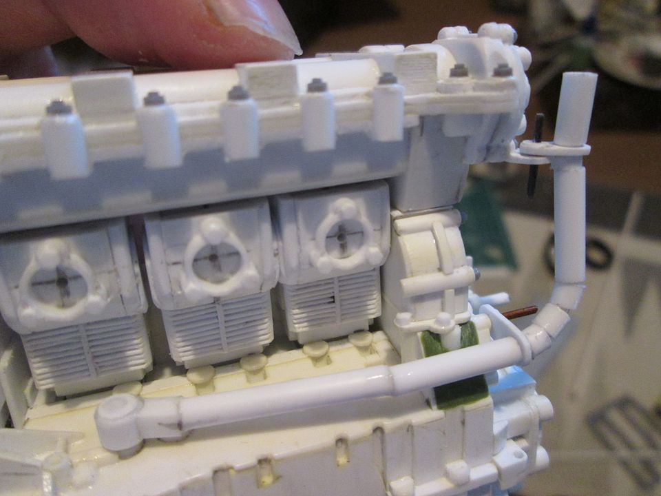 As usual, this is a wire core with 1/8" styrene sections added to create the pipe. There's a couple of small mounting brackets to hang it from the front of the engine, and in time it'll get some take-offs for the smaller pipes to the two cambox oil pumps, and some greenstuff to fill in the gaps. Next, some details for the gearlinkage: 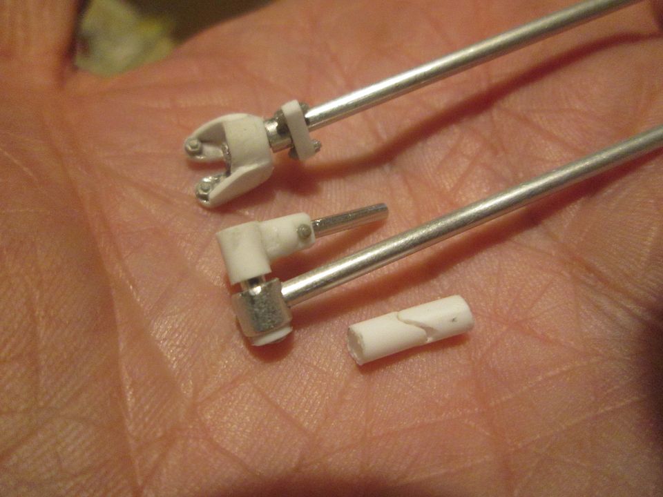 The upper part is a small mounting bracket which sits on the gearbox 'ox-bow', and the section of linkage that will run back to the tub. The bit in the middle is the final section of linkage (in aluminium) connecting to the shift lever in the top of the gearbox itself. The final bit is a small universal joint that will be inserted into the linkage just behind the ox-bow mounting. The next job was to finally return to the front upper suspension. The upper wishbones on the 956 / 962 are connected to the uprights via a machined block (of varying designs) which combines a pivot for the wishbone with a steering connection. I had a first attempt at making these top blocks a while ago but wasn't happy with the result - I was struggling to incorporate an RC-car balljoint into the box-section (to improve the strength), and the wishbone itself was too 'lightweight' in reality to translate into 1/8 scale with any durability. So, as is often the case, I put it all to one side for a while in the hope that a better solution would develop... And it did. The first breakthrough was finding that amongst my stash of small RC balljoints, there was a couple that were smaller than all the others - small enough to work better with what I was trying to do, and more in-keeping with the overall size of the model. The second change was that rather than trying to use 3/16" box section for the main body of the top block, I would fabricate it from a mix of 3/16" box and 0.75mm sheet: 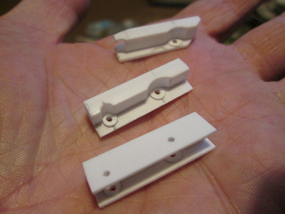 The top one is a trial part I made to get a feel for the size and shape, the other two are the final parts in-progress. You can see where I've put recesses into the box-section to provide clearance for the wishbone and trackrod pivots. The little styrene washers are enough to close-up the gap for the RC balljoint. The finished thing looks like this: 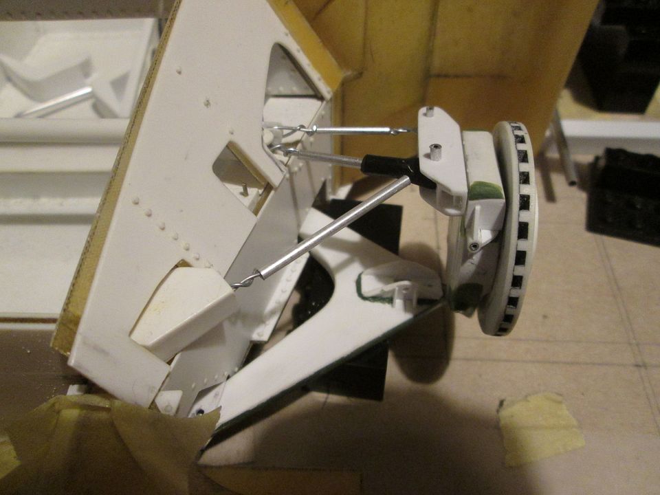 The top block is pinned through into the upright for strength. I've used ali tube to create the pivot pins for the steering and wishbone, and made all the little wire 'rod end' joints to connect everything together. The ali tubes will get a styrene outer layer when I start finalising the geometry. The forward joint on the top wishbone leg is pinned into a smaller section of box which simply pushes into the main chassis pick-up, which will make final assembly much easier. Overall, I'm very pleased with the result. While still in front suspension mode, I could now start on making the front anti-roll bar. A simple enough part in theory, but still a mini-project that took a good week or so of work. Firstly, it's not a simple straight bar - it has a curved section on the driver's side to allow it to clear the steering column. Second, instead of being held captive each end in a pair of blocks, the 956 bar appears to pivot about a single fixed point at each end. Third, I have to make it possible for both ends of the bar to rotate independently of each other, to allow the bar to fall into place naturally when placed on the suspension. So, I started by marking out the basic measurements on a piece of cardboard, and putting together some styrene tube sections onto lengths of plastic-coated wire: 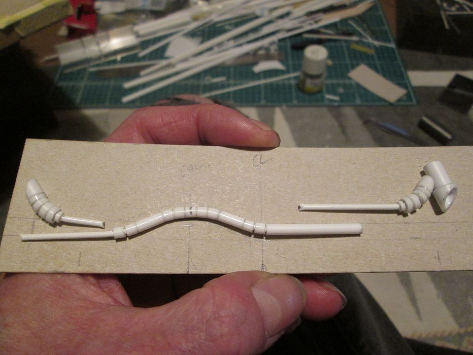 Each end of the bar curves backwards slightly before the 'cup' for the adjustable blade is added. The mounting block you can see here is 2.5mm wide, and the hex-nut detail is 1.5mm. Eventually this will be drilled and pinned into the top of the chassis tub. 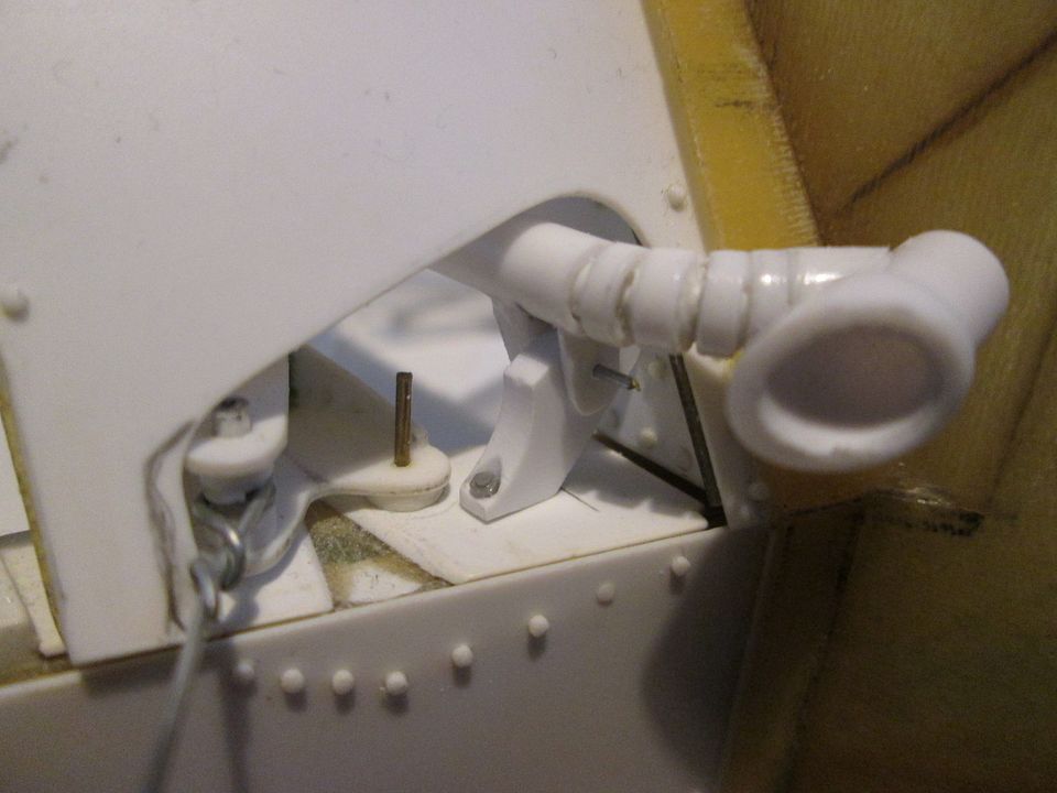 After some more work and some greenstuff: 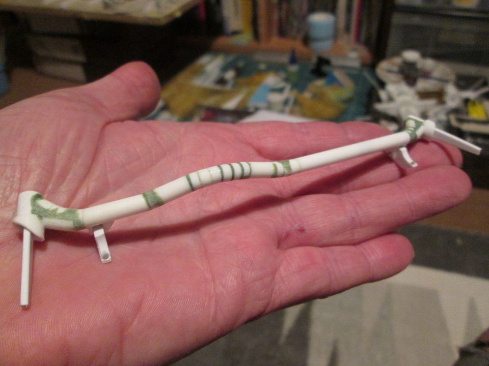 The main bar is actually in three sections - The right hand-end complete with the curved section, a middle section with the left-hand mounting block, and the left-hand end. There is a stack of small magnets inbetween, so the whole lot clicks together quite nicely while still allowing the two ends to rotate! I just need to make some drop-links down to the lower wishbones, and some adjuster caps to fit on the ends of the two blades. The final photo for tonight is what I'm working on at the moment - refining the rear suspension: 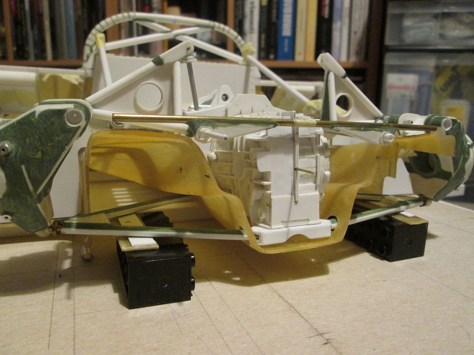 The lower wishbones have been updated by adding styrene and greenstuff to the edges of the ali tube to create a more flat-oval profile. I need to add a little more detail to the outer pivot for the base of the upright - that's a job for this week. The underbeam below the gearbox is a mk2 version - again, the original was supposed to be in a smaller section, but I've changed it to 5/16" x 3/16". This has allowed me to create 'plug-in' connections for the wishbone joints, and to add the curved section on the underside. After all that, I've redesigned the main connections between the top wishbones and the front end of the upright - my original plan was to incorporate some more magnets here, but on reflection I wasn't happy that this would be strong enough. I've changed to an arrangement which uses various sections of ali tube to pass a pin through the wishbone and into the upright, allowing it to rotate as the suspension moves, but not falling out again. I'll show a detail of this next time. In addition, I've been tweaking and fettling the fibreglass underwing - opening up the holes for the wishbone legs to pass through, giving enough wriggle-room to be able to get the wishbone into position during assembly, etc. At some point I'll open out the holes for the driveshafts too. There's a little more work to do in this area - for example, I'm still trying to decide if I can fix the rear mounting bar into position on the gearbox, or if this would be better left until final assembly. I also have to make some top toe-links and their connection to the uprights, and the short arms on the top wishbones for the roll-bar links. At some point I also have to make some flexible brake ducting and the detailing on the mounting bar... So, that's everything pretty much up-to-date for a while. I'll aim to do another regular update in a few weeks, and then a final 'New Year's Eve' post with the traditional 'here's a photo of everything I've made so far laid out on the desk'! I'm not sure that everything I've made will actually still fit on the desk, but I'll find out in a month's time! I'm planning to have next week at home, so I'll probably try to do something different - maybe finish making the dials, switches and warning lights for the dashboard, perhaps some more work on the fire-bottles, or the seatbelts, or...or...we'll see. Have a good week, SB |
|
|
|
|
| The Following 2 Users Say Thank You to ScratchBuilt For This Useful Post: |
NickChan28298 (12-19-2022)
|
|
12-31-2022, 06:23 AM
|
#133 | |
|
AF Enthusiast
Thread starter
Join Date: Nov 2008
Location: Norwich
Posts: 649
Thanks: 21
Thanked 111 Times in 87 Posts
|
Re: 1/8 Porsche 956
Hello again,
As usual, my plans for posting in the run-up to Christmas didn't quite work out, but as it's New Year's Eve again it's time for another end-of-year report! So, at the end of November I was looking at refining the rear suspension. I made some revised connections for the top rockers to the uprights using ali tube (which I still haven't photographed!), added some rear toe-links, made various shims and spacers to get everything the right position, then put the rear dampers together: 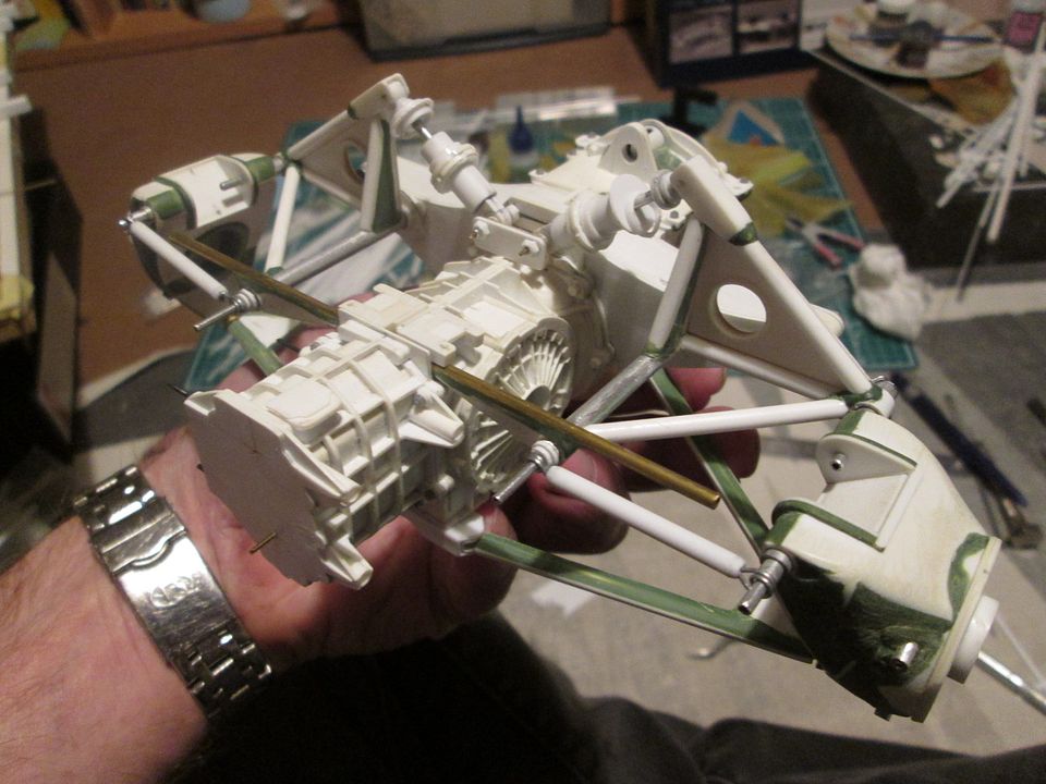 The spring platforms, etc, on the dampers are not fixed yet, and I'll add some external thread detailing later. The springs themselves are something I need to work on - on the real thing they're a combination of a tapering diameter main spring with what appears to be a helper spring - as with most things 956/962 it all depends on which car you're looking at. After the dampers, the next step was to complete the top rockers by adding the connection arms for the roll-bar droplinks: 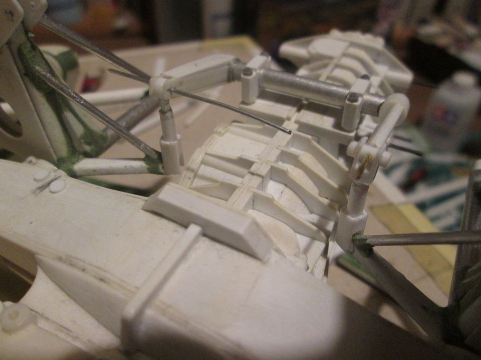 What's not obvious from this photo is that by this point I had re-made the top rockers! I based the original angle for the inner arms on the various photos I was using for reference, all of which suggested that they dropped down below the level of the outer section. Wrong! The pitfall of using photos and not thinking to dig out a drawing! So, rather than correcting the arms on the mk.1 rockers, I took the opportunity to re-make the whole lot. This allowed me to improve a couple of other small things that had been niggling me (one of the main pivot tubes, and the size of the outer housings), so at least I had the feeling that it was a positive step - even if it it did cost me a week of modelling time! The droplinks from the roll-bar are currently just pinned together - I don't want to glue them until the rear suspension is assembled properly, so I can be sure of the correct length and angles. The greenstuff on the mk.2 rockers needs a little refining, too. Next up, a few 'small jobs'. The mounting bracket for the water header tank was cut and bent from thin aluminium, and will be pinned into the duct: 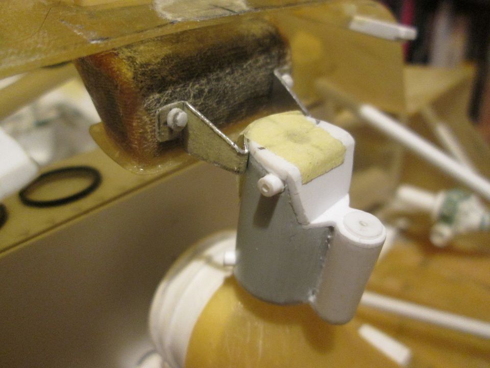 Turbo boost control knob, to be mounted under the dashboard: 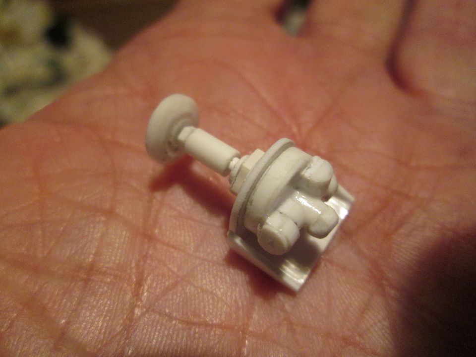 Fusebox covers: 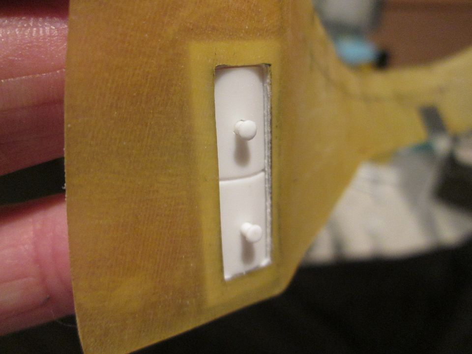 For the last couple of days I've returned to the fire extinguisher bottles and mounting. I made the basics of these some time ago, but final detailing was required. The drawings I'm using clearly show a two-bottle set-up, but most of the photos you find are of a single bottle. I couldn't find a single 956 photo showing how two mechanical bottles were operated using the two pull-cables (given that each cable has to operate both bottles). So, I've used the Heinzmann arrangement, similar to the 935-78, where the cables pass through one lever, then the second: 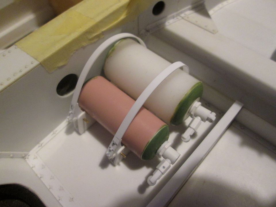 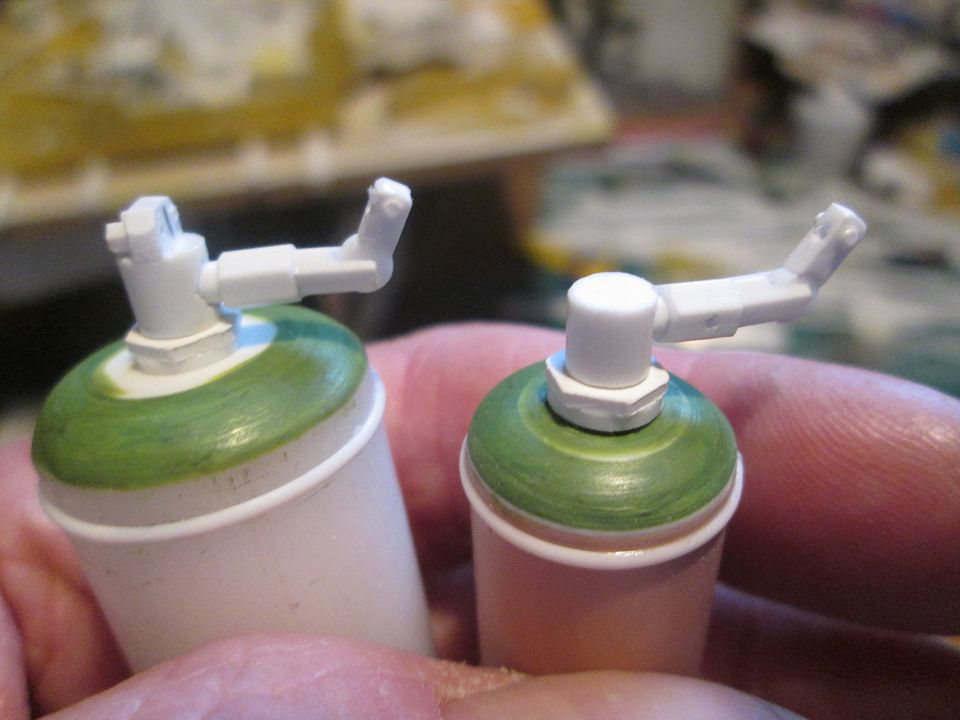 Attaching the pipework to the bottles will be fun as they will be on the underside of the firing heads, but I'll deal with this later - at least it's not tucked away under a dashboard this time. The mounting straps are pinned at the rear end, and push into place at the front. As I suspected, the 956 'kit of bits' has now outgrown the tabletop I usually use for my end-of-year photos, so yesterday's project was to transfer it all into my bedroom / workshop! Here's where we are after four years: 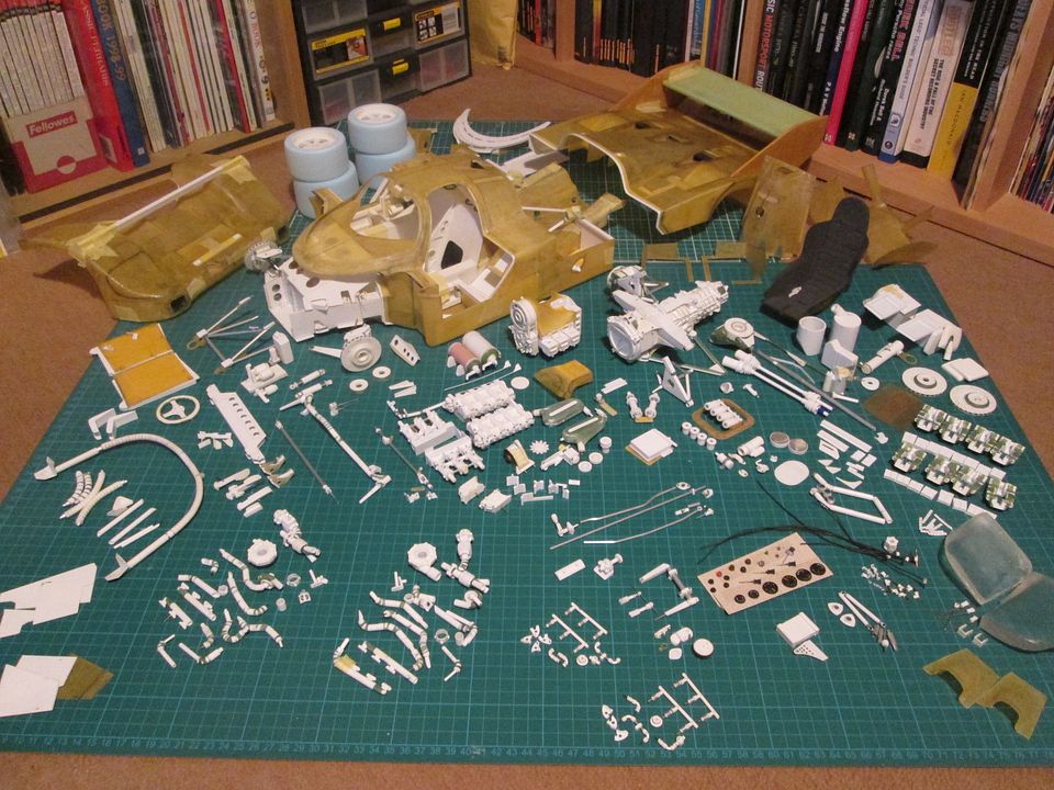 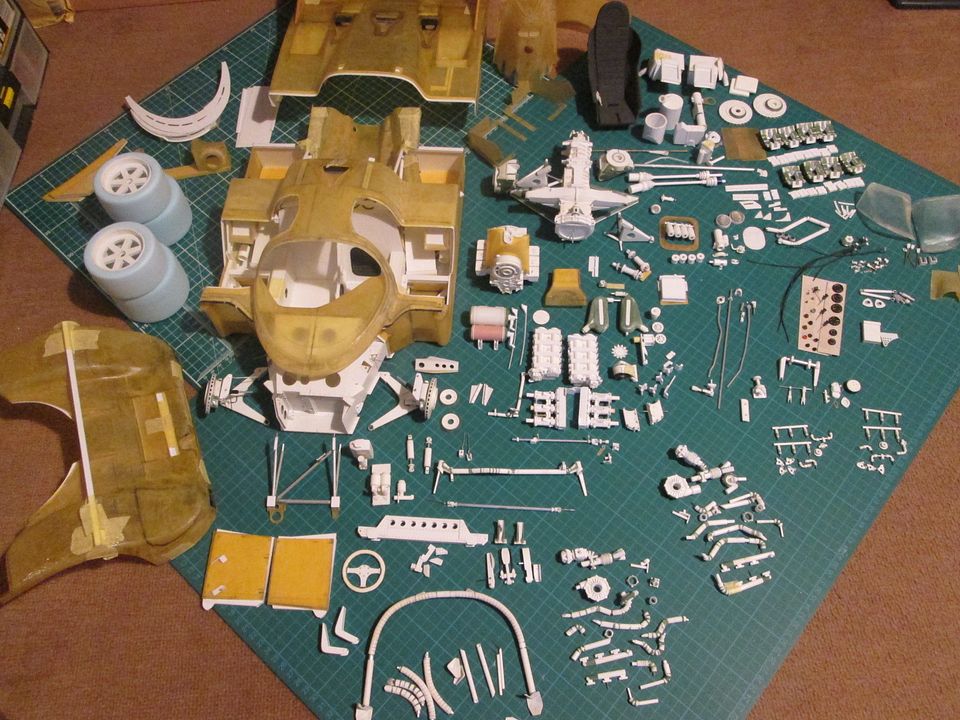 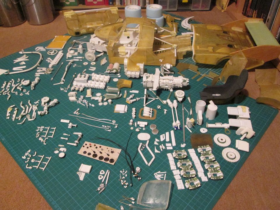 There's one or two bits here that I haven't mentioned in posts - for example, the instrument dials have been painted and are ready to be filled with clear resin, and I've made the warning lights, buttons, ignition key, etc. There's an electrical connector for the tail (just next to the rear dampers), too. While I was setting everything out there were a few things that I didn't immediately recognise - 'what did I make that for?'...but then it falls into place! I've put together an A4 page of parts that still have to be made, and that doesn't include all the things in the photos that need a few adjustments or extra detailing during assembly. I'm going to have to start painting and sub-assembling some of this during the next six months, as I need to keep the momentum going. I'm also very aware of the fact that I haven't decided on a livery for this 956 yet, and that I have done very little on the doors so far...! As always, thanks for following what I'm doing, and I hope that it continues to be of interest. Wishing you all the best for 2023, and more model-making ahead! SB |
|
|
|
|
| The Following 2 Users Say Thank You to ScratchBuilt For This Useful Post: |
mrgixxer (12-31-2022)
|
|
02-07-2023, 03:18 PM
|
#134 | |
|
AF Enthusiast
Thread starter
Join Date: Nov 2008
Location: Norwich
Posts: 649
Thanks: 21
Thanked 111 Times in 87 Posts
|
Re: 1/8 Porsche 956
Hello again!
I started January by tackling the two fuel filler necks which run from the top of the chassis tub to the sides of the cockpit bodywork - I felt it was one of those mini-projects that I could probably get completed in a week. The construction itself was relative simple - create an elongated S-bend section from increasing sizes of styrene tube, adding more layers as the filler neck gets closer to the bodywork. However, it was another one of those jobs where you have to work everything out with the bodywork in place, so access is restricted and you can never quite see as well as you'd like! 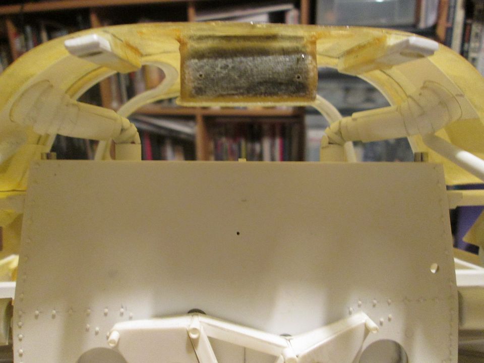 You can see here where I've added the extra layers to both reinforce the bends, and to get the core the correct size. A further complication was that the two fillers are not identical - the cut-outs in the tub for accessing the bag tanks are not equispaced on the centreline. Happy with the overall shape, the next step was to apply Greenstuff and smooth it all off. I also made a couple of ring collars which will be fitted onto the top of the tub: 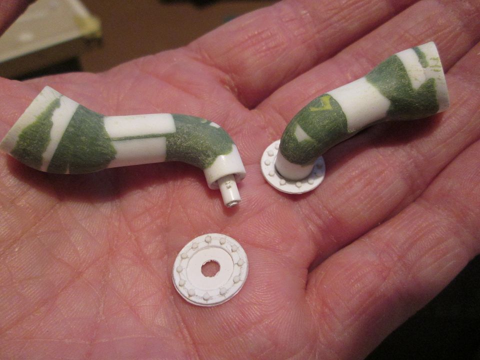 The next mini-project was to make the small module for mounting the indicator / light stalks behind the steering wheel. It's the sort of detail that doesn't show up too well in a lot of the photos, or if it's there it's from the same angle every time! Okay, it's not the most exciting part of the car, but there's enough info to make something that looks right: 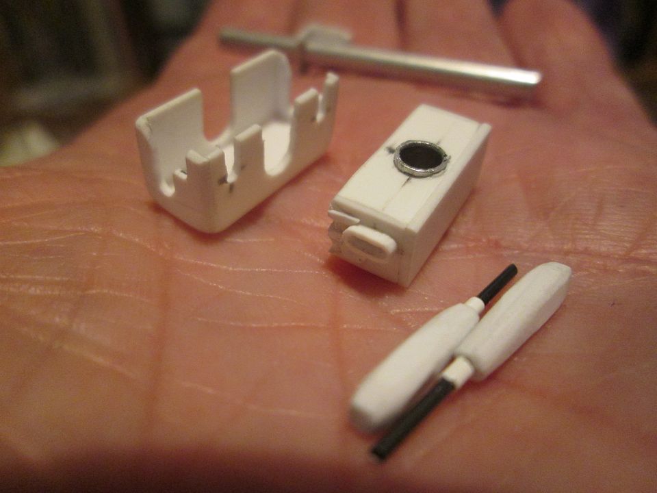 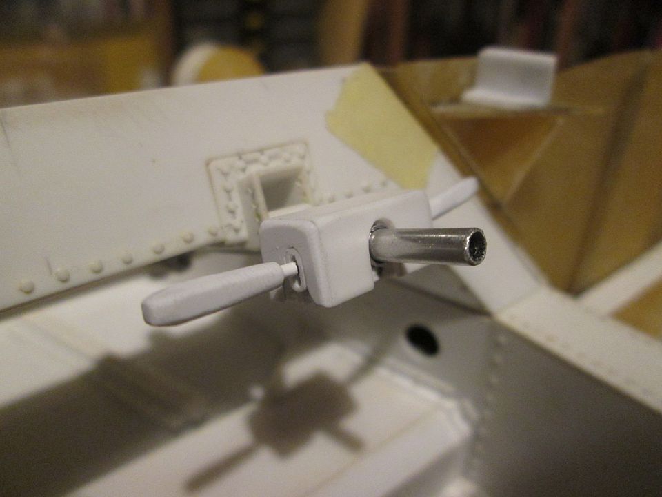 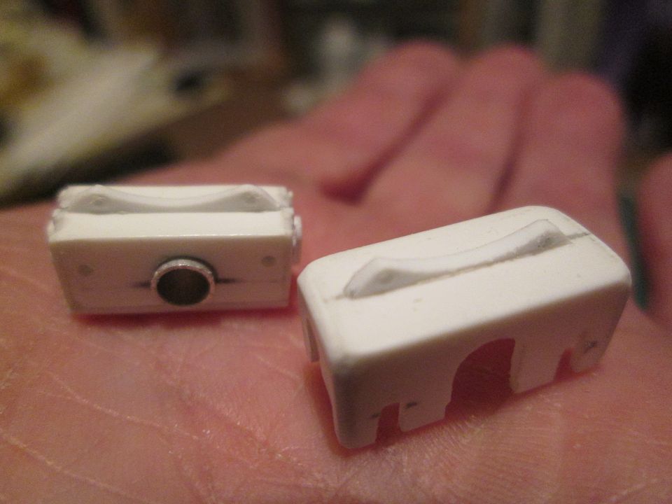 I could see from the reference photos that the main body is a two-part 'box', with the stalks and electrical gubbins in the lower section, and a cover fitting over the top. I wanted to make mine in the same way, so you can see where I've had to put slots in all the openings on the cover to fit over the steering column and the wiring which will connect to the back. For the last couple of weeks or so I've been tackling the very exciting job of making most of the pipe connections for the fuel and oil systems. I spent a couple of evenings drawing layouts for the various systems, cross-referencing this with the books and photos, then making a chart of everything I would need to make. In several sizes, to suit different sizes of hose. Oh joy! I ended up with a list of fittings in six different sizes (reduced to five for practical reasons), with a mix of straights, bends, banjo fittings, T-pieces, etc. First up, here's most of the fittings for connecting the oil coolers, with fittings for the turbo lubrication in the small plastic bags, and two larger fittings for the main oil feed to the engine. In real life, this is a mix of -8, -10, -12 and -16 unions: 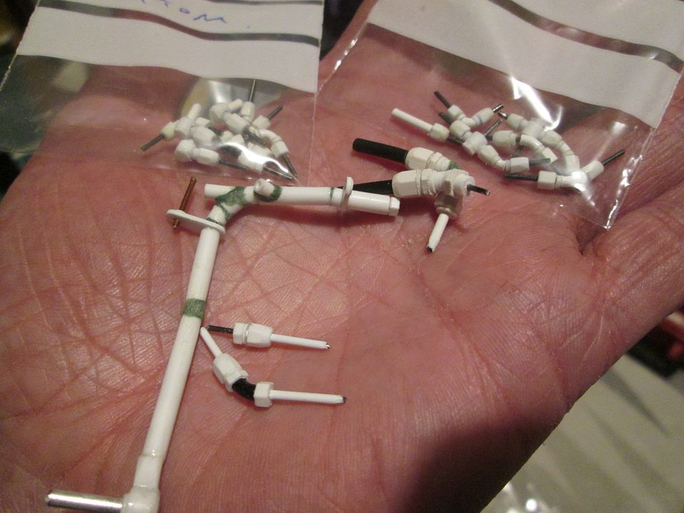 The oil coolers will be piped in series from one side to the other, so there's an aluminium pipe mounted to the back of the tub rather than a flexible line: 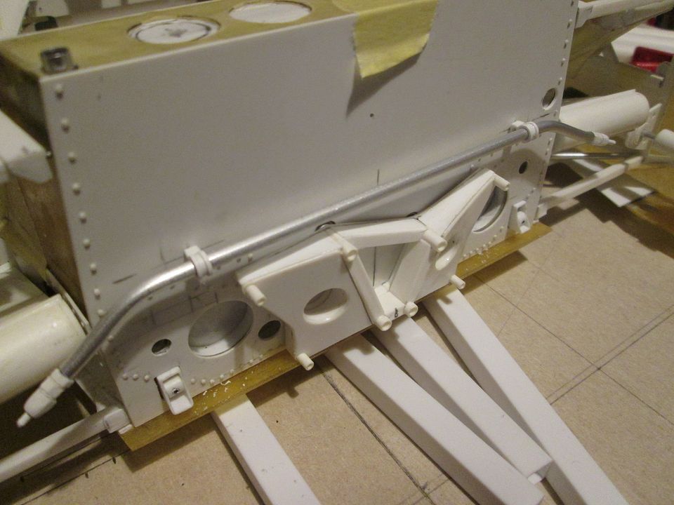 I've also added the pipe connections to the underside of the two oil coolers: 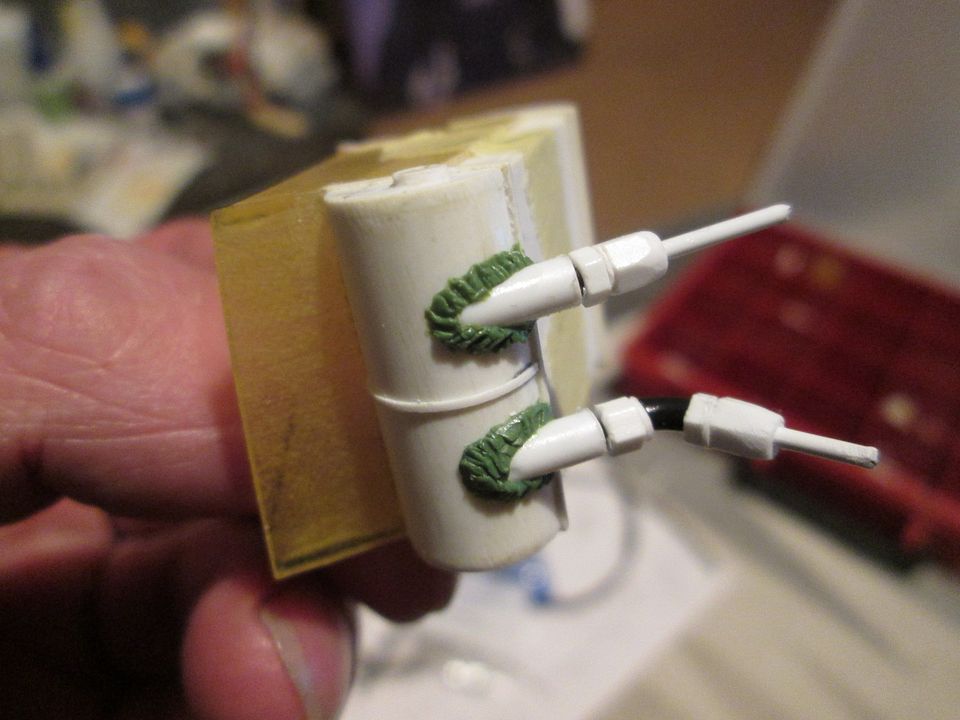 Finally, here's the smaller -6 fittings for the fuel system...all 36 of them: 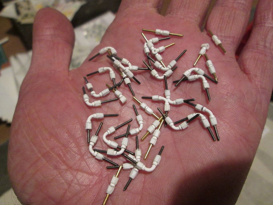 While doing all this I've also re-made the four fuel filters that will sit in the cockpit by the fuel pumps, plus more fittings for connecting the water header tank to the intercoolers. I still have to make the fittings for the gearbox oil cooler, and everything that will be required for the brake and clutch system, so that's probably another 20 or more unions! Maybe I'll leave these for another time... My next job is to start adding some brackets and retainers to the back of the tub for the wiring and plumbing - there's a lot of stuff coming through the bottom of the tub and looping up around the top of the engine, and most (all?) of it has to go behind the ali crosstube. I have some good photos of the Richard Lloyd 'Canon' 956 (106B) with the all the wiring and piping on display (and no engine fitted), but it's worth remembering that this car was built with a modified tub, so there are bound to be slight differences. As always, I'll be looking at as many of my photos as I can, and hopefully combining it all to create something that works. All the best, SB |
|
|
|
|
|
02-08-2023, 09:37 AM
|
#135 | |
|
AF Regular
Join Date: Feb 2005
Location: Kaatsheuvel
Posts: 221
Thanks: 26
Thanked 45 Times in 40 Posts
|
Re: 1/8 Porsche 956
Now why would you even consider buying a model kit ever again? You will scratch build everything in for greater detail. Mind blowingly interesting to see this progress. And still very inspiring to level up my next build again.
|
|
|
|
|
|
 |
POST REPLY TO THIS THREAD |
 |
|
|


