|
|
|

|
|
| Search | Car Forums | Gallery | Articles | Helper | AF 350Z | IgorSushko.com | Corporate |
|
| Latest | 0 Rplys |
 09-19-2009, 06:45 PM
|
#61 | ||
|
AF Enthusiast
Thread starter
Join Date: Aug 2005
Location: where "sky grey" is a colour
Posts: 822
Thanks: 3
Thanked 32 Times in 29 Posts
|
Re: Jordan 191
Quote:
Thanks everyone for the comments. Theyre much appreciated :-) During the week I finally did another run of photoetching, redoing some parts that didnt come out nice enough the first time or where I got some measurements wrong. So now I can get on with some areas that were missing these last parts. The first area I can show you is the front wing of which I had already shown you some steps. I spent a good deal of time thinning the endplates. I sanded them to about 0,4mm wall thickness in all the areas where it shows ( which unfortunately was most :-) Here you see a comparison of the thinned left one vs. the unchanged right endplate. 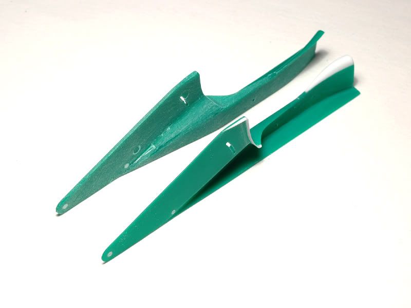 I then added the white bits from sheet styrene. The curvy parts ( vortex generators I guess ) at the rear end were formed with heat over a file that conveniently had the right shape. I opened the slots for flap adjustment and reduced the size of the holes for the locator pins on the wing, as these will be replaced by more accurately sized brass pins. 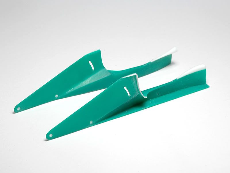 As I mentioned at the very beginning of this WIP the front wing flaps in the kit are too big ( more downforce ) for the Spa race. So I modified the outer adjustable ones. I then etched Gurney flaps for them plus new inner flaps. The etched parts especially for the Gurneys required some tricky bending and squeezing but ultimately worked as planned :-) 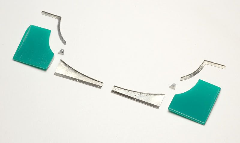 So heres another shot of all the pieces laid out together. They are now ready for some paint. 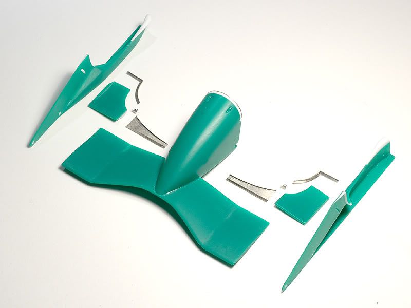 Thats it already for today but theres more to come :-) |
||

|

|
|
09-20-2009, 03:10 AM
|
#62 | ||
|
AF Regular

Join Date: Aug 2005
Location: Johannesburg
Posts: 171
Thanks: 3
Thanked 0 Times in 0 Posts
|
Re: Jordan 191
Quote:
I'd like to ask a couple of questions about that last item: 1. How do you get the slot in the endplate so neat (especially for a curve)? It seems pretty narrow (I'd guess about .3mm?), and I've not seen a file that size. Are you using a micro milling machine, or is that some great tip you could share? 2. The glue work seems really tidy - MEK/Tenax or what? 3. How did you shape those "lips" that look like Gurney flaps? If I had to guess I would think you'd glue .5mm sheet styrene to those edges of the endplate, carve off the excess then sand back to thin and taper the edges. Would that be right? PLease keep the updates coming - this is better than getting magazines in the mail! |
||
|
|
|
|
09-26-2009, 09:17 PM
|
#63 | |
|
AF Regular
Join Date: Jul 2003
Posts: 446
Thanks: 5
Thanked 1 Time in 1 Post
|
Re: Jordan 191
WOW Man. This is even more sublimer than the other stuff. You guys are incredible. I love it how you are the hero to our hero's...That is so cute.
Adjectives fail to describe your work other than total admiration and respect. I too am a fan of just building, so I don't care if you don't paint it. I love watching your scratchbuilding. To me that is at least 70% of the fun in modelling. I look forward to further progress on this inspirational journey. Cheers Nens
__________________

|
|
|
|
|
|
09-27-2009, 08:40 AM
|
#64 | |
|
AF Newbie
 Join Date: Dec 2008
Location: Scotland
Posts: 39
Thanks: 0
Thanked 0 Times in 0 Posts
|
Re: Jordan 191
speechless!!!!!!!!!!!!!!!!!!!!
|
|
|
|
|
|
09-28-2009, 12:36 PM
|
#65 | ||||
|
AF Enthusiast
Thread starter
Join Date: Aug 2005
Location: where "sky grey" is a colour
Posts: 822
Thanks: 3
Thanked 32 Times in 29 Posts
|
Re: Jordan 191
Quote:
While i do have very thin round and square files ( square one is 0,5mm at the tip and the round one 0,3mm ) i didn't use them here. I drilled a row of 0,3mm holes ( guided by the indentation on the kit part ), removed the left over material between the holes with a sharp surgical blade and then sanded the edge smooth with 600 grit sandpaper. Quote:
Quote:
Hope that answers your questions :-) New update will follow shortly. Cheers Jaykay |
||||
|
|
|
|
09-28-2009, 01:52 PM
|
#66 | |
|
AF Enthusiast
Thread starter
Join Date: Aug 2005
Location: where "sky grey" is a colour
Posts: 822
Thanks: 3
Thanked 32 Times in 29 Posts
|
Re: Jordan 191
Here comes some more building progress. It is less than I thought because the rear suspension is turning out to be very tricky. Many bits to scratch build and align
:-)
I wanna start with something else though the exhaust pipes. The kit parts are the typical Tamiya bits that benefit from further detailing. I started by cleaning the mold lines up and sanding them a bit more round where needed. Then I went a bit further and built this accordion like ( or whatever you may call it :-) section the Perfect Manual shows and that Tamiya just turned into a massive blob. I made it from 0,2mm etched washers. Not the quickest way but making it on a lathe would be rather tricky because of the very thin fins. 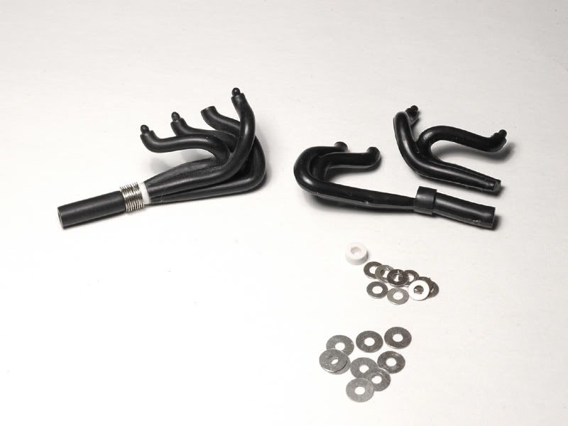 On the left is one pipe already assembled, on the right you see the raw parts. I then carried on and added etched mounting plates where the exhaust connects to the engine block. They will later hardly be visible but there are even little bolt heads facing outside ( yes, honestly :-) Then I added weld lines and some flanges with styrene and now the parts are ready for some paint. 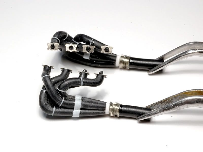 So now on to the rear suspension or actually the first part of it. That thing will keep me busy for some time to come In the first picture you see the lower arms. The upper left is of course the kit part ( all in one ) and to the lower right the modified part for the left side. Just like on the front I snapped of the ends and replaced them with scratch built rod ends plus hex screws made from brass tubes. I also added etched mounting points for the push rod and toe link and another one of those brackets made from black plexiglass. 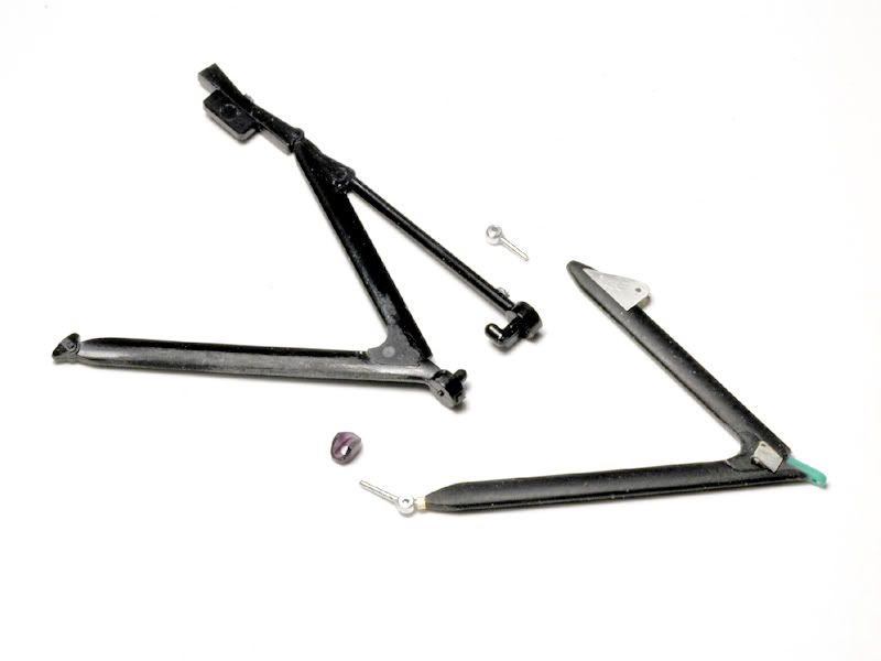 It took quite a while to tweak the kit part until it properly mated with the gearbox and my new upright. Once that was done making the pushrod and toe link wasnt so difficult though :-) The kit pushrod had to be shortened a bit for the rod ends. The toe link is made from 1mm brass tube. 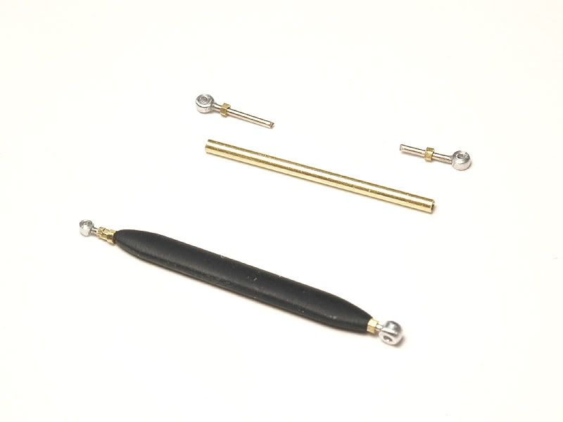 At the top of the gear box the pushrod is connected to what I call damper pivots. Dunno if thats correct!? Well they are the pieces that connect the pushrods with the dampers :-) Since the Tamiya parts are inevitably a bit blobby I made new ones from turned aluminium and etched bits ( superglued ). 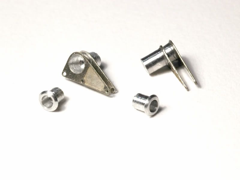 To connect the modified suspension parts to the gear box it also needed modifying. I added etched plates for the forward mounting points and a bracket made from an etched piece and some sheet styrene at the back. For the damper pivots I turned aluminium liners. Once the engine is painted these should look a lot like on the original gearbox. 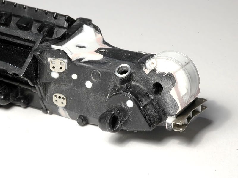 The final gear housing still needs a good deal of work. I went a bit in the wrong direction there. That has to be fixed together with the upper suspension arms. Another big job were the rear brake ducts. They come as one piece with the uprights which isnt helpful for painting and CFing and anyway the uprights needed improvement :-) More importantly the kit ducts arent Spa-spec. For the Belgian GP Jordan used versions with additional periscope style ducts. I made these from 0,3 and 0,5mm sheet styrene ( and body filler ) and also closed the lower ducts from the inside that way. 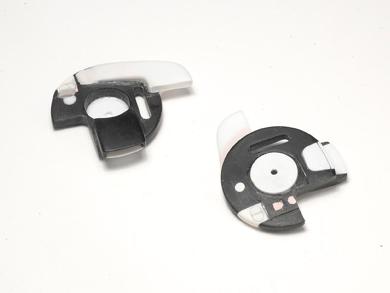 The black portions are modified Tamiya part and the white is added you get the picture :-) The parts also tell a little story about my trouble finding the right place for the hole that the toe link will pass through. Well, on the left one I finally found it :-) So after all the pictures of the individual parts here are some shots of them dry mounted on the gear box: 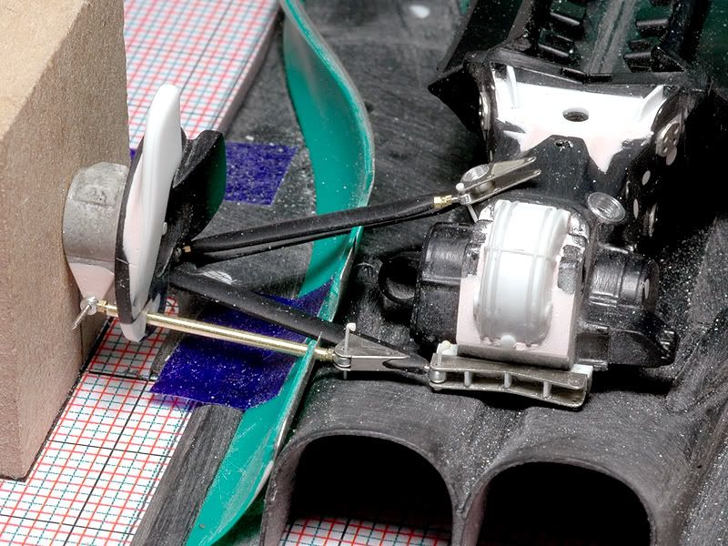 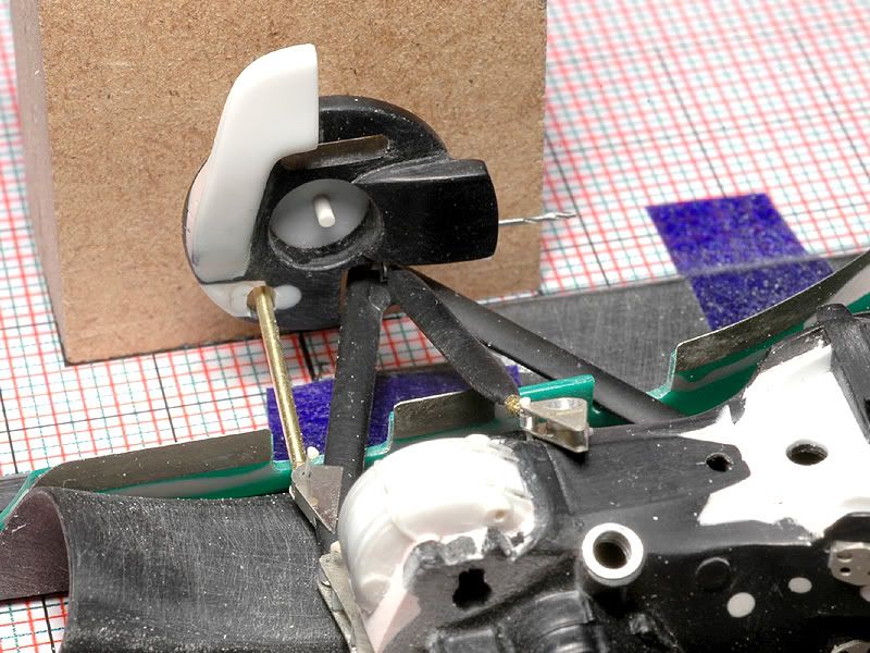 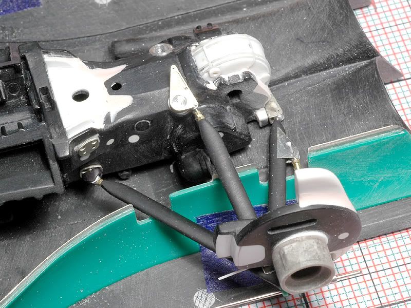 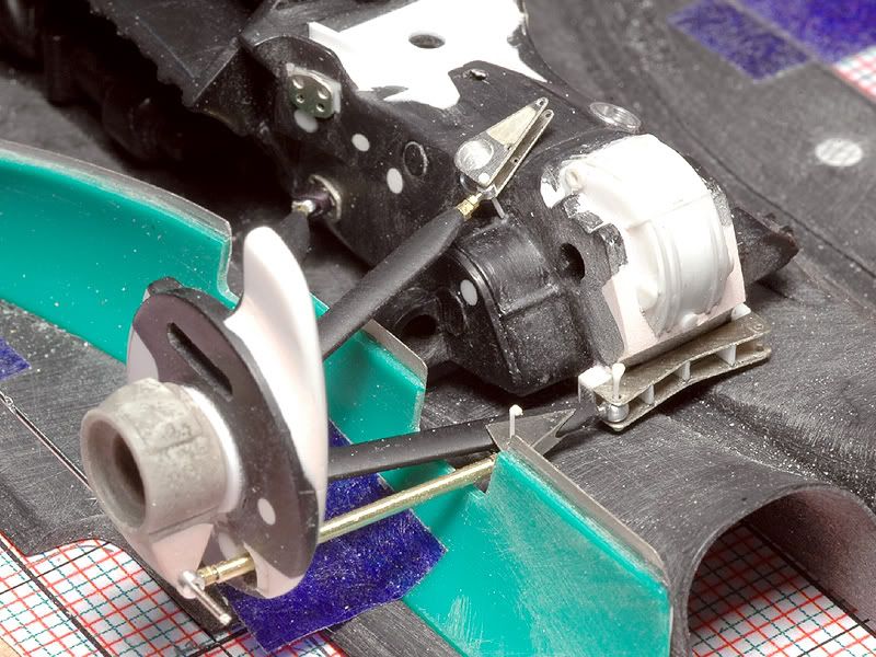 As I said before, it took more time than I initially thought, I only built one side so far and the upper arms promise to be even more time consuming. My next project will be curbside and have fenders ! :-) Thanks for looking again! More to come later |
|
|
|
|
|
09-28-2009, 02:29 PM
|
#67 | |
|
AF Regular

Join Date: Sep 2008
Location: Jacksonville, Florida
Posts: 310
Thanks: 11
Thanked 3 Times in 3 Posts
|
Re: Jordan 191
Jay - I know we throw the word "amazing" around here on the forums quite frequently and admittedly a bit too recklessly, but I would say that this certainly qualifies as a truly amazing build. This is the type of build that inspires me to take my own modeling to the next level and I greatly thank you for that. I will be following this thread very closely and can’t wait to see what other tricks you have up your sleeve.
Thank you!! Stuart |
|
|
|
|
|
09-28-2009, 04:40 PM
|
#68 | ||
|
AF Enthusiast

Join Date: Feb 2003
Location: F1...
Posts: 1,410
Thanks: 3
Thanked 3 Times in 3 Posts
|
Re: Jordan 191
Quote:
 Ohh by the way the progress is still impressive  |
||
|
|
|
|
09-29-2009, 01:08 AM
|
#69 | ||
|
AF Fanatic

Join Date: Dec 2004
Location: Up the creek with no paddle
Posts: 5,888
Thanks: 7
Thanked 16 Times in 15 Posts
|
Re: Jordan 191
Inspiring and riveting thread jaykay
 Quote:
 I certainly hope not!!  DeNnis, I have been trying out the BSI series of c/a glues recently and have found them very nice to work with. They have a very wide range of c/a and epoxies. You might want to give them a try?
__________________
Guideline for happy modeling: Practice on scrap. Always try something new. Less is more. "I have a plan so cunning, you could put a tail on it and call it a weasel" - Edmund Blackadder Last edited by klutz_100; 09-29-2009 at 06:56 AM. |
||
|
|
|
|
09-29-2009, 03:06 AM
|
#70 | ||
|
AF Enthusiast
Thread starter
Join Date: Aug 2005
Location: where "sky grey" is a colour
Posts: 822
Thanks: 3
Thanked 32 Times in 29 Posts
|
Re: Jordan 191
Quote:
I have also used "Pascofix" and others. I prefer the thin stuff because it flows better between parts and i think it sticks quicker than gels for example. For building like i do it here fogging is not a problem anyway. Once paint is on i try to use very little glue. To reduce the amount needed and to make placement of parts safer i use all those little locator pins. |
||
|
|
|
|
09-29-2009, 03:56 AM
|
#71 | ||
|
AF Regular
Join Date: Aug 2005
Location: Johannesburg
Posts: 171
Thanks: 3
Thanked 0 Times in 0 Posts
|
Re: Jordan 191
Quote:
|
||
|
|
|
|
09-29-2009, 06:45 AM
|
#72 | |||
|
AF Enthusiast
Join Date: Feb 2003
Location: F1...
Posts: 1,410
Thanks: 3
Thanked 3 Times in 3 Posts
|
Re: Jordan 191
Quote:
Quote:
 |
|||
|
|
|
|
09-29-2009, 09:38 AM
|
#73 | |
|
AF Enthusiast
Join Date: Oct 2008
Location: Austin, Texas
Posts: 748
Thanks: 13
Thanked 25 Times in 21 Posts
|
Re: Jordan 191
Inspiring work Jaykay. The precision of your fabricated parts is remarkable.
|
|
|
|
|
|
10-17-2009, 06:15 PM
|
#74 | |
|
AF Enthusiast
Thread starter
Join Date: Aug 2005
Location: where "sky grey" is a colour
Posts: 822
Thanks: 3
Thanked 32 Times in 29 Posts
|
Re: Jordan 191
More bits
.still no paint :-)
As I predicted in the last update there was still a lot to do on the rear suspension. The right side lower wishbone was a much quicker build though than the first one on the left. Once you have figured out the dimensions a mirrored copy is quicker to do :-) But before attacking the upper arms I made new drive shafts. They consist of some etched parts, turned aluminium bits and brass tube. In the picture you have the parts spread in the front, a semi assembled one in the middle ready for paint and for comparison the kit part in the back. Having more parts makes painting in individual colours easier .no masking but careful gluing later on :-) 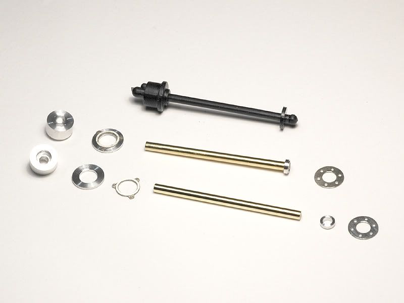 That done and finally focusing on the upper wishbones I realized however that the new final gear cover I had built from styrene earlier had its problems in places where the suspension and rear wing would be connected. I could have tried to work around that somehow but that promised to be messy so I decided to do a new better one. This time I machined it from Renshape and detailed it some more. Especially the flange where it is connected to the gear box is now a lot better than the first time. 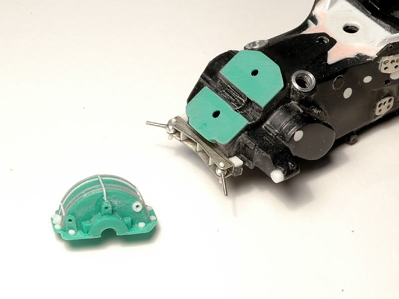 In the next picture it sits in its place. The really time consuming part was to get it sit in the right angle and get the mounting points right for the etched wing supports because if that was just a bit off the wing would possibly be angled and create even more headaches :-) 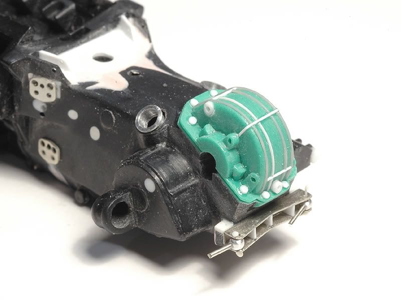 The next picture is of the upper suspension part from the kit. Its the same story all over as with the other ones it needs detailing. 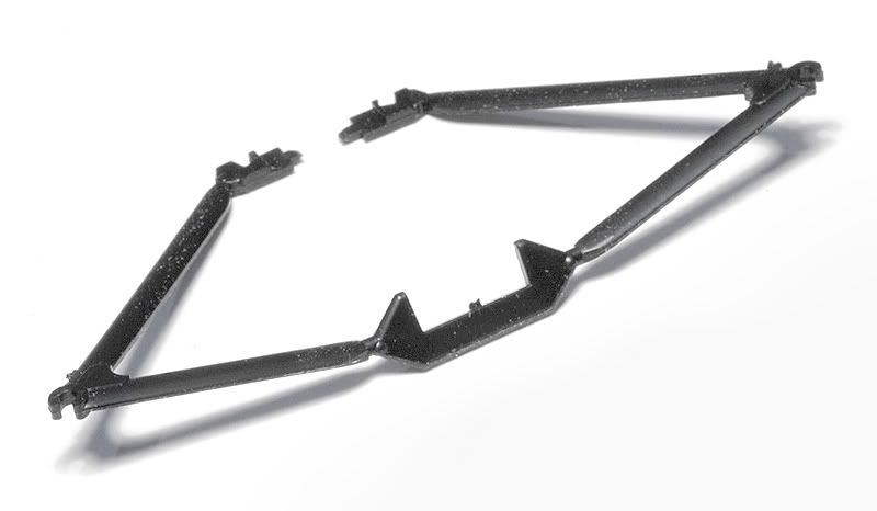 I replaced all the mounting points once more and had to tweak the angle and lengths. 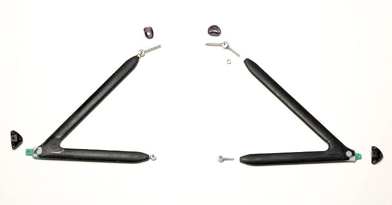 The time consuming part however were the little sub frames that Tamiya represented with those triangular blobs I scratch built them from Renshape cut to 0,2mm thickness. Here you see them in progress. 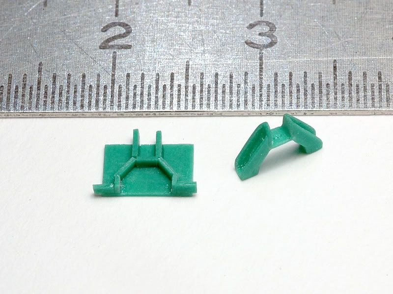 In the next picture you see them mounted to the gear box along with the wing supports. The subframes are in fact not yet finished ( they need additional mounting points for undertray supports ) but I first needed them to test fit the wishbones. 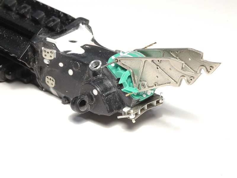 Then I could also take care of the rear dampers, sitting on top of the gear box. I had made all the parts for them along with the front damper. They are of similar construction but differ in details. Here is the parts spread for one damper. 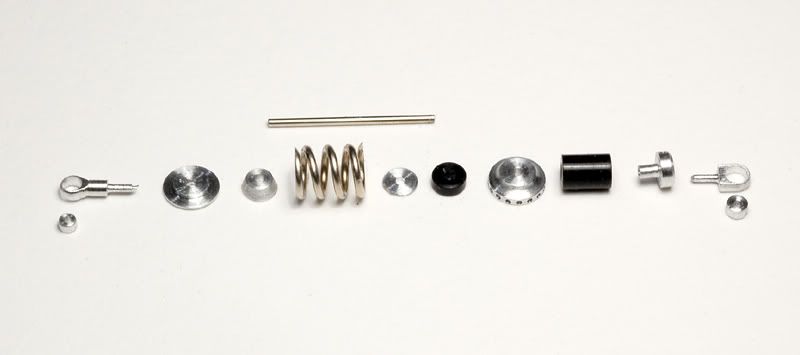 I also made new pressure reservoirs for the dampers, that sit left and right of the gearbox and will be connected to the dampers with braided line later on. The black parts are made from the kit parts ( that I forgot to take a picture of ) and the rest is turned aluminium. 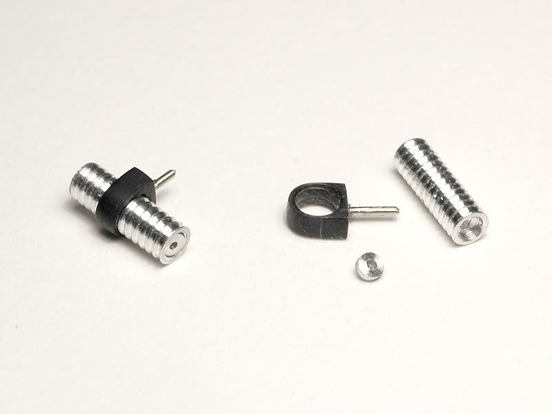 So here finally are some pictures of all the new parts dry mounted. It takes ages until everything is where it should be without glue but that was necessary to find out the correct lengths before painting. The dampers for example needed some shortening to fit and that would have been a mess after painting. 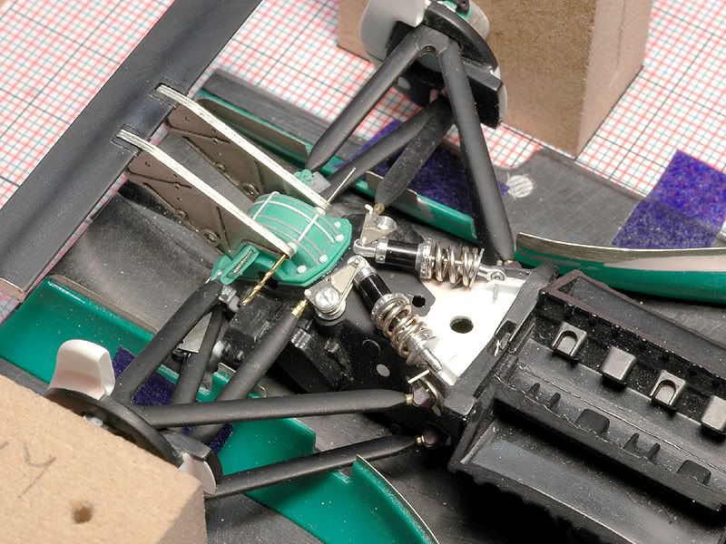 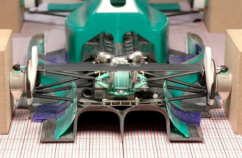 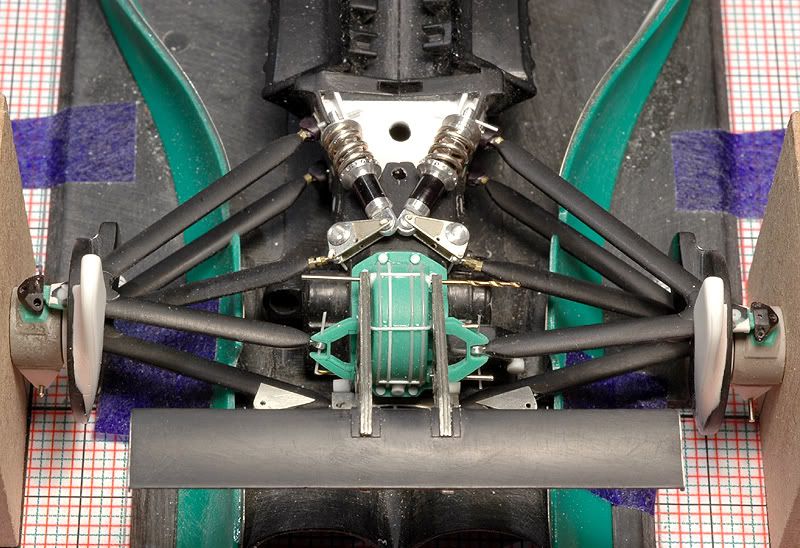 One thing I still have to do is the anti-roll-bar that is mounted to the wing supports and connected to the bell cranks ( a.k.a. damper pivots ) via thin arms. I will build that later though when the parts I have built so far are painted and assembled because Ive come to the point where I just have too many parts for dry mounting any more. One more thing I made is the gear box oil cooler that sits between the wing supports. This is a late season addition that is missing in the kit but has to be on the Spa car. From the pictures I have I figured out it should look like this: 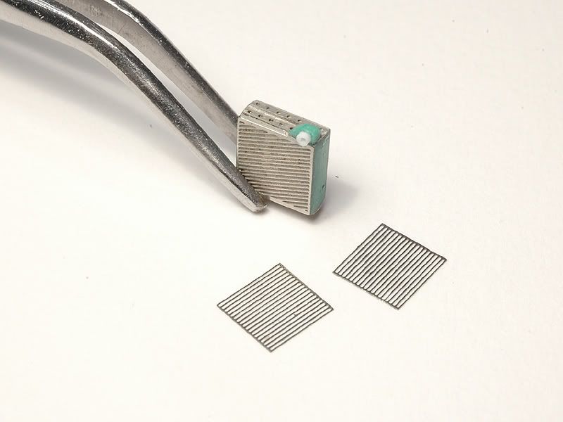 Its made from etched parts and Renshape and ready for some colour. I just hope I wont mess up those tiny meshes with paint. Thats it again. The next update may even feature some priming and painting Ill see :-) |
|
|
|
|
|
10-18-2009, 02:42 AM
|
#75 | |
|
AF Enthusiast

Join Date: Feb 2006
Location: Salonica
Posts: 1,336
Thanks: 138
Thanked 111 Times in 106 Posts
|
Re: Jordan 191
I don't believe in my eyes!!
Congratulations... |
|
|
|
|
|
 |
POST REPLY TO THIS THREAD |
 |
|
|


